
Redeth's 1989 4Runner Resurrection
 May 7, 2013 | 06:22 PM
#1441
Thread Starter
Registered User
Joined: Apr 2012
Posts: 2,817
Likes: 2
From: Los Angeles CA
All Pro Leaf Springs
Hey guys! News just keeps getting better and better..... shhhh please don't jinks me. Things have been going way too good for something to go bad. lol
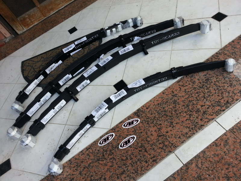
My All Pro Off-road order finally came in today. Took long enough but i finally got it. Apparently All Pro was having some issues with their fabricator or whatever company makes the springs and that is what delayed my shipping.
Front & Rear 4" Lift leaf springs.
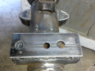
One thing i got in the package that i didnt understand was this:

My Receipt states that this piece is a "Spring Pad(Driver's Side)"
Do Any of you know why this piece was included or what for? I know it fits on the bottom side of the leaf spring(the circle piece) but i don't understand why i would only have one.
I dunno. I can just call All-Pro tomorrow and find out for myself but i guess i'm just impatient lol
So that's the update for today guys. We might get to installing the leaf springs this weekend on Saturday. and possibly even getting the sliders installed too. I'm just happy because the truck is finally going to be at the correct height it should have been from the very beginning. And happy that i'll finally be able to use the other pair of 12" travel Walker Evan's shocks!
  The Rig felt smooth as it sat already so i can only imagine how much better its gonna ride once i remove the cheapie RANCHO shocks and get those in.
My All Pro Off-road order finally came in today. Took long enough but i finally got it. Apparently All Pro was having some issues with their fabricator or whatever company makes the springs and that is what delayed my shipping.
Front & Rear 4" Lift leaf springs.

One thing i got in the package that i didnt understand was this:

My Receipt states that this piece is a "Spring Pad(Driver's Side)"
Do Any of you know why this piece was included or what for? I know it fits on the bottom side of the leaf spring(the circle piece) but i don't understand why i would only have one.
I dunno. I can just call All-Pro tomorrow and find out for myself but i guess i'm just impatient lol
So that's the update for today guys. We might get to installing the leaf springs this weekend on Saturday. and possibly even getting the sliders installed too.
I'm just happy because the truck is finally going to be at the correct height it should have been from the very beginning. And happy that i'll finally be able to use the other pair of 12" travel Walker Evan's shocks! The Rig felt smooth as it sat already so i can only imagine how much better its gonna ride once i remove the cheapie RANCHO shocks and get those in.
Last edited by Redeth005; May 7, 2013 at 06:29 PM.
May 7, 2013 | 06:56 PM
#1443
Thread Starter
Registered User
Joined: Apr 2012
Posts: 2,817
Likes: 2
From: Los Angeles CA
Check out pages 69-70 on my thread. I show pictures of what i meant. I didnt have to switch anything major out; only the shocks. And that was just temporary till this order came in.
https://www.yotatech.com/forums/f199...6/index70.html
I'm just happy that my problem will now be fixed thanks to these correct leaf springs. YAY! lol
Last edited by Redeth005; May 7, 2013 at 06:57 PM.
May 7, 2013 | 09:34 PM
#1446
Congrats on getting your new springs! The part you are un sure of ( driverside spring pad) is to level out the front so you don't have that lean that is typical with the straight axel Toyotas. If you take a look at the spring perches on your front axel, the passenger side is actually about a 1/4" taller than the driverside. When I did my SAS I made my own spring pad and just welded it on top of the driverside spring perch.
Look forward to seeing more pics of your new improved lift when it's done!

Look forward to seeing more pics of your new improved lift when it's done!
Last edited by rustED; May 8, 2013 at 10:57 AM.
May 8, 2013 | 12:39 AM
#1448
You are getting all kinds of goodies in the mail. I hear you when everything is going right, that you dont want to jink it. It is nice when things do go that way for you. Will be looking forward to more pics when done.
May 8, 2013 | 09:00 AM
#1449
Registered User
Joined: Dec 2009
Posts: 2,762
Likes: 1
Like rustedyota said. That pad is for the driver side spring perch. Toyota oem springs are different left to right in the front. Aftermarket companies didnt want to make two different types of springs for left and right so the pad was invented


 May 9, 2013 | 09:37 PM
#1452
Thread Starter
Registered User
Joined: Apr 2012
Posts: 2,817
Likes: 2
From: Los Angeles CA
Thanks for the replies guys. Now that I know about the plate now I know how to Install it.
Today was a rainy day. So I worked indoors. I decided to try working on my power windows/mirrors again. I kinda gave up on it a few months ago because I couldn't get any movement out of anything with these damn wires. I always wanted to try to get it figured out but wiring isn't my strongest skill. So I abandoned the project with hopes of eventually comong back to it.
Well today was that day. I getto rigged the wires to be powered off a 12v battery for both power and ground. I hooked everything up as well as I could from memory on the last time I played with this spaghetti soup of wires. After everything was connected. I found that I had been wiring a few thibgs wrong in the previous months I worked on it. I finally got stuff wired right and I managed to get ny mirrors to work perfectly! But as far as the windows went I still couldn't get anything to work. Then I remembered I have 2 extra master relay boxes for the windows that I pulled off of junk yard trucks just in case mine was bad. And luckily for me I did that because I concluded that the original is toast. It doesn't work at all. Once I swapped the relay box I was able to move both the power windows down (only down. Not up) by using the main driver control buttons. And then the passenger side would work both up and down when I'd use the passenger button.
Once figuring the mirrors semi figuring out the window switches I moved on and tried working with a group of loose wires that I couldn't get to work correctly. Its a pair of wires. Both solid black with red dots only one has a white line through it. Both sets of those same colora run from the power windows. And one wire alone solid black red dotted runs to the relay making it 5 wires total. This Is the bunch that I can not figure out.
I know this sounds like a bunch of jibberish when reading so I made a video to better explain myself.
Video is already uploaded. It's just in the processing stage... ill upload as soon as its done.
May 9, 2013 | 10:03 PM
#1454
Thread Starter
Registered User
Joined: Apr 2012
Posts: 2,817
Likes: 2
From: Los Angeles CA
Here we go. Video uploaded 
I'm apolgizing ahead of time. The living room carpet that I'm working on isn't the best work floor to be on when you have multiple colored wires on it trying to explain stuff. It blends in a lot lol.
I'm apolgizing ahead of time. The living room carpet that I'm working on isn't the best work floor to be on when you have multiple colored wires on it trying to explain stuff. It blends in a lot lol.
Last edited by Redeth005; May 9, 2013 at 10:06 PM.
May 9, 2013 | 10:45 PM
#1455
Registered User
Joined: Jul 2012
Posts: 2,365
Likes: 4
From: Idaho
no worries try havin 2 kids 7 cats an 2 dogs 1 bird in the house talk to me about mess an terrible carpet LOL
is the control for the mirror illuminated? that could be the extra wire at the mirror switch
also looking at the schematic for the 88 the L-W wire and L-Y work the down FROM the master switch the L-R wire feeds power to the passenger switch which is working it by passes the main switch SO trace the down wires from the drivers motor it should go to the down side of the switch
the pass side the wires go to the pass switch then to the master switch the schematic doesn't show any diodes inline
May 9, 2013 | 11:52 PM
#1456

Well you managed the impossible and got me to fuss with my tempermental computer to get at the toyota books 
I can't make out the plug/object when you asked about diodes. But the are only two diodes in the system, one for each of the door "courtesy" switches. No reason for those to be connected in your "test rig" at this point, they are both on pin 9 of the control relay..
I'd start with testing the master switch to make sure it's conducting in the up position. You would/should have conductivity for..
Drivers side UP: power from pin 1 to pin 10, and ground from pin 4 to pin 5.
Passenger side UP: power from pin 1 to pin 9, and ground from pin 4 to 6.
Next is the other sides switch. I'm pretty sure this side is fine from it working up and down already. With the switch centered you should have connections on 1-2 and 3-4. In the up position you get power from pin 5 to 1, and down you get 5 to 4.
For the questionable wires *shrug* need to know where they start at. white black is almost always direct to ground.
Some if not all of these switches are illuminated. "Power window lock s/w" ties into the "Rear power window s/w", these are G-L and R-B on the "H1" harness plug, and a blue 4 pin plug somewhere between the harness and master switch pin 1 power pin 3 ground thru the dimmer control(rheostat).
....
Essentially since it rolls down it's hooked up right. Which just leaves a broken or dirty master switch. Which unless something broke likely just needs cleaned if you can get it apart
May 10, 2013 | 12:05 AM
#1457
EDIT/PS:
You mentioned you ran direct power from the battery to the master switch in the video around 5:44. This is wired wrong.
Power is supplied from the control relay on pin 12, this splices to the master switch pin 1 and the passenger switch pin 5.
You might need to alter the wireing you have hooked up on the control relay to get the power out on pin 12(L-R) you need power input to pin 8(B-Y, IGN fuse) and ground on pin 10(W-B), also power input to pin 5(W-R, Power wnd CB). This energizes the relay and flows power from pin 5 to pin 12.
Sounds like you've essentially by-passed the relay, which isn't really a problem as long as you get the power to the switchs from the circuit breaker..
The purpose of the control relay is to allow you to roll up the windows after the ignition has been switched off for one minute or untill you open a door.
Also small note the pin numbers in the above schematic are listed as the "Turbo SR5" ones in the EWD I've linked before which is of course a handy book for identifing plugs and pinouts. Link is in Dakota's thread or someone else might have the link, pretty sure it's in chef's also.
May 10, 2013 | 06:11 AM
#1458
Registered User
iTrader: (4)
Joined: May 2010
Posts: 720
Likes: 16
From: People's Republic of California
Thank God you came back to those window switches! I thought you abandoned the project, and after all that time and work getting the system out in the RAIN, would've been a complete waste of time.
Glad you almost got it working at this point....the finish line is just a few more steps away.
Glad you almost got it working at this point....the finish line is just a few more steps away.
May 10, 2013 | 08:53 AM
#1459
Richard, just put the doohickey together with the thingy and the thing a ma Bob and that should do the trick! I hope this was helpful... Hahahahaha... just kidding, I just thought I would bring some levity really quick as I know that this wiring realm can cause some of our eyes to pop out of our head! Lol ... Really excited for you man!
May 10, 2013 | 10:37 AM
#1460
Thread Starter
Registered User
Joined: Apr 2012
Posts: 2,817
Likes: 2
From: Los Angeles CA
no worries try havin 2 kids 7 cats an 2 dogs 1 bird in the house talk to me about mess an terrible carpet LOL
is the control for the mirror illuminated? that could be the extra wire at the mirror switch
also looking at the schematic for the 88 the L-W wire and L-Y work the down FROM the master switch the L-R wire feeds power to the passenger switch which is working it by passes the main switch SO trace the down wires from the drivers motor it should go to the down side of the switch
the pass side the wires go to the pass switch then to the master switch the schematic doesn't show any diodes inline
Thanks for the schematic. Looks like the one I've got in rhe haynes manual and the one that RadRunner gave me from his FSM. I gotta re familiarize myself with the color code of the wires again. I pretty nuch have planned to do what you said. That's how I got my mirrors to work in the first place amd also the down switch. I'm gonna need to reopen my main driver side control buttons. To see if I missed something in the cleaning process last tome I worked on it.
Well you managed the impossible and got me to fuss with my tempermental computer to get at the toyota books
I can't make out the plug/object when you asked about diodes. But the are only two diodes in the system, one for each of the door "courtesy" switches. No reason for those to be connected in your "test rig" at this point, they are both on pin 9 of the control relay..
I'd start with testing the master switch to make sure it's conducting in the up position. You would/should have conductivity for..
Drivers side UP: power from pin 1 to pin 10, and ground from pin 4 to pin 5.
Passenger side UP: power from pin 1 to pin 9, and ground from pin 4 to 6.
Next is the other sides switch. I'm pretty sure this side is fine from it working up and down already. With the switch centered you should have connections on 1-2 and 3-4. In the up position you get power from pin 5 to 1, and down you get 5 to 4.
For the questionable wires *shrug* need to know where they start at. white black is almost always direct to ground.
Some if not all of these switches are illuminated. "Power window lock s/w" ties into the "Rear power window s/w", these are G-L and R-B on the "H1" harness plug, and a blue 4 pin plug somewhere between the harness and master switch pin 1 power pin 3 ground thru the dimmer control(rheostat).
Essentially since it rolls down it's hooked up right. Which just leaves a broken or dirty master switch. Which unless something broke likely just needs cleaned if you can get it apart
I'm gonna try to check that master control switch some time today. I think thevlast time I checked something wasn't making the right contactm gonna have to pull out the multimeter again lol
EDIT/PS:
You mentioned you ran direct power from the battery to the master switch in the video around 5:44. This is wired wrong.
Power is supplied from the control relay on pin 12, this splices to the master switch pin 1 and the passenger switch pin 5.
You might need to alter the wiring you have hooked up on the control relay to get the power out on pin 12(L-R) you need power input to pin 8(B-Y, IGN fuse) and ground on pin 10(W-B), also power input to pin 5(W-R, Power wnd CB). This energizes the relay and flows power from pin 5 to pin 12.
Sounds like you've essentially by-passed the relay, which isn't really a problem as long as you get the power to the switchs from the circuit breaker..
The purpose of the control relay is to allow you to roll up the windows after the ignition has been switched off for one minute or untill you open a door.
Also small note the pin numbers in the above schematic are listed as the "Turbo SR5" ones in the EWD I've linked before which is of course a handy book for identifing plugs and pinouts. Link is in Dakota's thread or someone else might have the link, pretty sure it's in chef's also.
As for the schematic I have the one that Ray gave me on the computer.
Thank God you came back to those window switches! I thought you abandoned the project, and after all that time and work getting the system out in the RAIN, would've been a complete waste of time.
Glad you almost got it working at this point....the finish line is just a few more steps away.
Glad you almost got it working at this point....the finish line is just a few more steps away.
Richard, just put the doohickey together with the thingy and the thing a ma Bob and that should do the trick! I hope this was helpful... Hahahahaha... just kidding, I just thought I would bring some levity really quick as I know that this wiring realm can cause some of our eyes to pop out of our head! Lol ... Really excited for you man!


