
RAD4Runner's 1986 4Runner dlx Build-up
 Dec 11, 2015 | 10:51 AM
#621
Registered User

Joined: Jan 2010
Posts: 3,795
Likes: 33
From: Bloodymore
Just a suggestion.
While it is easy to change the pads on IFS and SFA(virtually same setup), I would advise scouring the rotor to administer proper bedding of the new brake pad. The rotor has formed grooves identical to the previous pad as the brakes wore, and notice how shiny the rotors are now. The polished surface of the rotor will not allow the brake pad to mate properly, decreasing brake efficiency and possibly creating more heat from more pedal pressure to slow the vehicle. IF, you do not replace the rotor(notice all new rotors have cross hatching to aid in brake break-in) do you self a favor and get an orbital sander with 80-100grit and score the rotor surface(evenly) so your new pads will have more mating surface after a few good hard stops. However, you will need to score both sides of the rotor, and the dust shield makes access a bit tricky.
Toyota uses a trapped rotor design common on trucks, where one has to remove the hub to replace the rotor. This was changed in 95/96 with the introduction of the Tacoma. I have replaced my front brake setup with larger 3rd Gen 4Runner calipers and rotors when is did the SAS. This makes servicing brakes way easier. To be honest, I replace my rotors with every brake pad change, they are cheap enough, and save time from having the rotors turned. FYI, new cars use thinner rotors and are considered a one-time-use part, meaning...replace every pad change.
Dec 11, 2015 | 11:04 AM
#622
Thread Starter
Registered User


Joined: Mar 2012
Posts: 7,121
Likes: 680
Dec 11, 2015 | 11:57 AM
#623
Have you pulled the cold start injector timig switch out and cleaned it? I dont know if you tested it on the truck or not. I have had hard cold starts and it passed the test. Once I got it out, it had a hard water build up of crust on it which would not let it read the temperture properly.
Check your timing, valve adjustments, make sure all hoses are not leaking. Those are some biggies for hard starts. If it wont start easily on warm/hot days I would suspect fuel filter.
Congrats on the pad swap. Solid axles are the same way. With a micrometer and just knowing the condition of my rotors, I dont always have mine turned. Anytime I have the wheel off I give it a good look over and if everything is good just drop in new pads.
I was going to have my rotors turned and it was $20 each to have them turned. For $25 each I got new rotors. They have really come down in price. Used to not be that way. Flywheels were expensive but now they are cheap. $25 to have one turned or $55 for a brand new one. Several things it is better to replace them have machined. I am starting to check on that when I do have to change parts.
Dec 17, 2015 | 08:40 AM
#624
Thread Starter
Registered User
Joined: Mar 2012
Posts: 7,121
Likes: 680
Thanks for the tip, guys!
Yes, Terry, I cleaned and tested CSI timer switch. It's so random but more frequent now. Will check hoses, too.
You mentioned that you had propped MAF flapper at one time while starting. How much should I open it by?
Yes, Terry, I cleaned and tested CSI timer switch. It's so random but more frequent now. Will check hoses, too.
You mentioned that you had propped MAF flapper at one time while starting. How much should I open it by?
Dec 17, 2015 | 08:41 AM
#625
Thread Starter
Registered User
Joined: Mar 2012
Posts: 7,121
Likes: 680
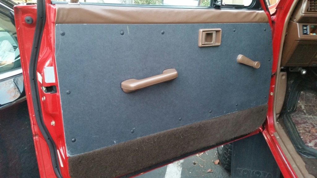
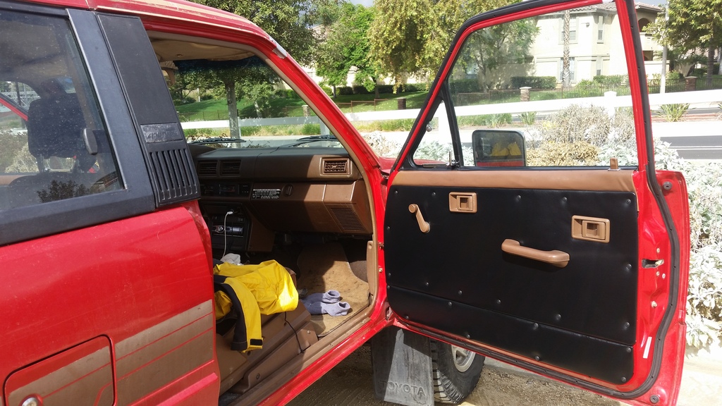
Door Panel Mod
Hi guys,
I detest hidden fasteners, dust-trapping velour and I want utilitarian, easily-removable door/body panels so here goes...
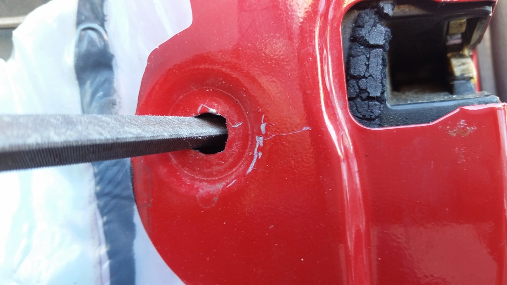
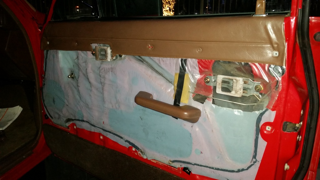
Replacing stock hidden fasteners:
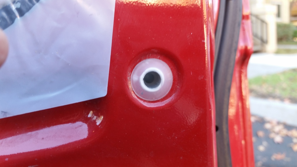
Filed corners into hole to fit the expansion/nylon nut, and keep it from rotating
Nylon nut attached:
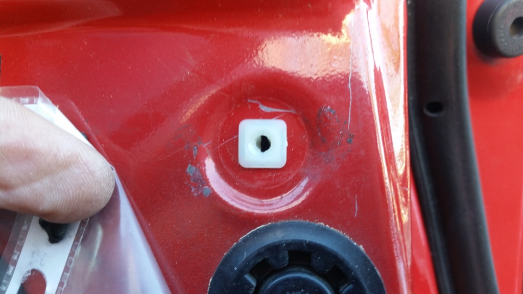
I purchased nylon nuts for 7mmx7mm hole and #8 finishing screws from www.clipsandfasteners.com.
I replaced worn out foam in window sill cover cushion with 1/8-inch thick Ensolite:
I removed worn out foam and padded with 1/8-inch Ensolite, and wrapped that with utilitarian, wipe-down black vinyl (used black vinyl because the interior is already a mix of black and brown.
I got remnant of UV-resistant vinyl for $9.00 per yard at UFO Fabrics.
I used 3M Topliner spray adhesive to hold Ensolite on board. And the edges of the vinyl wrap on the backside of the board. I did not make vinyl wrap stick on the Ensoite.
Driver's side panel was replaced with foam-core poster board just because I had some lying around.
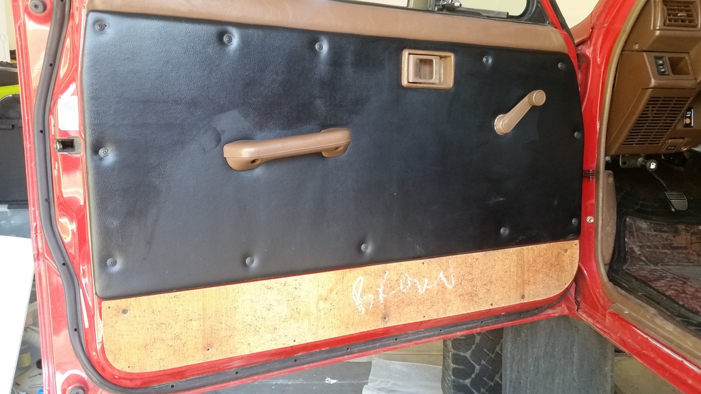
Top door panel and integrated window sill cover looked factory, but notice "Brown" noted under the carpet wrap of the bottom panel. Could it be possible that these things were customized here in the US, or they used English markings in Japan factory?
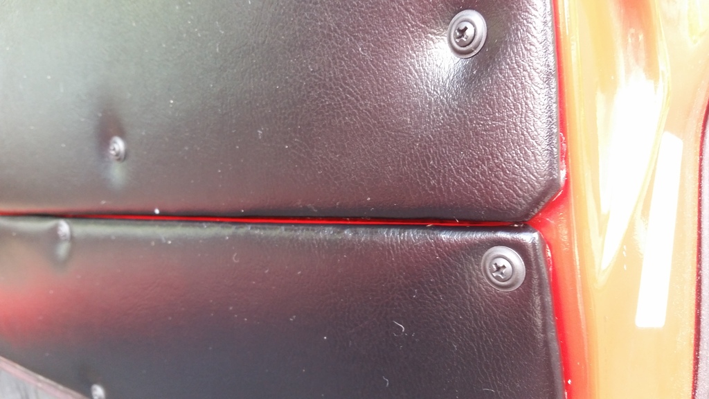
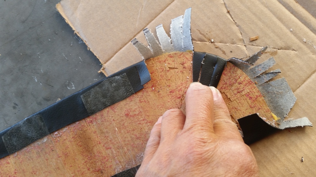
Biggest challenge I think is getting a clean wrap around sharp corners.
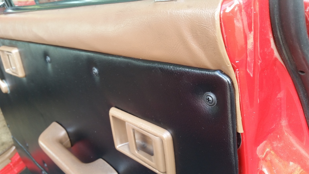
Rounded Corners aren't too bad:
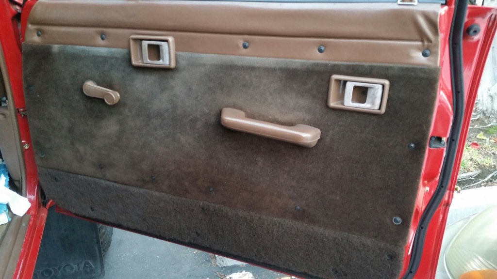
BEFORE: Dated, dust-collecting velour/carpet material on door panel and door panel attached to window sill cover, making it a PITA to work on.
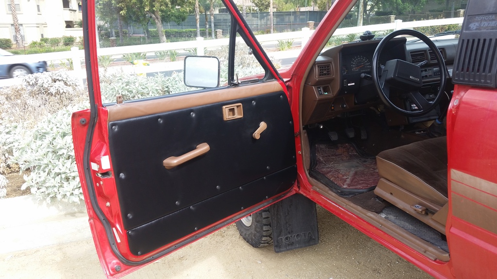
AFTER: Utilitarian black vinyl-clad door panel with simple screw fasteners. Now allows spray and wipe maintenance. Door panel and window sill cover independent of each other:
Now, because of easy access/removal/instal, I can easily add my mesh pockets in the future.
I detest hidden fasteners, dust-trapping velour and I want utilitarian, easily-removable door/body panels so here goes...
Replacing stock hidden fasteners:
Filed corners into hole to fit the expansion/nylon nut, and keep it from rotating
Nylon nut attached:
I purchased nylon nuts for 7mmx7mm hole and #8 finishing screws from www.clipsandfasteners.com.
I replaced worn out foam in window sill cover cushion with 1/8-inch thick Ensolite:
I removed worn out foam and padded with 1/8-inch Ensolite, and wrapped that with utilitarian, wipe-down black vinyl (used black vinyl because the interior is already a mix of black and brown.
I got remnant of UV-resistant vinyl for $9.00 per yard at UFO Fabrics.
I used 3M Topliner spray adhesive to hold Ensolite on board. And the edges of the vinyl wrap on the backside of the board. I did not make vinyl wrap stick on the Ensoite.
Driver's side panel was replaced with foam-core poster board just because I had some lying around.
Top door panel and integrated window sill cover looked factory, but notice "Brown" noted under the carpet wrap of the bottom panel. Could it be possible that these things were customized here in the US, or they used English markings in Japan factory?
Biggest challenge I think is getting a clean wrap around sharp corners.
Rounded Corners aren't too bad:
BEFORE: Dated, dust-collecting velour/carpet material on door panel and door panel attached to window sill cover, making it a PITA to work on.
AFTER: Utilitarian black vinyl-clad door panel with simple screw fasteners. Now allows spray and wipe maintenance. Door panel and window sill cover independent of each other:
Now, because of easy access/removal/instal, I can easily add my mesh pockets in the future.
Last edited by RAD4Runner; Jun 29, 2020 at 09:52 AM.
Dec 18, 2015 | 06:41 PM
#626
Thread Starter
Registered User
Joined: Mar 2012
Posts: 7,121
Likes: 680
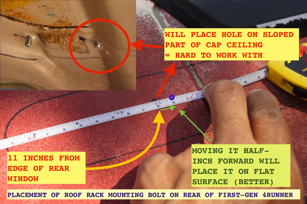
Roof Rack Mounting on First-Gen Cap
This is not a complete write-up, yet, but I want to share lessons learned ASAP - BEFORE SOMEONE STARTS DRILLING  ...will update as I have time.
Lesson Learned on Mounting Holes [so hopefully fellow members will not make same mistake] :
I find the edge of rear window to be most consistent/precise reference point.
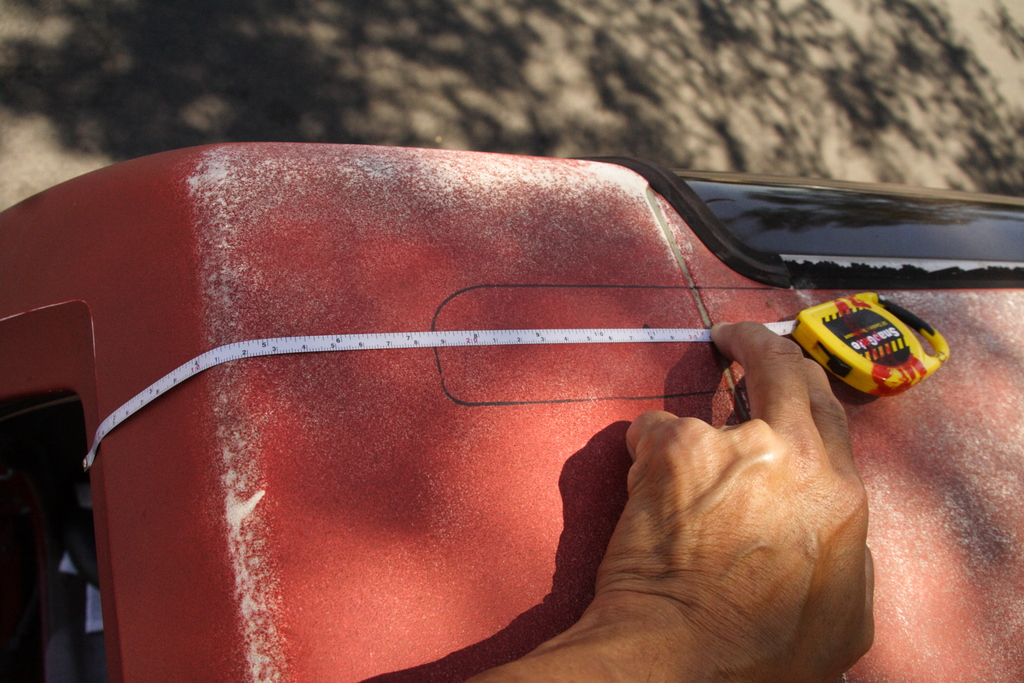
I drilled rearmost mounting hole 11 inches from that edge. This put the mounting holes for rear feet too far to the back so they ended up on a sloped section of the ceiling.
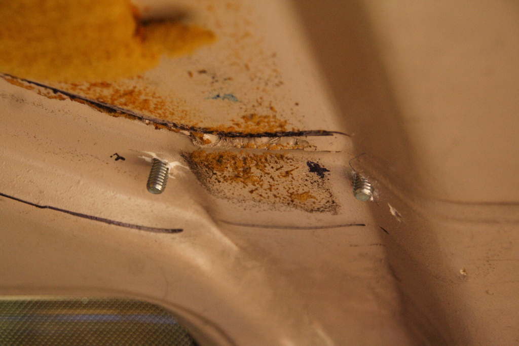
Not critical but not very clean and not as easy to work with or seal.
If you're doing this, I recommend placing the mounting hole at least 11.5 inches from that edge of the rear window. This will put the hole on flat surface of the ceiling.
I used raised-rail rack from a Blazer, trimmed to go as far back and forward as possible on the fiberglas caP, and spaced as far apart sideways to just clear the quarter window..

Note that I added center feet, to positively carry some of the weight, because load-bearing part of main feet are made of plastic and I do not trust load-bearing plastic. For the same reason, I am now using Thule cross-bars (metal resting on the raise-bars), instead of the stock cross-bars.
...will update as I have time.Lesson Learned on Mounting Holes [so hopefully fellow members will not make same mistake] :
I find the edge of rear window to be most consistent/precise reference point.
I drilled rearmost mounting hole 11 inches from that edge. This put the mounting holes for rear feet too far to the back so they ended up on a sloped section of the ceiling.
Not critical but not very clean and not as easy to work with or seal.
If you're doing this, I recommend placing the mounting hole at least 11.5 inches from that edge of the rear window. This will put the hole on flat surface of the ceiling.
I used raised-rail rack from a Blazer, trimmed to go as far back and forward as possible on the fiberglas caP, and spaced as far apart sideways to just clear the quarter window..
Note that I added center feet, to positively carry some of the weight, because load-bearing part of main feet are made of plastic and I do not trust load-bearing plastic. For the same reason, I am now using Thule cross-bars (metal resting on the raise-bars), instead of the stock cross-bars.
Last edited by RAD4Runner; Apr 23, 2017 at 07:30 AM.
Jan 1, 2016 | 10:10 PM
#627
Thread Starter
Registered User
Joined: Mar 2012
Posts: 7,121
Likes: 680
Cold-Start Injector (CSI) and Timer Circuit Errors in FSM
FOUND SOME ERRORS AND SHORTCOMINGS IN THE FSM.
First post for 2016!
While analyzing my intermittent hard-starts (long cranks) issue, I came across an article (HERE) that mentioned shortcomings of procedures for checking/inspecting Cold Start Injector timer Switch covered in the FSM.
So I verified both 1986 (print) and 1988 (pdf) FSM's and found errors and shortcomings ...
The good: Both 1986 (print) and 1988 (pdf) schematics are correct.
The Mistakes:
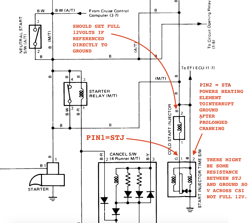
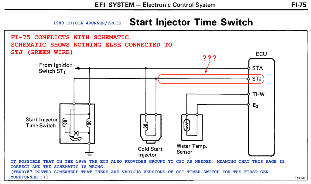
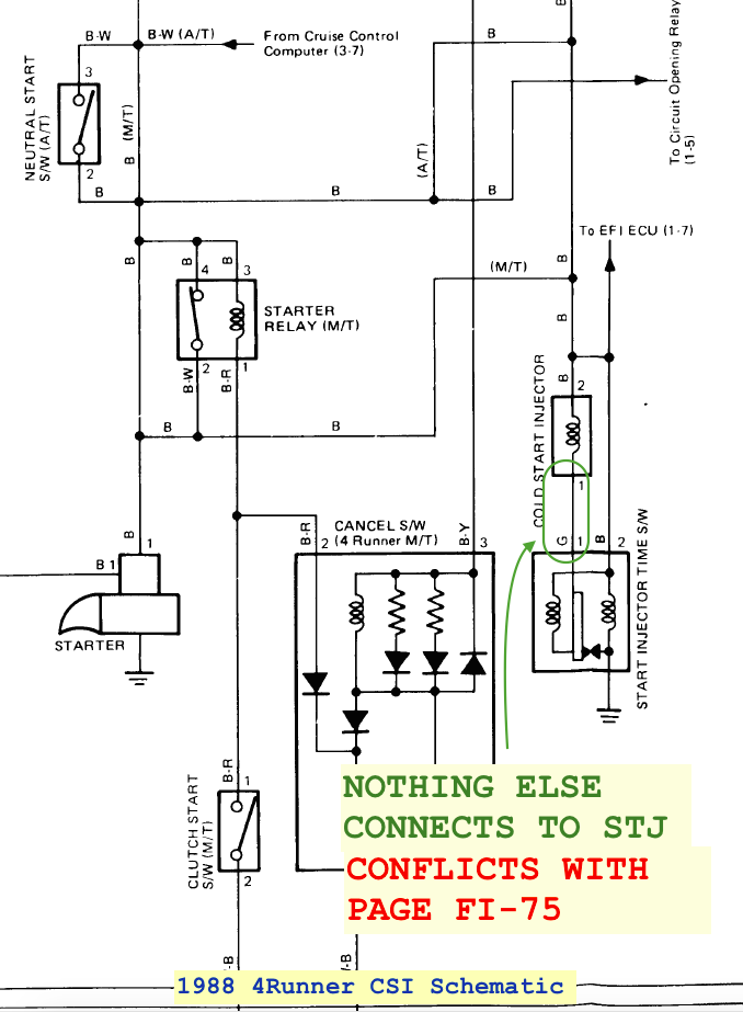
1988 (pdf) FSM section for checking the CSI timer (page FI-75) shows a wrong circuit, and says that STA and positive side of CSI take power from IG Switch. No they do not. They take power from starter relay (if manual), or neutral safety switch (if auto). Corrected circuit is here:
[NEED TO UPDATE SCHEMATIC]
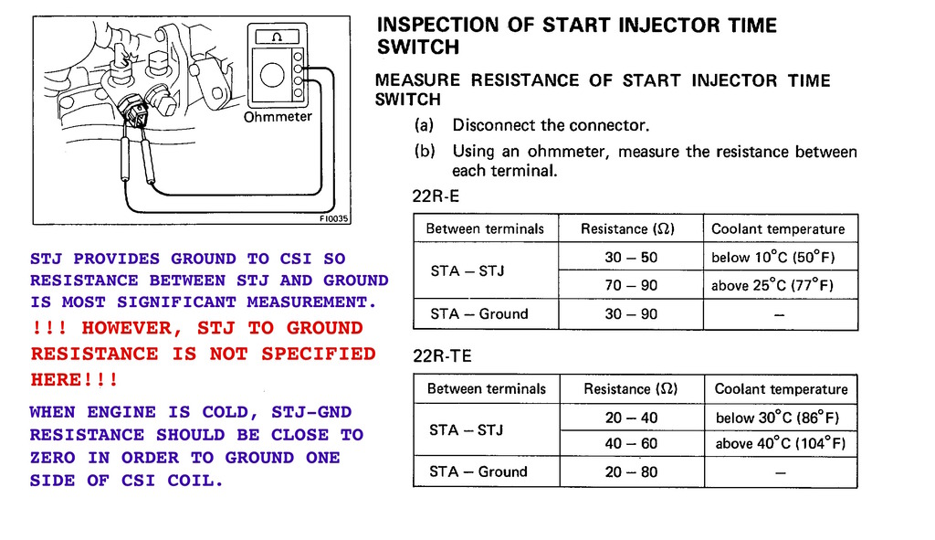
Both the 1986 and 1988 checks section fail to specify STJ to ground resistance. While one side of the CSI takes full12V, the STJ pin of CSI timer switch provides ground. Therefore, like the article mentioned above says, resistance between STJ and ground (brass body of the CSI timer switch) should be the significant measurement. It should be close to zero ohms when engine is cold. (I will measure mine next time I get the chance).
Because STJ amy have some resistance to ground, it is possible that measuring voltage at the CSI connector may not yield a full 12Volts. (Again I'll measure mine when I get the chance).
[NEED TO UPDATE SCHEMATIC]
Both the 1986 and 1988 checks section fail to specify STJ to ground resistance. While one side of the CSI takes full12V, the STJ pin of CSI timer switch provides ground. Therefore, like the article mentioned above says, resistance between STJ and ground (brass body of the CSI timer switch) should be the significant measurement. It should be close to zero ohms when engine is cold. (I will measure mine next time I get the chance).
Last edited by RAD4Runner; Apr 23, 2017 at 07:41 AM.
Jan 2, 2016 | 04:30 AM
#628
Nice job on the door panels.
I like the mesh pocket idea. My wife's Forester has some and they are quite handy.
I think the 94 will get some.
Looking forward to seeing the rest of the roof rack.
I like the mesh pocket idea. My wife's Forester has some and they are quite handy.
I think the 94 will get some.
Looking forward to seeing the rest of the roof rack.
Jan 4, 2016 | 11:14 AM
#629
Thread Starter
Registered User
Joined: Mar 2012
Posts: 7,121
Likes: 680
Various csi setups
In a separate thread, I wondered...
I dug deeper into it and realized that CSI circuit varies from one model-year to another.
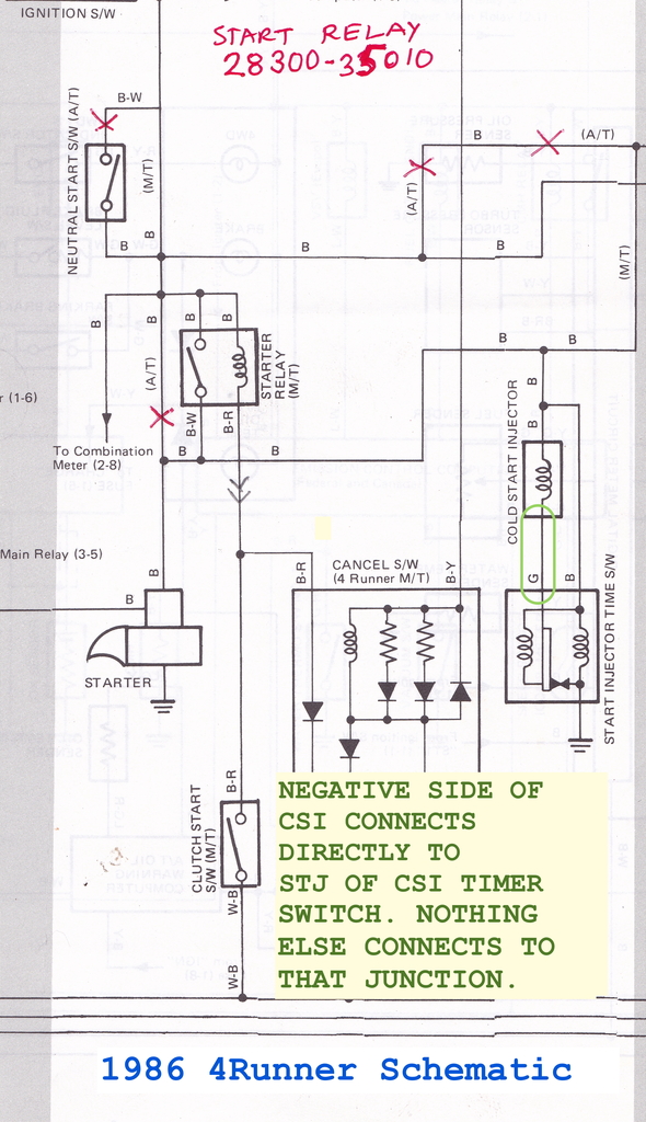
(1)In the 1986 and the 1987 (see wally's comment below) 4Runner 22R-E, the CSI Timer Switch SOLELY controls the CSI. There is no connection between the ECU and the CSI or the CSI timer switch.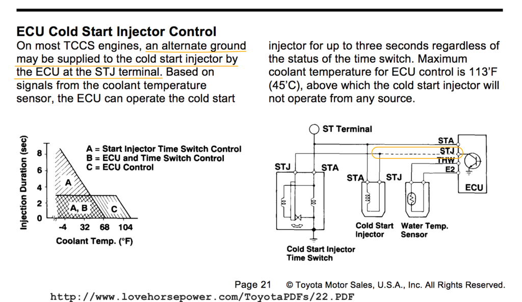
(2) Probably applies to the 1988 4Runner 22R-E (ECU connects to STJ of CSI):
(1)In the 1986 and the 1987 (see wally's comment below) 4Runner 22R-E, the CSI Timer Switch SOLELY controls the CSI. There is no connection between the ECU and the CSI or the CSI timer switch.
Schematic agrees with CSI Check/Inspection section diagram.
Scans of print schematic and CSI Time Switch Inspection:
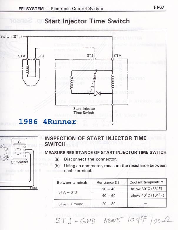
(2) On some engines, the ECU may take part in providing ground to the ECU:Scans of print schematic and CSI Time Switch Inspection:
i have an '87... the FSM shows the same schematic as the '86, and the same specific diagram for the CSI time switch, ie, no connection shown in either with the ECU for STJ. the ECU labels on the wiring diagram do not show STJ, but do show STA. have not verified in the actual wiring whether this is true, but the FSM shows the '87 to be the same as the '86.
wally
wally
CSI Timer Switch Check section on page FI-75 shows this. However, the schematic does not. (From PDF version of FSM)
So... how about the 1987? ... jstluise, scope103 and I were working on that here
Last edited by RAD4Runner; Mar 7, 2017 at 12:29 PM.
Jan 4, 2016 | 10:39 PM
#630
Thread Starter
Registered User
Joined: Mar 2012
Posts: 7,121
Likes: 680
Prepping Pinchweld for Windshield Install
Hi guys!
Windshield leaks again so I would appreciate your inputs, especially if based on your first-hand experience. Please see this thread.
Windshield leaks again so I would appreciate your inputs, especially if based on your first-hand experience. Please see this thread.
Jan 4, 2016 | 11:23 PM
#631
I have an 85 FSM and I have found several errors in it. On the AFM, I have only seen it throw an engine code only when it is disconnected. I have quite a few AFMs that were bad and never throw a code. When I get a replacement, I take a manual and my meter and run some checks on it when in the yard and make sure the flapper is operating freely.
On your question about how far I open it, I stick a screwdriver handle in the flapper to hold it open and I forget where I run the pointed end either to the distributor or some place to help hold it open. It is actually open a lot. What I am checking for in that check is to see if it starts up any quicker. If the flapper is slow to respond, it will delay the Circuit Opening Relay which energizes the fuel pump. With the flapper stuck open, and the black air tube removed, you are tricking the computer and COR into operating. You can rev the motor up and it will be running rough but it does kind of help to see if the AFM is working correctly.
On your windshield, they use a black rubbery glue then set the windshield in. Even after the windshield is in, there is still about a 1/4 inch gap around the windshield and the body. If glue has any opening at all water will find its way inside the cab. One place you may be able to find where the leak is, is to remove the A-pillar trim and see if it running down inside of it and down beside the dash.
I remove the windshields and grind all of the rust out. You will not be able to get it down to bare metal in some cases as it can get really pitted. Then I seal it with some sealant like POR to cover the rust. Even the windshield shop I use, tells me that in most cases that shops wont go the extra effort to try and get most of the rust out and just add sealant/glue over the channel.
Once the windshield was in, I had them to put a coat of sealant over the glass and to the windshield channel as usually I just see them add the sealant and then stick the glass in.
Your truck being a California truck should not have an issue but is there by chance some rot in the cowl just in front of the windshield? Remove your wiper blades, and there are three screws that hold the cowl on and a plastic clip on each end of the cowl. You will need a real stubby screw driver to get then out or a 90 degree screw driver/allen wrench type to get them out without pulling off the hood.
Remove your cowl and see if there is any rust holes in the cowl area. I have seen cowls full of debris and it can hold moisture and rust a hole in the cowl. Grind down to clean metal and you can use a fiberglass patch to seal the hole if there is one there.
Gizzlers 85 runner thread I think shows something similar to the scenario that I just mentioned where it was leaking thru the cowl.
To get your A-pillar trim off, use a thin flat blade screw driver and you will slide it in between the trim and body until you find the top and middle clips. Once you bump into the clips, you can basically twist the screw driver which will pop the clips straight out. The bottom of the trim is held on by a clip, but to get it off, just lift the trim up about 1/4, to 1/2 inch to get it out of the hole in the body. Do the top clip, then the middle clip and then lift trim.
With the trims off, run a water hose along the top, the water should run to the edges and you should be able to see if water is coming in from the sides.
Last edited by Terrys87; Jan 4, 2016 at 11:42 PM.
Jan 5, 2016 | 12:03 AM
#632
Thread Starter
Registered User
Joined: Mar 2012
Posts: 7,121
Likes: 680
Thanks and Happy New Year, Terry!
YEs, I have A-pillar trim removed. It fell part so it went into recycling bin - LOL!
It's leaking through the top seam. Dripped from driver's end of the headliner trim. Will call Safelite tomorrow. This would be the second time Safelite fixes it.
YEs, I have A-pillar trim removed. It fell part so it went into recycling bin - LOL!
It's leaking through the top seam. Dripped from driver's end of the headliner trim. Will call Safelite tomorrow. This would be the second time Safelite fixes it.
Jan 5, 2016 | 06:23 AM
#633
wally
Last edited by wallytoo; Jan 5, 2016 at 06:26 AM.
Jan 5, 2016 | 09:55 AM
#634
Thread Starter
Registered User
Joined: Mar 2012
Posts: 7,121
Likes: 680
i have an '87. i also have the FSM. the FSM shows the same schematic as the '86, and the same specific diagram for the CSI time switch, ie, no connection shown in either with the ECU [edit] for STJ. the ECU labels on the wiring diagram do not show STJ, but do show STA. have not verified in the actual wiring whether this is true, but the FSM shows the '87 to be the same as the '86.
wally
wally
It's really nice when fellow members share what they have found out about their specific trucks. Helps us troubleshoot more accurately - no guessing.
Terry,
You mentioned somewhere that there are different CSI timer switches for the first-gen 4Runner. Above post shows that CSI ckt for 1986-1987 are the same and 1988 is different (there is STJ connection to ECU). So... the CSI timer switch part changed on the 88, then?
Jan 5, 2016 | 03:03 PM
#635
Thread Starter
Registered User
Joined: Mar 2012
Posts: 7,121
Likes: 680
Control of Rear Window from inside Rear Deck
Finally, a video of rear deck control for my window while camping... Also shows the LED strip I added with same 2-way control as the stock deck light. The anemic stock light has now been relegated to night-light duty - LOL!
Jan 12, 2016 | 05:48 AM
#636
Nice I know I have a extra switch somewhere that I can use someday to do the same. And once I get settled on my body work, I would love to add a rear LED light like yours so I can see what I'm looking for at night.
 Feb 4, 2016 | 08:45 PM
#638
Thread Starter
Registered User
Joined: Mar 2012
Posts: 7,121
Likes: 680
Preparing Pinchweld for Windshield Replacement
One of my (not critical but) annoying issues right now.
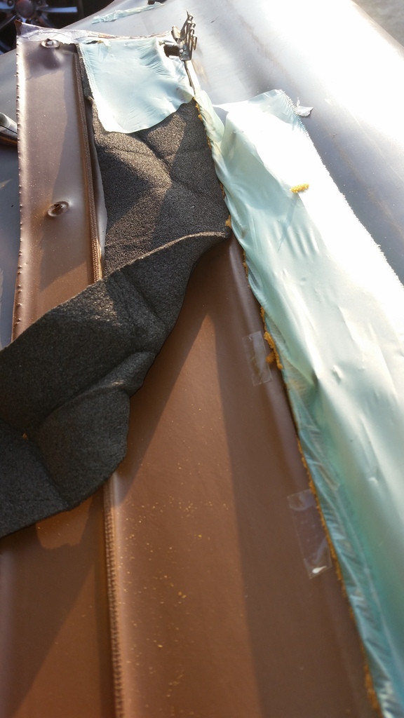
I did my best to repair the rusted sections:
(1) Stripped down to bare metal,
(2) Applied rust converter - Permatex,
(3) Primed
(4) Painted (spray can)
However, windshield still leaked during heavy rain. Safelite re-installed glass under warranty, but last week it leaked again. Same place - upper right-hand corner.
Shop will repair under warranty but that would be waste of time, money, and other resources. So I'm approaching mine more thoroughly.
Potential points of failure are:
(1) Between glass and urethane adhesive (beyond my control).
(2) Between urethane adhesive and paint,
(3) Between paint and primer,
(4) Between primer and rust-converter/protectant
(5) Between rust converter and metal.
Therefore, I want to try as less number of layers (or points of failure) as possible that would still:
(1) Protect from rust, AND
(2) Allow good adhesion.
Thoughts I have, that I hope bodywork experts in this forum can comment on, and I also wanna ask urethane windshield adhesive manufacturer (SIKA?) are:
(1) Is POR-15 rust protectant also rust a converter?
(2) Would POR-15 directly on metal be good?
(3) Is POR-15 as good as primer so I can simply paint directly on it, eliminating the primer layer?
(4) Some people online say POR-15 is compatible with the urethane adhesive. If so, then why not simply apply adhesive directly on POR-15 and mount glass, eliminating primer and paint layers?
IF anyone knows exactly the proper procedure, that will prevent rust and allow good adhesion, May we know what process you used?
Feb 5, 2016 | 08:20 AM
#639
Registered User
Joined: Jan 2010
Posts: 3,795
Likes: 33
From: Bloodymore
(1) Is POR-15 rust protectant also rust a converter?
I am not entirely sure about this, but it is suppose to neutralize the rust, as well as cover it to slow or stop its progress.
(2) Would POR-15 directly on metal be good?
This is the only way you can apply POR-15, you will also want to use their metal prep solution to pretreat the metal.
(3) Is POR-15 as good as primer so I can simply paint directly on it, eliminating the primer layer?
Paint does not like adhering to POR-15.
(4) Some people online say POR-15 is compatible with the urethane adhesive. If so, then why not simply apply adhesive directly on POR-15 and mount glass, eliminating primer and paint layers?
Urethane requires a primer to bond correctly, that primer may not be compatible with POR-15. Also, POR-15 does not bond to bare metal the way a metal etch primer does, therefore, windshield failure could be an issue.
With all that said, I have a leak also. I thought it was my windshield, so I took a garden hose and ran water around the seal and no leak. Then I took duct tape and taped the windshield gasket and tried the test on the sunroof, and viola sun roof leaks, I think one of my drain hoses has come loose and the water runs down like the top of my windshield is leaking.


