
1987 4Runner Cyber Dude
 Apr 27, 2014 | 12:19 PM
#521
Thread Starter
Registered User
iTrader: (1)
Joined: May 2012
Posts: 835
Likes: 2
From: South Florida
Sorry, don't remember. It's just a random item I bought at an electronics market place in China  - 5 stories of various electronics, tools, appliances, gadgets, even a bbq chicken stand nex to an electronics booth - LOL!
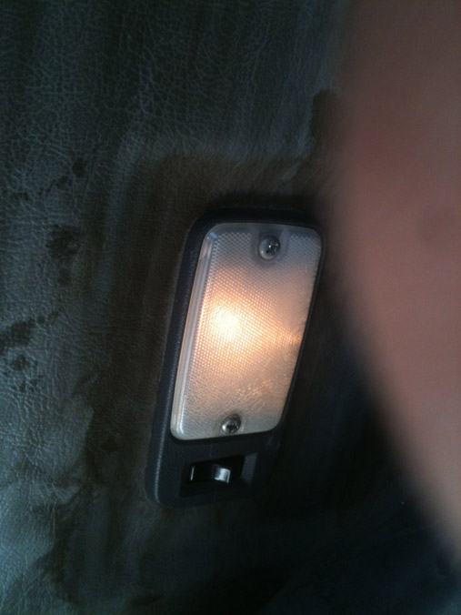
Pretty much any 12V LED strip would do. Just test it at the store.
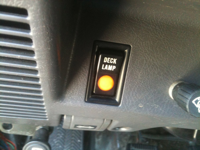
I used used a single-pole double-throw switch (used a power antenna up-down switch) to do same as stock deck light switch, Then I wired existing deck switch to be just a plain on-off light as a night light. Will put red LED bulb in there.
Regards,
RAD
- 5 stories of various electronics, tools, appliances, gadgets, even a bbq chicken stand nex to an electronics booth - LOL!Pretty much any 12V LED strip would do. Just test it at the store.
I used used a single-pole double-throw switch (used a power antenna up-down switch) to do same as stock deck light switch, Then I wired existing deck switch to be just a plain on-off light as a night light. Will put red LED bulb in there.
Regards,
RAD
 Apr 27, 2014 | 12:49 PM
#522
Thread Starter
Registered User
iTrader: (1)
Joined: May 2012
Posts: 835
Likes: 2
From: South Florida
I played around with the door buzzer a little today. I found a clear connection all the way from the door switch to the door buzzer. from there I don't have a connection to the dome light. I checked all the wires coming from the buzzer to the connecter leading up to the dome, noting. I checked the passenger door to the same connector leading up to the dome and I get continuity. I'm not sure, but from the connector at the buzzer to the connector to the dome I may have a short. The only way I can see myself tracing that is taking apart the dash which may happen when i change the bulbs when i receive them.

Going over to the buzzer, there doesn't look to be anything working with it. the actual door, seat belt, and ignition buzzer work fine. the Black/Red wire seems to be the wire in question. I tried tracing it but like I said it runs up under the dash. As for the buzzer, i wish I had the schematics for it it would help me a little I know very little about electronics.
Well, The light will remain the same until I can figure out more.
I did fiddle with the bad brake booster and think it could be fixed. I will purchase the retainer and seal from toyota to see if it will keep a vacuum.
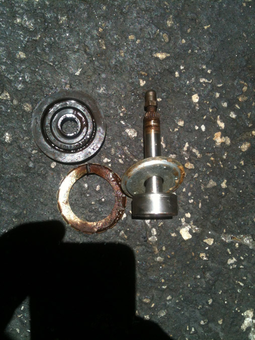
Here's a picture of the rod I popped out of the booster retainer and seal.

Looking inside it looks pretty new.
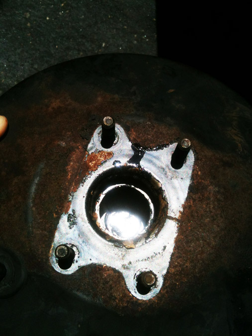
I am going to purchase the retainer and seal shown here.
Going over to the buzzer, there doesn't look to be anything working with it. the actual door, seat belt, and ignition buzzer work fine. the Black/Red wire seems to be the wire in question. I tried tracing it but like I said it runs up under the dash. As for the buzzer, i wish I had the schematics for it it would help me a little I know very little about electronics.
Well, The light will remain the same until I can figure out more.
I did fiddle with the bad brake booster and think it could be fixed. I will purchase the retainer and seal from toyota to see if it will keep a vacuum.
Here's a picture of the rod I popped out of the booster retainer and seal.
Looking inside it looks pretty new.
I am going to purchase the retainer and seal shown here.
Apr 27, 2014 | 10:09 PM
#523
Never thought of rebuilding the booster. Looking to see how it works for you. The dome light plug is up in the very far top left hand corner of the firewall. I am not sure how it is eventually connected to the buzzer. Seems to me it a blue plug. It is sort of just above the fuse box and forward to the firewall.
Apr 28, 2014 | 05:14 AM
#524

Cant help you on the door buzzer as I have yet to tear into that.
I am interested to see how the brake booster goes as well. I like finding out ways to revive the OEM parts as much as I can. I really hate buying the aftermarket crap from the parts stores. I have a few OEM starters, and alternators that need rebuilding, maybe ill look into doing a booster as well.
I am interested to see how the brake booster goes as well. I like finding out ways to revive the OEM parts as much as I can. I really hate buying the aftermarket crap from the parts stores. I have a few OEM starters, and alternators that need rebuilding, maybe ill look into doing a booster as well.
Apr 28, 2014 | 09:23 AM
#525
Thread Starter
Registered User
iTrader: (1)
Joined: May 2012
Posts: 835
Likes: 2
From: South Florida
Never thought of rebuilding the booster. Looking to see how it works for you. The dome light plug is up in the very far top left hand corner of the firewall. I am not sure how it is eventually connected to the buzzer. Seems to me it a blue plug. It is sort of just above the fuse box and forward to the firewall.
The Dome light has been a challenge. I can't tell you what color I'm looking only what i can see, as I get older my seeing gets worse or is it I start seeing things. I played with the plug from dome from the get go as I traced it with my toners to there. From that plug there is power Black/White wire and Black/red (maybe blue) shows continuity from the passenger switch, but doesn't show continuity from the drivers switch. Checking continuity from the drivers side switch to the buzzer it is good. Looking at the buzzer (wish I had the schematics for the buzzer). Checking the wires on the buzzer plug, i figured out that the red/white wire in the buzzer plug leads to the passenger switch and the dome light [plug at the side kick panel. The The red wire in the buzzer plug leads to the drivers side door switch and has continuity to it. No cut, breaks or shorts in the wires so far. Thus nothing to check further with the wires. Here's a rough sketch of what I mean when I say I have continuity. THE BLUE LINE IS JUST SHOWING YOU WHERE i HAVE CONTINUITY. The rest are the wires and the buzzer box and dome light.
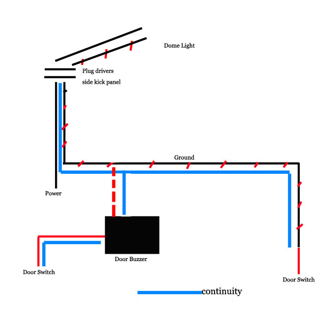
If i'm getting continuity from the line leading in to buzzer from the door switch and continuity leading from the buzzer to the dome light plug, then that leads me to believe there is something wrong with the buzzer.
Checking on the buzzer, here's what it looks like.
#2 in the picture below is the in coming from drivers Door switch. (red Wire)
#1 is the out going going to the dome light. (red/White wire)
#3 is what is called a signal diode. Not sure of this as my knowledge of electronics is very small, but someone here may know better.
If it is a signal diode I can assume it is bad. A signal diode should get a reading when reading on one side of the diode. This diode should be a one way current this is why I assume its a signal diode. #1 in connector in the picture is also singled out on the board and the only connections are from the red wire #2 through the diode #3 and then out to the dome light #1.
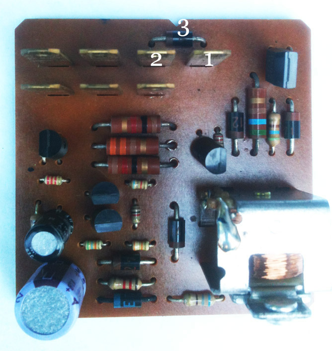
With that in mind that leads me to believe the diode maybe bad. I tried checking continuity on the diode by testing continuity from both sides of the diode pole. Those came up with 0 either way. Nothing passing through.
Last edited by junk4u; Apr 28, 2014 at 09:31 AM.
 Apr 28, 2014 | 01:24 PM
#528
Rad4runner is great at stuff like this. I would ask him for advice. I am not sure if that is a diode or not. I know in a diagram it is a little triangle symbol but that is about it.
Apr 28, 2014 | 09:50 PM
#529
Thread Starter
Registered User
iTrader: (1)
Joined: May 2012
Posts: 835
Likes: 2
From: South Florida
Thanks Terry I'm going to do that here and now.
Okay RAD4Runner, got the question for you do you have any idea what #3 is in that picture above of the circuit for the buzzer? I am assuming its a diode of some sort. I get no readings from it going either way which I'm going to assume it's dead. If you know anything or possibly which one it is can you let me in on that secret?
I want to see if I can just change it out de-solder and re-solder a new one
Apr 29, 2014 | 01:04 AM
#530
Registered User


Joined: Mar 2012
Posts: 7,125
Likes: 681
Thanks Terry I'm going to do that here and now.
Okay RAD4Runner, got the question for you do you have any idea what #3 is in that picture above of the circuit for the buzzer? I am assuming its a diode of some sort. I get no readings from it going either way which I'm going to assume it's dead. If you know anything or possibly which one it is can you let me in on that secret?
I want to see if I can just change it out de-solder and re-solder a new one
Okay RAD4Runner, got the question for you do you have any idea what #3 is in that picture above of the circuit for the buzzer? I am assuming its a diode of some sort. I get no readings from it going either way which I'm going to assume it's dead. If you know anything or possibly which one it is can you let me in on that secret?
I want to see if I can just change it out de-solder and re-solder a new one
Junk4u,
Yes, that's a Diode. If it's connected to dome switch circuit, go ahead and test it.
Disconnect all you can from the module.
White stripe is Cathode (negative side).
If something's connected to it on the board, need to use resistance measurement.
Set to ohms, black probe on cathode (stripe end), red on other end: You should get zero ohm (or less than 1 ohm)
Reverse probes. You should get high resistance, depending on what's connected to it.
BTW, do you have dlx or SR5?
Apr 29, 2014 | 04:44 AM
#531
Thread Starter
Registered User
iTrader: (1)
Joined: May 2012
Posts: 835
Likes: 2
From: South Florida
Tnx, Terry
Junk4u,
Yes, that's a Diode. If it's connected to dome switch circuit, go ahead and test it.
Disconnect all you can from the module.
White stripe is Cathode (negative side).
If something's connected to it on the board, need to use resistance measurement.
Set to ohms, black probe on cathode (stripe end), red on other end: You should get zero ohm (or less than 1 ohm)
Reverse probes. You should get high resistance, depending on what's connected to it.
BTW, do you have dlx or SR5?
#1 is not connected to anything else on the board just the diode leading to in coming #2 from door switch (diode bridge marked in red). On the back side of the board image shown below you can see it better.
#2 coming from the door switch is connected to the board which you can see leads to other parts of the board I marked the bridge in green.
I'm thinking this diode has gone bad and the bridge that should be across from #2 to #1 is severed which means the dome light would not work.
This only logic and could be incorrect, but I can't see any other short any where everything else leading from the door switch to this buzzer #2 has continuity and from Buzzer #1 leading to dome light has continuity.
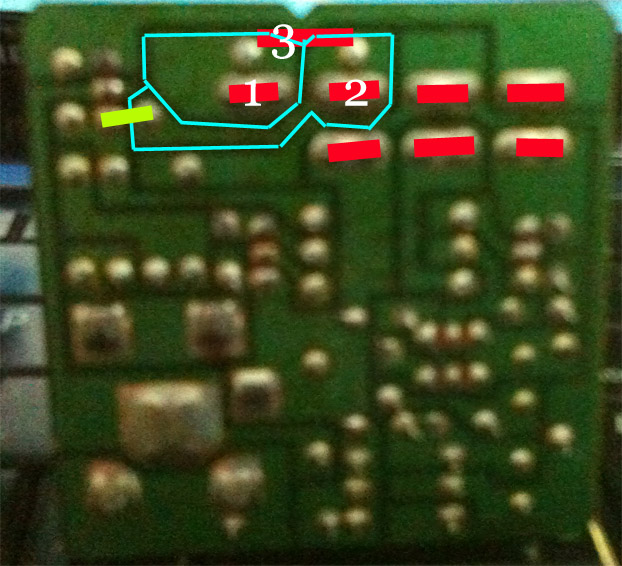
What is the easiest way to determine which diode this is as can't reading anything on it only the dark brown with light brown stripe.
I wish it were easier for me to get parts for this truck, but down here in South Florida that is proving to be difficult.
May 1, 2014 | 05:02 AM
#532
Thread Starter
Registered User
iTrader: (1)
Joined: May 2012
Posts: 835
Likes: 2
From: South Florida
I'm guessing no one has the answer to what diode #3 this is in the image that was attached.
Terry if you have an extra buzzer lying around, could you see if you can get the numbers off it, I can only read what looks like 271 on the one I have.
Terry if you have an extra buzzer lying around, could you see if you can get the numbers off it, I can only read what looks like 271 on the one I have.
May 1, 2014 | 05:08 AM
#533
Would a picture work better? lol
Copied...
I thought I was going to fix a problem and created another. I always got tired of hearing my door buzzer alarm and first thing I did was find it under the Steering Column.
All was fine until I noticed that I did not have a dome light when I opened the drivers door. Passenger door worked and so did the switch on the cab. First thing I thought was the door switch was bad or dirty or corroded. I checked it out and it was good.
Did some looking around and you have to have the door alarm in for the drivers door light to work.
Also found the cure for the alarm on YT. Just bent the tab out a little so as not to make contact. If you ever want to hear it again, it can be bent back in.
Here is the Buzzer Box under the Steering Column.

Just bend the tab out from the bottom a little bit.

Here it is going back together. There are 2 tabs to the cover that I just pryed a pocket knife. Life is good now.

Apparently this is a fairly common problem. What I found on different threads is that a lot of the door switches and buzzers get removed. This was as far as I had to go to troubleshoot. Also I did find that by bending the tab you can control how loud the buzzer is.
Copied...
I thought I was going to fix a problem and created another. I always got tired of hearing my door buzzer alarm and first thing I did was find it under the Steering Column.
All was fine until I noticed that I did not have a dome light when I opened the drivers door. Passenger door worked and so did the switch on the cab. First thing I thought was the door switch was bad or dirty or corroded. I checked it out and it was good.
Did some looking around and you have to have the door alarm in for the drivers door light to work.
Also found the cure for the alarm on YT. Just bent the tab out a little so as not to make contact. If you ever want to hear it again, it can be bent back in.
Here is the Buzzer Box under the Steering Column.
Just bend the tab out from the bottom a little bit.
Here it is going back together. There are 2 tabs to the cover that I just pryed a pocket knife. Life is good now.
Apparently this is a fairly common problem. What I found on different threads is that a lot of the door switches and buzzers get removed. This was as far as I had to go to troubleshoot. Also I did find that by bending the tab you can control how loud the buzzer is.
Last edited by Terrys87; May 1, 2014 at 01:05 PM.
May 1, 2014 | 05:12 AM
#534
Thread Starter
Registered User
iTrader: (1)
Joined: May 2012
Posts: 835
Likes: 2
From: South Florida
Thanks Terry, I should have been a little more clear. The number off the Diode on the circuit board. If you look at the images I posted of my board, you can see it is #3 above the blades. I can hardly see mine could be an age thing or it could be because it goes around where I can't see it LOL...
May 1, 2014 | 05:15 AM
#535
Give me about 5 minutes. I will go pull the buzzer out of the 86 truck and disable the buzzer on it. I am waiting for it to warm up and it is driving me nuts. I can do it in the house.
I am blind as a bat for small print. Cant find Mistys glasses or my magnifying glass so will see if it will show here.
Let me try again.
I found a set of her glasses. On the diode itself it is B12. You have a stripe at the top of the diode and then below it it says B12.
I am blind as a bat for small print. Cant find Mistys glasses or my magnifying glass so will see if it will show here.
Let me try again.
I found a set of her glasses. On the diode itself it is B12. You have a stripe at the top of the diode and then below it it says B12.
Last edited by Terrys87; May 1, 2014 at 05:37 AM.
May 1, 2014 | 05:48 AM
#538
Thread Starter
Registered User
iTrader: (1)
Joined: May 2012
Posts: 835
Likes: 2
From: South Florida
Terry, no that's not what I needed. It's the number on the diode.
Here's a picture of mine, I can;t see the numbers to well on mine it's #3 on the image. Those little diodes have numbers on them which tells you what they are. That diode seems to be the bridge from the door switch to the dome light.
If you can look at the diode and see if you can see what the numbers or letters on it are that would help me tremendously.
See #3 on the image:


