When you click on links to various merchants on this site and make a purchase, this can result in this site earning a commission. Affiliate programs and affiliations include, but are not limited to, the eBay Partner Network.
Hey you guys.
New guy here, Please be patient and understanding with me please.
I bought a used 1988 4-Runner, My second one and I lover her. But she needs some love back.
Bottom line is I need the after market Wiring information for the a 1988 toyota 4-Runner part #84884-000809 Driver Side Master Power Door Switch
The driver side window never rolled down. Then the passenger side window stopped rolling down. (rear window rolls down intermittently Ill work on that another day)
Trouble shot the fuses, hot wired the windows motor.
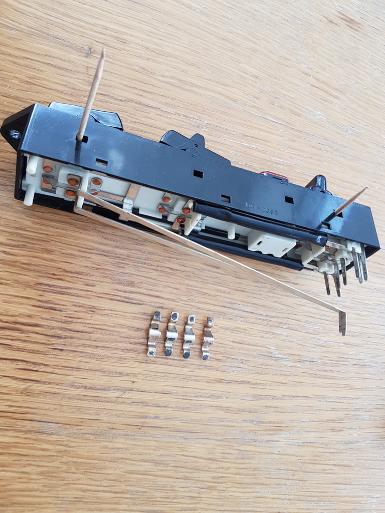
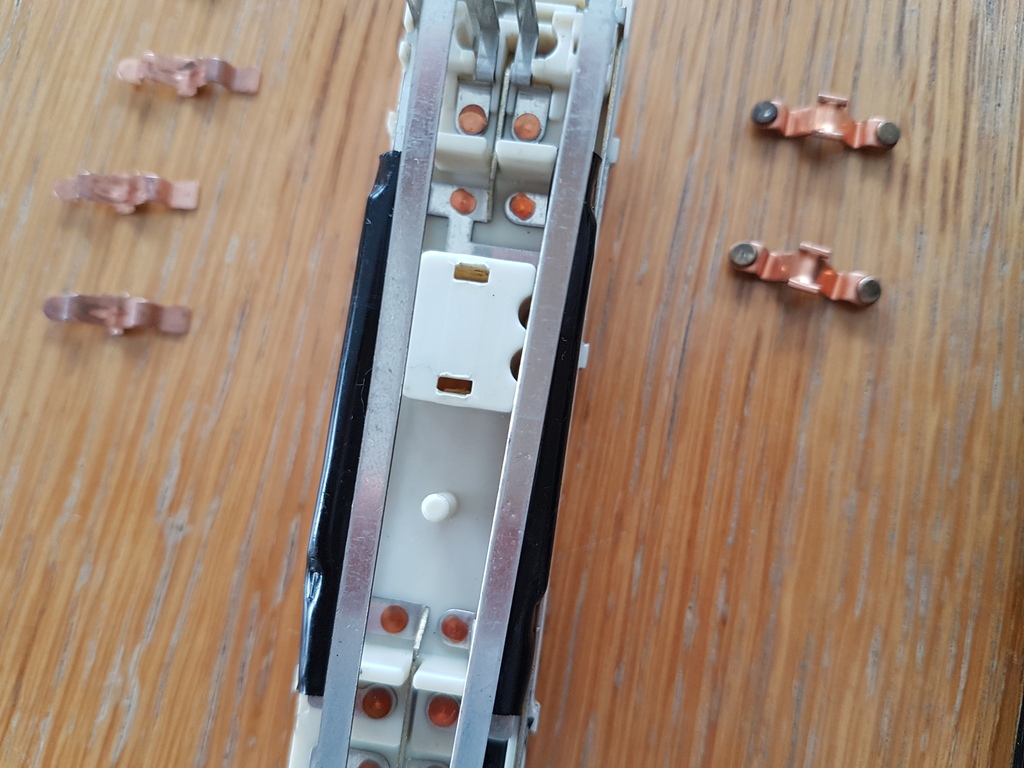
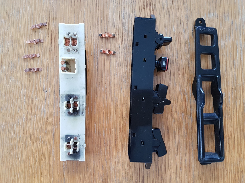
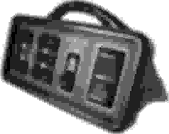
The original driver side armrest door switch , like the one you guys are showing, is what this girl came with.
The plastic part that holds the door lock switch to the housing broke off.
I searched everywhere for this switch and could not find one .
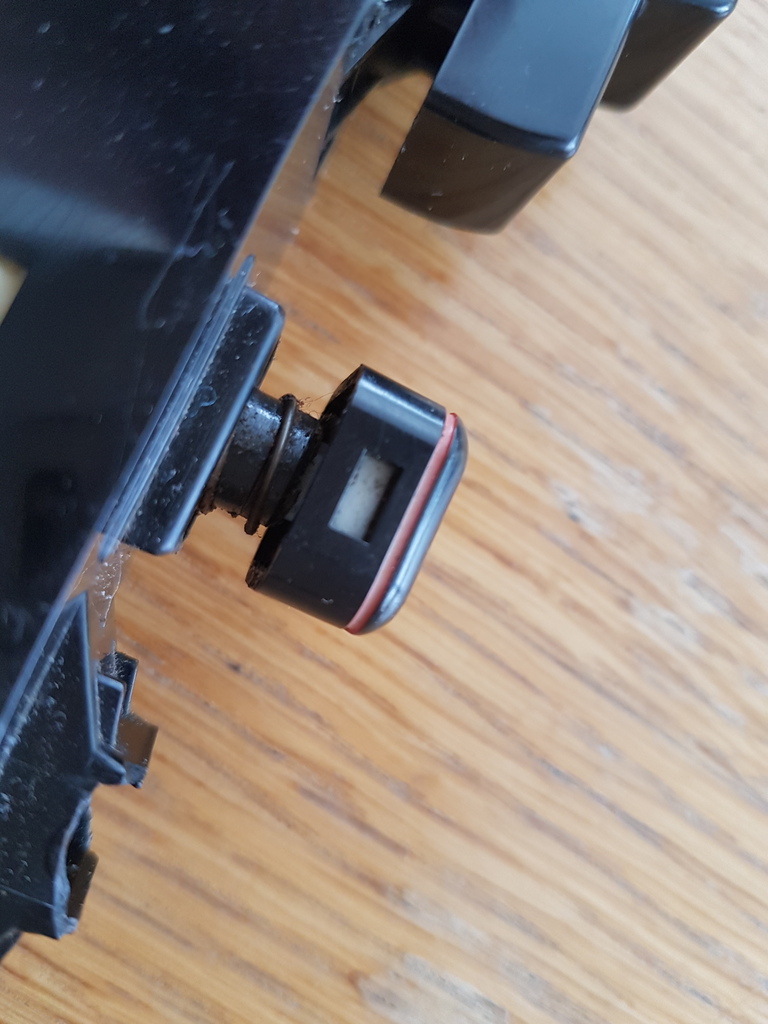
I ended up buying an aftermarket door mounted switch, the one that is more square and not as rare (It was the one on my 87 4 Runner I had years ago)
The problem I am having is that the wiring harness female connection is a different pin configuration, and wire colors are different on the male switch harness.
I have the wiring description for what each stock wire is for.
I have looked, and cant find the wiring description and pin configuration
The rewiring instructions I got from the distributor online are very strange (but this is the 1st time I have ever done anything more than just Positive and Negative wiring)
Each connector is a different shape and pin configuration.
The stock wiring harness has 2 rows of connections. 10 pin holes total with 8 active leads.and 2 blank holes. (rectangle connection)
4 holes on one row with the first and last holes as the only two active leads. the middle 2 holes between the leads are blank.
2 holes, locking mechanism (which takes up space of about 2 holes) 2 holes so the configuration is .1 active, 1 blank,locking bracket, 1 blank, 1 active
The bottom row has 6 holes total, all filled with leads.
The male connection for the after market switch has 2 rows of connections. 8 pin holes total no blank spaces (still rectangle shaped, but more squarish)
.... I have the wiring description for what each stock wire is for.
I have looked, and cant find the wiring description and pin configuration
The rewiring instructions I got from the distributor online are very strange (but this is the 1st time I have ever done anything more than just Positive and Negative wiring)
... The bottom row has 6 holes total, all filled with leads. ...
So, what is your question?
First, connectors don't have a "top" or "bottom" or "left." The pins ARE numbered, but it sounds like you don't have the manual that shows the numbered drawing. So if you want to describe the connector without using a labeled photo, you first need to say whether you are looking INTO the switch or the harness. Then don't use "top", use "locking tab side." Also, give all the wire colors of the stock harness; if you make a mistake on your call out someone with an EWD may be able to figure it out. (Most, but not all, of the wires have a colored stripe, too.)
You state you have documentation of your after-market switch. Even if it is strange to you, it is secret to the rest of us. You must have the schematic of your new switch, new connector, and all the wire colors. (No, the photos you included don't tell anyone anything.)
Do you still have the stock (broken) switch? You can probably un-pin that connector body. If you're really lucky, the new connector will have the same pins, even though the body is different. Then it's just a matter of pulling the pins out of the "new" connector body and putting them in the "old" body. If the pins aren't the same, they are available after market. You can cut off the "new" connector, crimp on pins to match the old connector body, and you'll have a good-as-factory wiring job. (Nobody wants to look at a bee's nest of crimp splices.)
Thank you for your prompt reply back. Above (in my last post) are the pages I received to rewire after market switch
pin 1 GREEN
pin 2 Green w/Blue Stripe
pin 3 Blue w/Black Stripe
pin 4 Red
pin 5 Red wi/Blue Stripe
Pin 6 Thicker Gauge Solid Blue (same color Blue as Pin 7)
pin 7 Thinner Gauge Solid Blue (same color Blue as Pin 6)
pin 8 White W/Black Stripe
The Wire Harness (Toyota Stock)
pin 1 White W/Black Stripe
pin 2 (Blank)
pin 3 (blank)
pin 4 Blue W/ Red stripe
pin 5 Blue
pin 6 Blue W/Black Stripe
pin 7 Brown W/ White Stripe
pin 8 Pink W/ White Stripe
pin 9 Blue W/ White Stripe
pin 10 Blue W/ Yellow Stripe
Sorry my question was not more concise.
I am looking for the switch wiring description as to what each control.
Who ever owned the car before me hacked the harness , as well as everything else.
They placed the long switch that this thread started on.
But some of the pins don't line up.
I tried using the old switch as a guide but some pins don't connect to anything.
As you can see the harness has 10 pins and the switch has 8 pins so the connections are different
Well, your colors don't match either my '94 EWD, or the '89 EWD. In '89, there was an 8 pin connector. The 10 pin connector used in '94 has two UNUSED pins, so it's still all controlled by 8 wires.
Here are some shots of the '89 EWD:
So you're just going to need to test the wires to see which are which. It shouldn't be too hard. First, find the 12v line, probably L-R (L is bLue). Don't put your ohmmeter on 12v; modern meters are protected, but it's bad practice to abuse your meter. With your ohmmeter, find ground (probably W-B). Find the PAIRS of pins that go to the window motors. The remaining two pins go to the Door Control Relay; ground each one in turn locks or unlocks (and so they might have 12v on them, complicating matters slightly.)

 Apr 16, 2017 | 04:24 AM