dropzone's notebook of ideas, links, mods, misc BS
 Feb 16, 2009 | 08:20 AM
#1
dropzone's notebook of ideas, links, mods, misc BS
**Update 7/10/2017: PHOTOBUCKET CHANGED THEIR TERMS AND WANT $400 A YEAR FOR PIC HOSTING. Some pics in this thread are gone forever***
OK, so I am stealing this idea from another Oregon wheeler 'Mr Stubs'.
the idea comes from a very informative thread on another forum getting gutted when one member had a bad day and deleted some of the best toyota information on the web.
I have tried bookmarking threads, emailing links to myself to save ideas for another day and always loose that info for one reason or another so I am copying Stubs idea and using this thread to store that sort of junk for me to find later.
this is stuff that I have found that may be useful to me, feel free to use the links but as always use at your own risk. we are responsible for the work we do/have done to our trucks.
sources of this stuff comes from all over the web to include: Pirate, TTora, 4x4wire, Ih8ud & vender's websites etc. I will try to give credit where credit is due.
Edit: I guess I will try to organize this thing a little better with a separate section for suspension, engine, general links etc...
[SIZE="2"]If you have found a company that was great, a link that you feel would be useful or any other Toyota related services please email or PM the info to me and I will add it[/SIZE]
Last edited by dropzone; Jul 10, 2017 at 11:12 AM.
Feb 16, 2009 | 08:26 AM
#2
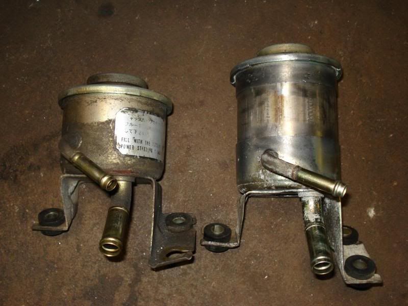
increase Power steering fluid reservoir capacity
txzuk1988:
Not sure what the toy factory reservoir capacity is. But I used it stock with a stock mini truck pump for a while. I simply cut the reservoir in half and added some exhaust tubing to make the tank about 8" tall. Here is the 3.5" exhaust pipe I used 409 SS
more reservoir Information:
From Crash:
Power Steering Cavitation--T-G PS pump
possible solutions:
http://www.quadratec.com/products/56112_5000.htm
Not sure what the toy factory reservoir capacity is. But I used it stock with a stock mini truck pump for a while. I simply cut the reservoir in half and added some exhaust tubing to make the tank about 8" tall. Here is the 3.5" exhaust pipe I used 409 SS
more reservoir Information:
From Billavista's paper:
" 3. Reservoirs
3-1. Reservoirs.
A reservoir stores a liquid that is not being used in a hydraulic system. It has many other important functions too:
* It also allows gases to expel and foreign matter to settle out from a liquid.
* It functions as a cooler
* It functions as a "coarse strainer", providing sedimentation of impurities
* It functions as an air and water separator
* It functions as a foundation for pumps etc.
a. Construction. A properly constructed reservoir should be able to dissipate heat from the oil, separate air from the oil, and settle out contaminates that are in it. Reservoirs range in construction from small steel stampings to large cast or fabricated units. The large tanks should be sandblasted after all the welding is completed and then flushed and steam cleaned.
b. Shape. Design features of a reservoir. It should be high and narrow rather than shallow and broad. The oil level should be as high as possible above the opening to a pump's suction line. This prevents the vacuum at the line opening from causing a vortex or whirlpool effect, which would mean that a system is probably taking in air. Aerated oil will not properly transmit power because air is compressible. Aerated oil has a tendency to break down and lose its lubricating ability. To increase the ability of the tank to separate dirt and water, the bottom must be slightly inclined (deepest end opposite the inlet/outlet end). An ordinary cock (without handle) is fitted so that impurities can easily be drained off. Increased separation of the air that is always present in the oil can be obtained by fitting an inclined coarse metal strainer (approx. 25-50 mesh/ inch) by the return line. Both suction and return pipes must be cut diagonally. The ends of the pipes must be located 2-4 times the pipe diameter above the bottom of the tank, partly to avoid foaming at the return line, and partly to prevent air from being drawn into the suction line, especially when the vehicle/vessel heels over to one side.
c. Size. A reservoir must be large enough so that it has a reserve of oil with all the cylinders in a system fully extended. An oil reserve must be high enough to prevent a vortex at the suction line's opening. A reservoir must have sufficient space to hold all the oil when the cylinders are retracted, as well as allow space for expansion when the oil is hot. A common-size reservoir on a mobile machine is a 20- or 30-gallon tank used with a 100- GPM system. Many 10-GPM systems operate with 2- or 3-gallon tanks because these mobile systems operate intermittently, not constantly. For stationary machinery, a rule of thumb is that a reservoir�s size should be two to three times a pump�s output per minute. A large size tank is highly desirable for cooling. The large surface areas exposed to the outside air transfer heat from the oil. Also, a large tank helps settle out the contaminates and separates the air by reducing recirculation. If the application is mobile, if there is no cooler built into the system, and provided the tank is located where air circulation is good, ideally the size of the tank should be approx. 2-3 times the capacity of the pump per minute.In our 4x4 systems we are unlikely to be able to achieve such large reservoir capacities as this, but the important lesson is that your reservoirs cannot be too big - it is best to use the largest possible reservoir space and weight restrictions allow."
Further down, it states this:
" f. Line Connections. A pump suction and a tank's return lines should be attached by flanges or by welded heavy-duty couplings. Standard couplings usually are not suitable because they spread when welded. If a suction line is connected at the bottom, a coupling should extend well above the bottom, inside the tank; residual dirt will not get in a suction line when a tank or strainer is cleaned. A return line should discharge near a tank's bottom always below the oil level. A pipe is usually cut at a 45-degree angle and the flow aimed away from a suction line to improve circulation and cooling. A baffle plate is used to separate a suction line from a return line. This causes the return oil to circulate around an outer wall for cooling before it gets to the pump again. A baffle plate should be about two-thirds the height of a tank. The lower corners are cut diagonally to allow circulation. They must be larger in area than a suction line's cross section. Otherwise the oil level between a return and a suction side might be uneven. Baffling also prevents oil from sloshing around when a machine is moving. Many large reservoirs are cross-baffled to provide cooling and prevent sloshing."
From here: http://www.pirate4x4.com/tech/billav...ng/index1.html
Good luck.
Al
Ok, there is one thing that you really need ... some way to keep the p/s fluid temp down. Since I am going to tap the steering box for hydro assist, that will help with keeping the temps down a little, but a cooler is still needed. Unfortunately there is just NO room down low (You always need to make sure your reservior is the highest point or fluid will drain back and overfill the res.) to mount the cooler easily. I finally ended up mouting it to the battery tray...


I just finished building my truck and installed the TG Power steering pump, resevoir, and cooler. I tapped my own PS box and used a 6" stroke 1 1/2" PSC Ram. I am using royal purple synthetic PS fluid. I bled everything real well and the system was working good. I took it for a ride today and the steering got progressivly worse. I had it ideling and opened the resevoir to see a small vortex drawing air occasionally. With the truck off the large resy is filled up to the welded seam. Does anyone have any suggestions or experience with this? I've read about this issue with stock resevoirs but the problem went away when the installed a larger one or increased capacity. Thanks
Last edited by dropzone; May 28, 2009 at 12:00 AM.
Feb 16, 2009 | 07:00 PM
#3
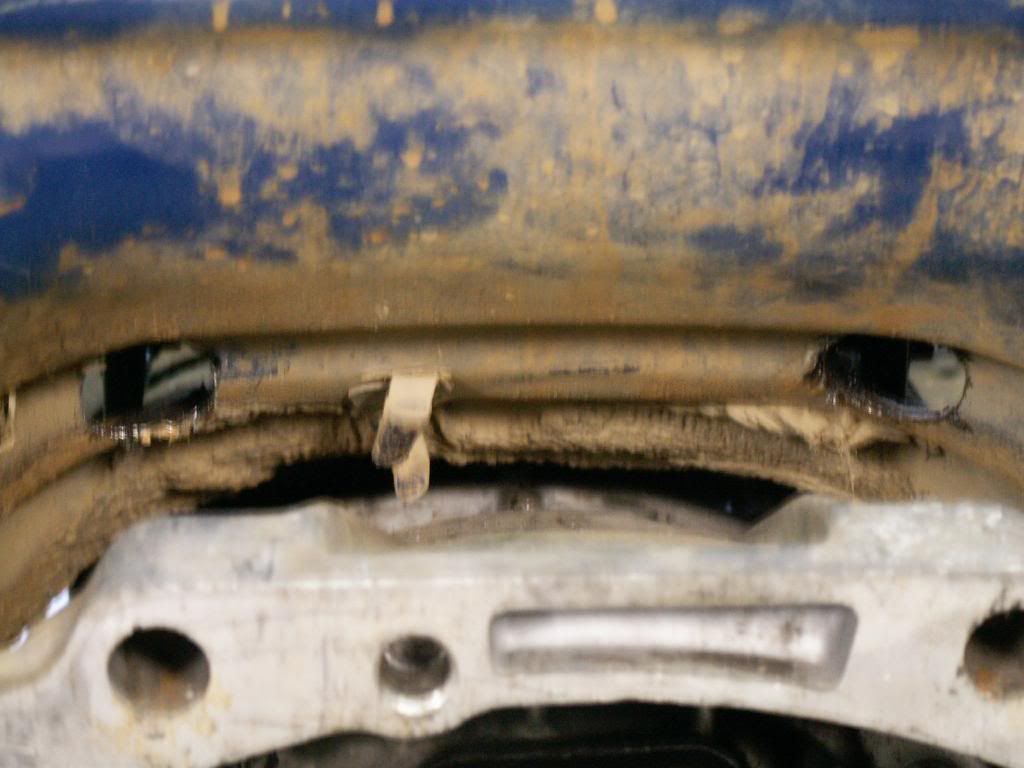
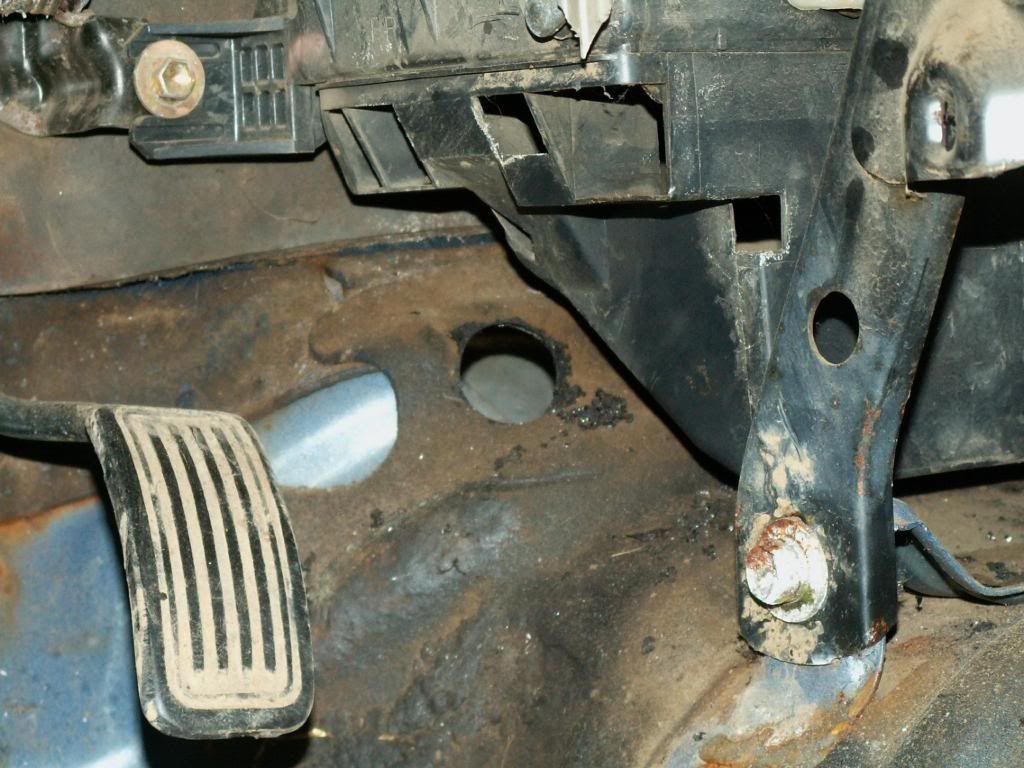
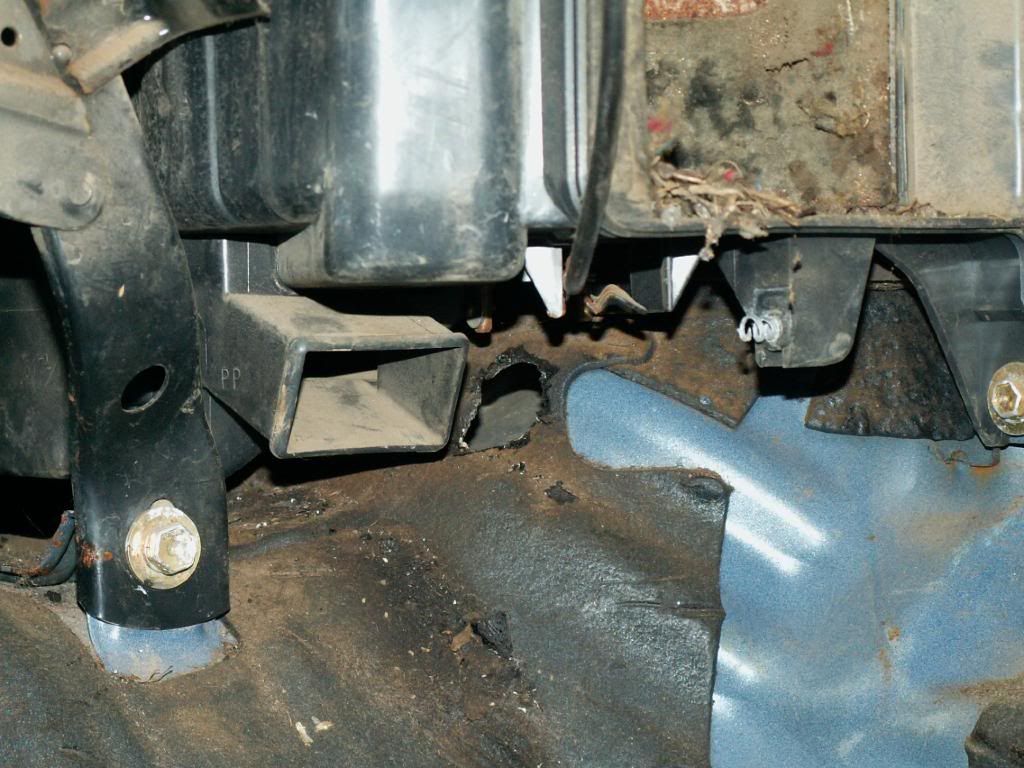
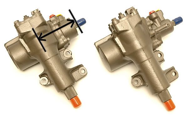
Mounting Box for High steer and Steering Box Info
The IFS box mount is pretty simple. Cut the fender well so you can easily access the PS box area like shown in my pictures posted already and then push the box all the way forward until it is on the core. Angle it so the holes line up on the frame in the center and then test fit your mounting plates. Tack weld and test fit again to make sure the pitman arm clears and weld out.


what you don't want to have happen when you install your high steer:


Power steering box rebuilding:
http://web.archive.org/web/200503220.../taco/box.html
will aad some more info on steering box stuff here--
great link on rebuilding your steering box: http://web.archive.org/web/200503220.../taco/box.html
tapping your box for hydro assist http://board.marlincrawler.com/index.php?topic=10579.0
just in case you take a steering box apart too far--great write up
Found this on ttora in this thread:
http://ttora.com/forum/showthread.php?t=146872
Well, this is my first technical post so I will try to put this together in a way that should be pretty simple to follow;
Earlier today I tore apart an '87 Toyota IFS steering box from a 4Runner to start tapping the case for hydro assist stearing. Well, I was blessed with the opportunity to experience the frustration of many before me who have experienced the miss hap of pulling the worm gear from its piston and the 43 bearings (yes, I counted) snugged away inside pour out to their freedom. Thankfully I had the shaft pointed up and the bearing fell into its own housing.
**Just as a note, if you are seperating your steering box for hydro assist plumbing, you DO NOT have to pull the worm shaft out!! Once you've backed out the 10mm hex centering shaft cover, pull it out with channel locks if it doesn't want to come the rest of the way out, a spring will follow and behind that is the centering shaft which must come out or your piston won't slide out. This is where I screwed up and didn't realize the shaft was still in there, so I pulled the worm gear to see what was wrong and got myself in a pickle.**
So here are the puzzle pieces; Worm gear with spline shaft, Worm gear piston, and 43 bearings.


This tube acts as a channel that the bearings travel through while the piston rides up and down on the shaft. It has to be removed with a phillip's head screwdriver and it will come out rather easily and is split down the middle;


cont...
Next, thread the shaft back into the piston until the threads start to appear at the at the lower port for the tube. You won't be able to get the bearings back in with the shaft all the way home as you need to work it in and let gravity help you a little bit to get the bearings settled in;


I used the tang end of a file to help push the bearings in and found that turning the shaft back n forth a little helped sit them in.
Make sure the bearings sit "down" into the shaft and don't ride up to the top of the piston or they'll start plopping out. And, don't let them ride down into the piston past the lower port or they will find their way into the bottom of the piston and you'll have to back the shaft out and start over!


Here you can see that there are as many bearings now in side that are going to fit. BUT, there are quite a few left over, exactly enough to fit inside the tube.


How am I going to get them to stay inside the tube with out them going all over when I pick it up to put it back in place on the piston...?
cont...
VASELINE!!
I didn't want to use gear lube cause I figured it would be too thick and maybe end up with a fluid flow issue. I'm guessing the vaseline is light enough that it'll liquify pretty quick and blend in with the power steering fluid pretty easily. And, I probably didn't have to use as much as I did either. Some at each end of the tube would have worked just as well. I tried this once without the vaseline and the bearings spilled uncontrollably and jammed up the ports so that I could not sink the tube so I had to fish the bearings out to try again;


After the tube is in place, put the strap over it and put the screws in. Test the travel of the shaft a couple of times and if it feels like it is riding well, tighten the screws the rest of the way. You cannot afford to have them backing out;


Easiest way I found to see if the bearings were sitting well was to let gravity do it's work. I pulled the shaft out some of the way (NOT TOO MUCH OR YOU"LL LOSE THE BEARINGS AGAIN) and just let the weight of it pull itself down onto the piston. If it rides down without binding or stalling you've completed the task;
http://yfrog.us/jpwormgearbearings011z
Yer back in buisness!!
Pitman Arms - Dimension of other arms
http://www.pirate4x4.com/forum/showthread.php?t=593367
http://www.pirate4x4.com/forum/showthread.php?t=294202
Pitman Arm Removal / Swap - How to
http://www.pirate4x4.com/forum/showthread.php?t=511091
[Power Steering Box - Info
How to rebuild it
http://web.archive.org/web/200503220.../taco/box.html
Steering Box rebuild kit PN 04455-35080
http://www.pirate4x4.com/forum/showthread.php?t=587519
How to Tap it for Hydro Assist
http://www.wildyoats.com/hydraulic_assist_tech.htm
http://board.marlincrawler.com/index.php?topic=10579.0
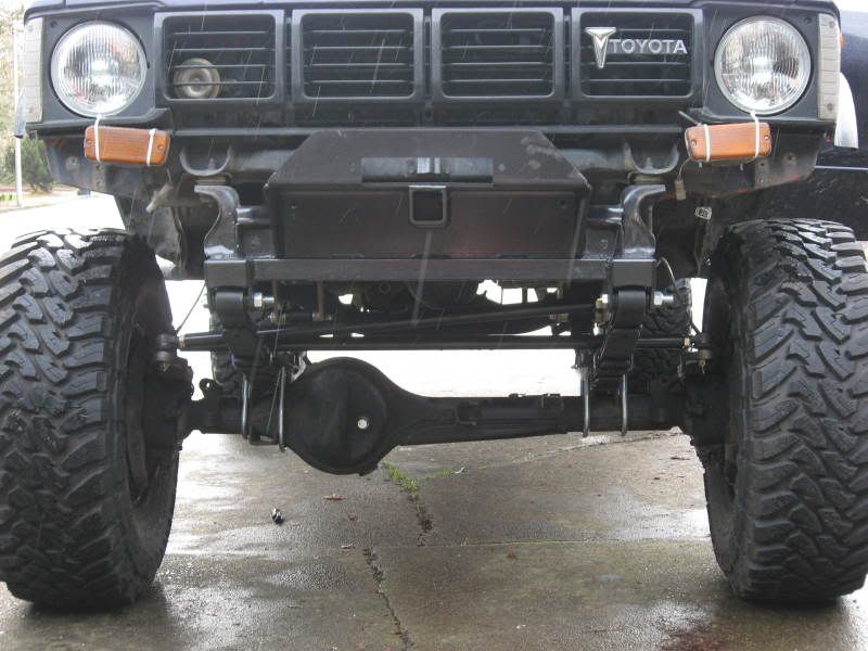
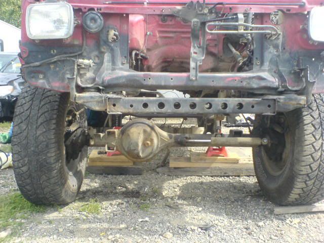
Power Steering Box Location, Moving it Forward by Bones
Since this has been on numerous threads, I may as well post it here. Here's an IFS steering box moved as far forward as I could (2.5"~) and hacked the radiator support to boot. Ref: http://www.pirate4x4.com/forum/showt...t=steering+box
More pictures of mounting the power steering IFS boxes here:
http://www.pirate4x4.com/forum/showthread.php?t=587517
http://www.pirate4x4.com/forum/showthread.php?t=424669
Power steering box identification
http://www.pirate4x4.com/forum/showthread.php?t=587515
Power Steering Box AN-Fittings
http://www.pirate4x4.com/forum/showthread.php?t=617050
High Pressure Port - 16 x 1.5 MM Inverted Flare to #6 JIC Male adapter, Toyota - 'PSC Motorsports' #PSC-SF06 or 'Summit Racing' #EAR-9919DFJERL
Low Pressure Port - 17 x 1.5 MM Inverted Flare to #6 JIC Male adapter, Toyota - 'PSC Motorsports' #PSC-SF07
Power Steering Flush
http://www.pirate4x4.com/forum/showthread.php?t=588900
Power Steering Hose Part Numbers- Stock Application-
Stock power steering high pressure hose PN's:
'85 4WD NAPA: NPS73354 $27.99
VATO Zone: 71260 $25.99
'83 4WD VATO Zone: 71171 $25.99
Schucks: 71171 $37.93
The difference's between the two are the '83 has a 45 degree bend and long stem into the box and a 90 degree bend on the pump end and the '85 has a short 90 on the box side and two oposing 90's on the pump side
Power Steering Pump Mod - Removing the restrictor plate
http://www.pirate4x4.com/forum/showt...hreadid=167299
http://board.marlincrawler.com/index.php?topic=10579.0
Power Steering Pump - High Flow TC style mounting
http://www.pirate4x4.com/forum/showthread.php?t=571624
http://www.pirate4x4.com/forum/showthread.php?t=630765
Power Steering Reservior
www.Speedwaymotors.com has a power steering resivoir that is a perfect fit for this set up. $24.95
It is P/N 91032876-STD-10. It has a -6 inlet and a -10 outlet.
this fits the power steering pump inlet well.
Tripling the size of the Toyota power steering reservoir
http://www.pirate4x4.com/forum/showthread.php?t=579700
http://www.pirate4x4.com/forum/showthread.php?t=593367
http://www.pirate4x4.com/forum/showthread.php?t=294202
Pitman Arm Removal / Swap - How to
http://www.pirate4x4.com/forum/showthread.php?t=511091
[Power Steering Box - Info
How to rebuild it
http://web.archive.org/web/200503220.../taco/box.html
Steering Box rebuild kit PN 04455-35080
http://www.pirate4x4.com/forum/showthread.php?t=587519
How to Tap it for Hydro Assist
http://www.wildyoats.com/hydraulic_assist_tech.htm
http://board.marlincrawler.com/index.php?topic=10579.0
Power Steering Box Location, Moving it Forward by Bones
Since this has been on numerous threads, I may as well post it here. Here's an IFS steering box moved as far forward as I could (2.5"~) and hacked the radiator support to boot. Ref: http://www.pirate4x4.com/forum/showt...t=steering+box
More pictures of mounting the power steering IFS boxes here:
http://www.pirate4x4.com/forum/showthread.php?t=587517
http://www.pirate4x4.com/forum/showthread.php?t=424669
Power steering box identification
http://www.pirate4x4.com/forum/showthread.php?t=587515
Power Steering Box AN-Fittings
http://www.pirate4x4.com/forum/showthread.php?t=617050
High Pressure Port - 16 x 1.5 MM Inverted Flare to #6 JIC Male adapter, Toyota - 'PSC Motorsports' #PSC-SF06 or 'Summit Racing' #EAR-9919DFJERL
Low Pressure Port - 17 x 1.5 MM Inverted Flare to #6 JIC Male adapter, Toyota - 'PSC Motorsports' #PSC-SF07
Power Steering Flush
http://www.pirate4x4.com/forum/showthread.php?t=588900
Power Steering Hose Part Numbers- Stock Application-
Stock power steering high pressure hose PN's:
'85 4WD NAPA: NPS73354 $27.99
VATO Zone: 71260 $25.99
'83 4WD VATO Zone: 71171 $25.99
Schucks: 71171 $37.93
The difference's between the two are the '83 has a 45 degree bend and long stem into the box and a 90 degree bend on the pump end and the '85 has a short 90 on the box side and two oposing 90's on the pump side
Power Steering Pump Mod - Removing the restrictor plate
http://www.pirate4x4.com/forum/showt...hreadid=167299
http://board.marlincrawler.com/index.php?topic=10579.0
Power Steering Pump - High Flow TC style mounting
http://www.pirate4x4.com/forum/showthread.php?t=571624
http://www.pirate4x4.com/forum/showthread.php?t=630765
Power Steering Reservior
www.Speedwaymotors.com has a power steering resivoir that is a perfect fit for this set up. $24.95
It is P/N 91032876-STD-10. It has a -6 inlet and a -10 outlet.
this fits the power steering pump inlet well.
Tripling the size of the Toyota power steering reservoir
http://www.pirate4x4.com/forum/showthread.php?t=579700
Last edited by dropzone; Dec 9, 2011 at 05:18 AM.
Feb 16, 2009 | 07:08 PM
#4
Feb 16, 2009 | 07:21 PM
#5
thread links
Google for TOyota Websites
Flat Bed Pics:
http://www.pirate4x4.com/forum/showt...ferrerid=89727
Toyota Front Bumper pics
http://pirate4x4.com/forum/showthrea...t=front+bumper
Great info On color schemes etc:
Toyota Reference.com
SR-5 Info
SR-5.com
Service Manual Links:
http://ncttora.com/fsm/index.html
4Crawler Off Road Toyota CHeap Tricks
Rear Disk Conversion Links/Help:
http://www.pirate4x4.com/forum/showt...ferrerid=89727
--Proportioning Valve http://www.pirate4x4.com/forum/showt...ferrerid=89727
--Dave'z Offroad Performance Rear Disk Conversion kit:
http://www.davezoffroadperformance.c...c.php?f=3&t=52
Steering Box Rebuilding:
http://www.pirate4x4.com/forum/showt...ferrerid=89727
Power Steering Pump Rebuilding
http://www.toy4x4.net/ps/index.htm
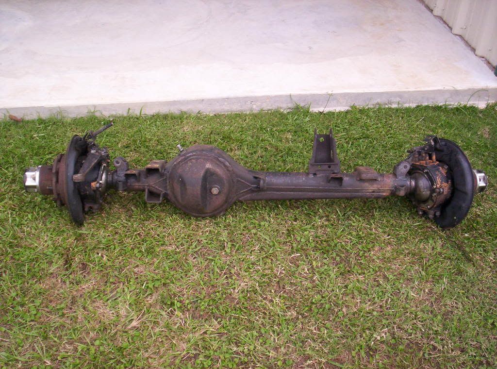
Axle Info
Axle info - Toyota
Toyota Mini Truck Front Axle Identification
79-80 no gusset
81-83 short gusset (to u-bolts)
84-85 long gusset (past u-bolts)
Stock Toyota front axle measurements for comparison:
55.5" wide, 29" spring perch centers, '79-85 Toyota trucks and 4runners, SA Hubs
58.25" wide, 29" spring perch centers, '79-85 Toyota trucks and 4runners, IFS Hubs
63.5" wide, (set up for coil springs) 90-97 FJ80 and FZJ80 Landcruisers
'86-95 IFS front end is about 58.5" wide
'93-98 T100 IFS front end is about 65" wide
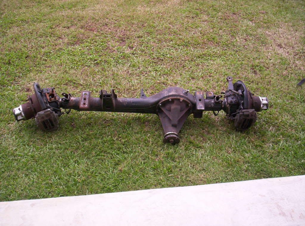
Toyota Rear Axle Widths:
55" wide, '79-85 4wd trucks/4runners - 6 Lug
58" wide, '86-95 4wd trucks/4runners - 6 Lug
56" wide, '79-95 2wd Trucks - 5 Lug
60.75" wide, '95.5-up Tacomas/4runners
66.75" wide, '93-98 T100 trucks
Identifying Toyota Third Members:
http://home.4x4wire.com/erik/diffs/
Find your factory Gear Ratio using your VIN
http://www.brian894x4.com/Gearratiosanddiffs.html
More Differential Information:
"LPH" (Long Pinion Head) vs "SPH" (Short Pinion Head). by Drew Persson
http://www.pirate4x4.com/forum/showt...23#post1478223
Myth Settled: 8.4, V6, 4cyl, ALL 8" - by Brian Ellinger
http://www.pirate4x4.com/forum/showt...hreadid=228681
Pluging ABS sensor hole in late model diffs
http://www.pirate4x4.com/forum/showthread.php?t=587522
Toyota 4 pinoin 6 cylinder 8" diff (30 spline)
http://www.4crawler.com/4x4/Images/Diff6cyl.jpg
Toyota Land cruiser high pinion 8" diff (30 spline)
http://www.4crawler.com/4x4/Images/DiffHP.jpg
Toyota 4 pinion 6 cylinder 8" 3rd from a '96-00? 4Runner (30 spline)
http://www.pirate4x4.com/forum/attac...&postid=436184
Differential Mounting Differences Between Different 3rd Members
http://www.pirate4x4.com/forum/showt...52#post5331552
ID Toyota Mini Truck axles
79-80 no gusset
81-83 short gusset (to u-bolts)
84-85 long gusset (past u-bolts)
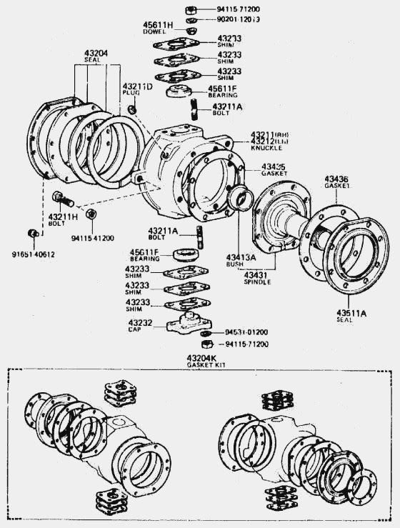
Rebuilding Front Straight Axle:
http://www.birfield.com/~morgan/tech/axle/
http://www.4crawler.com/4x4/CheapTri...eRebuild.shtml
http://www.lukemiller.org/toys/1985_...t_axle_FSM.pdf
Rebuilding Aisin Manual Hubs:
https://www.yotatech.com/forums/f116...ferrerid=12218
Power Steering Cooler Recommendations
http://www.tacomaterritory.com/forum...teering+cooler
Suspension links
Toyota Rear Springs up front (RUF)
http://pirate4x4.com/forum/showthrea...&highlight=faq
63" Chevy Spring Conversions: http://pirate4x4.com/forum/showthrea...ight=chevy+faq
Transfer Case Info
Trail-Gears TC Videos:
t-case: http://www.trail-gear.com/videos/toy-tcase.wmv
Dual case: http://www.trail-gear.com/videos/toydualcase.wmv
Transmission and other Transfer case info: http://www.4x4wire.com/toyota/faq/parts/
Marlin transmission info: http://marlincrawler.com/transmission/rebuilt-complete
4.7 gear install (Kiwi found something the pro's were not aware of )
)
pretty cool when Marlin's kid notices your fix:
Rear Differential Breather Extension:
https://www.yotatech.com/forums/f129...her-mod-75747/
TTORA FAQ and TOyota Knowledge Base LINK: http://www.ttora.com/wiki/index.php/Main_Page
IH8Mud's Toyota TAQ: http://forum.ih8mud.com/79-95-toyota...questions.html
YotaTech tech Write Ups
Roger Browns AKA 4Crawlers info (some great stuff) he covers just about anything you can think of
4Runner: http://www.4crawler.com/4Runner.shtml
Cheap Tricks: http://www.4crawler.com/4x4/CheapTri...#MODIFICATION$
Drive Shaft Info
General DS info
Building a Square Front Driveshaft
Flat Bed Pics:
http://www.pirate4x4.com/forum/showt...ferrerid=89727
Toyota Front Bumper pics
http://pirate4x4.com/forum/showthrea...t=front+bumper
Great info On color schemes etc:
Toyota Reference.com
SR-5 Info
SR-5.com
Service Manual Links:
http://ncttora.com/fsm/index.html
4Crawler Off Road Toyota CHeap Tricks
Rear Disk Conversion Links/Help:
http://www.pirate4x4.com/forum/showt...ferrerid=89727
--Proportioning Valve http://www.pirate4x4.com/forum/showt...ferrerid=89727
--Dave'z Offroad Performance Rear Disk Conversion kit:
http://www.davezoffroadperformance.c...c.php?f=3&t=52
Steering Box Rebuilding:
http://www.pirate4x4.com/forum/showt...ferrerid=89727
Power Steering Pump Rebuilding
http://www.toy4x4.net/ps/index.htm
Axle Info
Axle info - Toyota
Toyota Mini Truck Front Axle Identification
79-80 no gusset
81-83 short gusset (to u-bolts)
84-85 long gusset (past u-bolts)
Stock Toyota front axle measurements for comparison:
55.5" wide, 29" spring perch centers, '79-85 Toyota trucks and 4runners, SA Hubs
58.25" wide, 29" spring perch centers, '79-85 Toyota trucks and 4runners, IFS Hubs
63.5" wide, (set up for coil springs) 90-97 FJ80 and FZJ80 Landcruisers
'86-95 IFS front end is about 58.5" wide
'93-98 T100 IFS front end is about 65" wide
Toyota Rear Axle Widths:
55" wide, '79-85 4wd trucks/4runners - 6 Lug
58" wide, '86-95 4wd trucks/4runners - 6 Lug
56" wide, '79-95 2wd Trucks - 5 Lug
60.75" wide, '95.5-up Tacomas/4runners
66.75" wide, '93-98 T100 trucks
Identifying Toyota Third Members:
http://home.4x4wire.com/erik/diffs/
Find your factory Gear Ratio using your VIN
http://www.brian894x4.com/Gearratiosanddiffs.html
More Differential Information:
"LPH" (Long Pinion Head) vs "SPH" (Short Pinion Head). by Drew Persson
http://www.pirate4x4.com/forum/showt...23#post1478223
Myth Settled: 8.4, V6, 4cyl, ALL 8" - by Brian Ellinger
http://www.pirate4x4.com/forum/showt...hreadid=228681
Pluging ABS sensor hole in late model diffs
http://www.pirate4x4.com/forum/showthread.php?t=587522
Toyota 4 pinoin 6 cylinder 8" diff (30 spline)
http://www.4crawler.com/4x4/Images/Diff6cyl.jpg
Toyota Land cruiser high pinion 8" diff (30 spline)
http://www.4crawler.com/4x4/Images/DiffHP.jpg
Toyota 4 pinion 6 cylinder 8" 3rd from a '96-00? 4Runner (30 spline)
http://www.pirate4x4.com/forum/attac...&postid=436184
Differential Mounting Differences Between Different 3rd Members
http://www.pirate4x4.com/forum/showt...52#post5331552
ID Toyota Mini Truck axles
79-80 no gusset
81-83 short gusset (to u-bolts)

84-85 long gusset (past u-bolts)
Rebuilding Front Straight Axle:
http://www.birfield.com/~morgan/tech/axle/
http://www.4crawler.com/4x4/CheapTri...eRebuild.shtml
http://www.lukemiller.org/toys/1985_...t_axle_FSM.pdf
Rebuilding Aisin Manual Hubs:
https://www.yotatech.com/forums/f116...ferrerid=12218
Power Steering Cooler Recommendations
http://www.tacomaterritory.com/forum...teering+cooler
Suspension links
Toyota Rear Springs up front (RUF)
http://pirate4x4.com/forum/showthrea...&highlight=faq
63" Chevy Spring Conversions: http://pirate4x4.com/forum/showthrea...ight=chevy+faq
Transfer Case Info
Trail-Gears TC Videos:
t-case: http://www.trail-gear.com/videos/toy-tcase.wmv
Dual case: http://www.trail-gear.com/videos/toydualcase.wmv
Transmission and other Transfer case info: http://www.4x4wire.com/toyota/faq/parts/
Marlin transmission info: http://marlincrawler.com/transmission/rebuilt-complete
4.7 gear install (Kiwi found something the pro's were not aware of
)So, I put some 4.7 gears in My single, forward shift, T-case yesterday. I've worked on lots of New Process cases but never a toyota case, so I actually read the directions..........that was My downfall.
When you read the directions, You dont really watch what's going on because You're depending on the step by step directions to guide You, plus looking at the cool pictures.
So I clearanced the case for the new oversized gear. I fit the gear in place and all looked good

I also clearanced the shift fork/dog for Low gear, just like the pictures tell You to do.
I put the whole thing back together, and thats when I found out that as soon as I put the case in low gear on the bench, that it locked up.
So, of course I just added some more force to fix the problem. Well, when I did that it would make a ty noise and then would jump out of low gear. WTF.
I pull the whole thing apart to trace the problem down. And now for the stupid part.
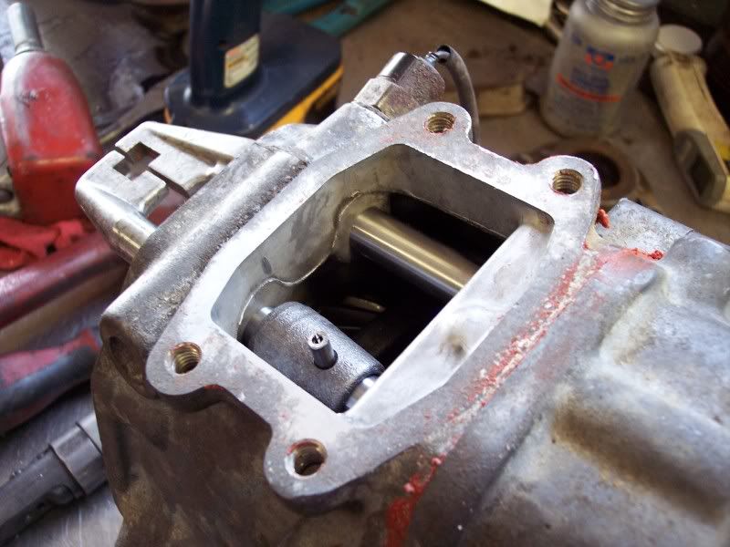
The directions say to clearance the low gear shift fork down, but they dont tell You to grind the roll pin for that fork down, or dont drive it all the way home. Because if You dont shorten that roll pin or do drive it down all the way........Guess what?
It then hits the in new oversized gear and locks Your Up!
This is the pin in question after shortening it.
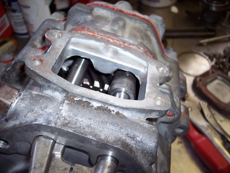
In low gear, after the fix.
I hope this helps some other Noob, do it right the First time.
Kiwi
When you read the directions, You dont really watch what's going on because You're depending on the step by step directions to guide You, plus looking at the cool pictures.
So I clearanced the case for the new oversized gear. I fit the gear in place and all looked good
I also clearanced the shift fork/dog for Low gear, just like the pictures tell You to do.
I put the whole thing back together, and thats when I found out that as soon as I put the case in low gear on the bench, that it locked up.
So, of course I just added some more force to fix the problem
. Well, when I did that it would make a ty noise and then would jump out of low gear. WTF.I pull the whole thing apart to trace the problem down. And now for the stupid part.
The directions say to clearance the low gear shift fork down, but they dont tell You to grind the roll pin for that fork down, or dont drive it all the way home. Because if You dont shorten that roll pin or do drive it down all the way........Guess what?
It then hits the in new oversized gear and locks Your Up!
This is the pin in question after shortening it.
In low gear, after the fix.
I hope this helps some other Noob, do it right the First time.
Kiwi
Kiwipushrod,
I noticed you are installing TG gears but the same applies with our instructions in that the former employee who made the guide left that part out!
So I have updated step 49 of our installer to include this required info
http://www.marlincrawler.com/tech/gu...1-gear-install
Thanks for the tip!
Mike
I noticed you are installing TG gears but the same applies with our instructions in that the former employee who made the guide left that part out!
So I have updated step 49 of our installer to include this required info
http://www.marlincrawler.com/tech/gu...1-gear-install
Thanks for the tip!
Mike
Rear Differential Breather Extension:
https://www.yotatech.com/forums/f129...her-mod-75747/
TTORA FAQ and TOyota Knowledge Base LINK: http://www.ttora.com/wiki/index.php/Main_Page
IH8Mud's Toyota TAQ: http://forum.ih8mud.com/79-95-toyota...questions.html
YotaTech tech Write Ups
Roger Browns AKA 4Crawlers info (some great stuff) he covers just about anything you can think of
4Runner: http://www.4crawler.com/4Runner.shtml
Cheap Tricks: http://www.4crawler.com/4x4/CheapTri...#MODIFICATION$
Drive Shaft Info
General DS info
Building a Square Front Driveshaft
Last edited by dropzone; Jun 7, 2016 at 03:49 PM. Reason: fixed, added some links
Feb 16, 2009 | 07:30 PM
#6
WInch Info
I could go on for hours about this subject, so I will keep this short.
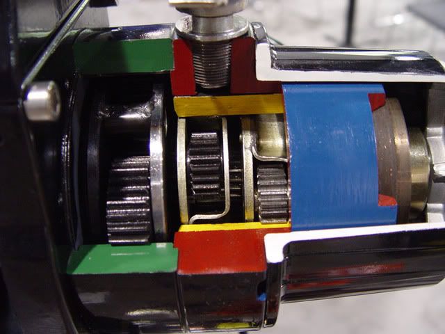
First, there are 3 basic types of winches:
Planetary:

Spur Gear:

Worm Gear:


Planetary winches are a great option for the recreational 4x4 enthusiast. They are relatively affordable, and perform well under occasional use. Although the quality varies the greatest among this sector.
The other types of winches are Spur Gear, and Worm Gear winches. These are industrial winches. If your going to use your winch 5, 10, 50 times a day, buy a Spur or Worm Drive winch. Also notice that I showed pictures of almost every winch in this market. The Ramsey shown is almost identical to what you will find on almost every flat bed wrecking truck on the road today. The Superwinch Husky is an offroad recovery worm drive winch. Then, we all know the Warn 8274. Worm drive winches are also the only winches which are designed to power a load out.
As I mentioned, the big difference comes in the Planetary gear winches.
The largest issues with these winches come from poor build quality. Its very common to have 1 or 2 85 amp solenoids going to a 400 amp motor. Thus, the solenoids will melt. Also, the motors do not have a long duty cycle. Heat becomes a killer for these winches. Planetary drive winches use a brake to hold the load in place. Normally it does not work very well. When you power out, the brake engages, and is always pushing against the winch. Guess, what, this creates heat.
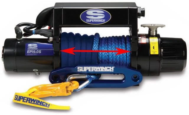
For those who like to run synthetic winch line, this heat will melt the winchline. Most winches (warn's, milemarker's, ramsey's, etc) have the brake under the winch drum. This means as you power out the winch will heat up, and melt the winch line. While most have sidestepped this issue by using fireline, it still is a problem. The only manufacturer who has an external brake, is superwinch, in their EP series winches:
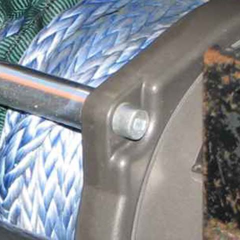
Another issue with synthetic winchline is it is very slick, thus causing it to slide in-between the underlaying layers on the winch drum. With steel cable, it is very easy to spool the cable, so it is nice and tight, avoiding this issue. Even with with best spool job, synthetic winchline will slip in-between the lower layers. This causes a very hard side-load on the winch:
On the Warn winches, it will cause the casting of the winch to snap off at the cross bars. I wish I had a good photo of when one broke on my co-worker in Maine. It made a bad situation worse.
Next is going into rating. Some manufacturers rate the winches at their stall speed and some rate their winches at their working load. So, YES one manufacturer can call a winch a 8,000, and some could call it 10,000.
I don't know if you can tell, but I have had to use ALOT of winches, and prefer Superwinch. They just seem to be built better. I have also had a lot of problems with Warn Winches. But this could also be because I have used 10 warn winches to every other winch out there. I personally feel, if you want a REALLY good winch, you should suck it up and buy a worm, or spur drive winch. I love the superwinch husky, but its stupid expensive. The Warn 8274 is awesome, but so fast, it can get unsafe. I ended up picking up a Ramsey re12000 for my current truck, because they are priced right, and short of some bad solenoids (easy to swap in superwinch solenoids), are really good winches.
Let me know what else you would like to know.
First, there are 3 basic types of winches:
Planetary:
Spur Gear:
Worm Gear:
Planetary winches are a great option for the recreational 4x4 enthusiast. They are relatively affordable, and perform well under occasional use. Although the quality varies the greatest among this sector.
The other types of winches are Spur Gear, and Worm Gear winches. These are industrial winches. If your going to use your winch 5, 10, 50 times a day, buy a Spur or Worm Drive winch. Also notice that I showed pictures of almost every winch in this market. The Ramsey shown is almost identical to what you will find on almost every flat bed wrecking truck on the road today. The Superwinch Husky is an offroad recovery worm drive winch. Then, we all know the Warn 8274. Worm drive winches are also the only winches which are designed to power a load out.
As I mentioned, the big difference comes in the Planetary gear winches.
The largest issues with these winches come from poor build quality. Its very common to have 1 or 2 85 amp solenoids going to a 400 amp motor. Thus, the solenoids will melt. Also, the motors do not have a long duty cycle. Heat becomes a killer for these winches. Planetary drive winches use a brake to hold the load in place. Normally it does not work very well. When you power out, the brake engages, and is always pushing against the winch. Guess, what, this creates heat.
For those who like to run synthetic winch line, this heat will melt the winchline. Most winches (warn's, milemarker's, ramsey's, etc) have the brake under the winch drum. This means as you power out the winch will heat up, and melt the winch line. While most have sidestepped this issue by using fireline, it still is a problem. The only manufacturer who has an external brake, is superwinch, in their EP series winches:
Another issue with synthetic winchline is it is very slick, thus causing it to slide in-between the underlaying layers on the winch drum. With steel cable, it is very easy to spool the cable, so it is nice and tight, avoiding this issue. Even with with best spool job, synthetic winchline will slip in-between the lower layers. This causes a very hard side-load on the winch:
On the Warn winches, it will cause the casting of the winch to snap off at the cross bars. I wish I had a good photo of when one broke on my co-worker in Maine. It made a bad situation worse.
Next is going into rating. Some manufacturers rate the winches at their stall speed and some rate their winches at their working load. So, YES one manufacturer can call a winch a 8,000, and some could call it 10,000.
I don't know if you can tell, but I have had to use ALOT of winches, and prefer Superwinch. They just seem to be built better. I have also had a lot of problems with Warn Winches. But this could also be because I have used 10 warn winches to every other winch out there. I personally feel, if you want a REALLY good winch, you should suck it up and buy a worm, or spur drive winch. I love the superwinch husky, but its stupid expensive. The Warn 8274 is awesome, but so fast, it can get unsafe. I ended up picking up a Ramsey re12000 for my current truck, because they are priced right, and short of some bad solenoids (easy to swap in superwinch solenoids), are really good winches.
Let me know what else you would like to know.
Ha ha. I was hoping you wouldn't ask about the Smittybilt winch. Its one of the few I have NOT used. Although, when you look at the specs next to a warn, it makes any educated buyers wonder why they would want the warn:
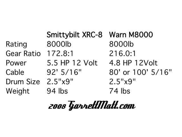
See, the specifications on the Smittybult are better! More hp, with less gearing means a faster winch, which does not slow down as much under hard pulls. Warn put in a lower hp motor, and increased the gearing to get the same 8000lb rating out of it.
Also remember the size of the drum acts as a gear too. While not an issue with the 2 winches in question, it becomes something to look at when comparing other winches on the market. Just think: Torque=ForcexDistance So the farther the cable is from the center of the pivot (the drum) the less torque is applied through the winch cable. Thus, less pulling power.

So the smaller the drum of the winch, the more torque you get out of the winch cable. The larger the drum, the less torque out of the winch, but the faster the speed. This also works the other way around. The more wraps on the winch drum, the less power a winch can exert. This will easily drop the pulling power of your 8000lb winch to 4500lbs.

Moving onto the Chicago Electric winch. This is one I have used. After using other winches, this thing feels like it is straight out of 1945. When it gets a load on it, the winch moves SLOW. It also makes so much noise you think that it is un-oiled and the gears are about to seize up. One thing I really don't like about the winch is that the passenger side of the winch spins with the drum. I'm not a big fan of external parts to the winch moving. Its one more chance to get fingers caught up and pinched.
One winch I have been impressed by (for the price) is the milemarker SE9500C:
My buddy Max runs one on his Jeep. What I like the most about this winch is it has a thermal cutout switch. So when the winch gets hot, it shuts down. Keeps dummies like me from frying a substantial chunk of change. I wish more winches has this feature.
Hydraulic winches are awesome. They will pull a house down. But they are not well suited for vehicle recovery. A vehicle needs to be running for the winch to work. There are quite a few situations where it is safer to have the vehicle off, or it is rolled over, and needs to be winched back up. This task is not possible with a hydraulic winch. For our purposes, the electric winch is the only way to go.
Winch looks good! Having 4 crossbars should help quite a bit supporting a synthetic winchline. Just remember, try your best never to power out, and keep as few wraps on the drum as possible to help prevent any side loading to the winch. Synthetic line needs about 10 wraps on a bare drum before you can winch off of it. I'd try my best to keep it there as much as possible. One easy way to help with this is to have 70' of winchline on the drum, and carry a 50' winch extension line with you.
One other point I should mention is ALWAYS ALWAYS ALWAYS wear gloves when winching. Even with synthetic line. Steel cable will get burs in it, and poke your hand. Synthetic line picks up outside elements as it is dragged across the ground. A small stick doesn't seem too bad until it is gouged into your hand!
Also make sure to wear a glove that will fall off easily. If a winch cable were to catch your glove, you want the glove to easily come off of your hand so your hand is not sucked into the winch. This is especially important with the warn 8274 and its 74 ft/min line-speed.
I suggest using a rappelling glove. I use PMI's. And if I can find the PMI heavy-duty gloves, I buy those.


As you can see rappelling gloves have an extra layer across your palm to help keep your hands safe. Thick enough to help protect, but still thin enough to allow movement. Perfect for recreational winching.
Again, if there is anything anyone would like to know, post up!
See, the specifications on the Smittybult are better! More hp, with less gearing means a faster winch, which does not slow down as much under hard pulls. Warn put in a lower hp motor, and increased the gearing to get the same 8000lb rating out of it.
Also remember the size of the drum acts as a gear too. While not an issue with the 2 winches in question, it becomes something to look at when comparing other winches on the market. Just think: Torque=ForcexDistance So the farther the cable is from the center of the pivot (the drum) the less torque is applied through the winch cable. Thus, less pulling power.
So the smaller the drum of the winch, the more torque you get out of the winch cable. The larger the drum, the less torque out of the winch, but the faster the speed. This also works the other way around. The more wraps on the winch drum, the less power a winch can exert. This will easily drop the pulling power of your 8000lb winch to 4500lbs.
Moving onto the Chicago Electric winch. This is one I have used. After using other winches, this thing feels like it is straight out of 1945. When it gets a load on it, the winch moves SLOW. It also makes so much noise you think that it is un-oiled and the gears are about to seize up. One thing I really don't like about the winch is that the passenger side of the winch spins with the drum. I'm not a big fan of external parts to the winch moving. Its one more chance to get fingers caught up and pinched.
One winch I have been impressed by (for the price) is the milemarker SE9500C:
My buddy Max runs one on his Jeep. What I like the most about this winch is it has a thermal cutout switch. So when the winch gets hot, it shuts down. Keeps dummies like me from frying a substantial chunk of change. I wish more winches has this feature.
Hydraulic winches are awesome. They will pull a house down. But they are not well suited for vehicle recovery. A vehicle needs to be running for the winch to work. There are quite a few situations where it is safer to have the vehicle off, or it is rolled over, and needs to be winched back up. This task is not possible with a hydraulic winch. For our purposes, the electric winch is the only way to go.
Winch looks good! Having 4 crossbars should help quite a bit supporting a synthetic winchline. Just remember, try your best never to power out, and keep as few wraps on the drum as possible to help prevent any side loading to the winch. Synthetic line needs about 10 wraps on a bare drum before you can winch off of it. I'd try my best to keep it there as much as possible. One easy way to help with this is to have 70' of winchline on the drum, and carry a 50' winch extension line with you.
One other point I should mention is ALWAYS ALWAYS ALWAYS wear gloves when winching. Even with synthetic line. Steel cable will get burs in it, and poke your hand. Synthetic line picks up outside elements as it is dragged across the ground. A small stick doesn't seem too bad until it is gouged into your hand!
Also make sure to wear a glove that will fall off easily. If a winch cable were to catch your glove, you want the glove to easily come off of your hand so your hand is not sucked into the winch. This is especially important with the warn 8274 and its 74 ft/min line-speed.
I suggest using a rappelling glove. I use PMI's. And if I can find the PMI heavy-duty gloves, I buy those.
As you can see rappelling gloves have an extra layer across your palm to help keep your hands safe. Thick enough to help protect, but still thin enough to allow movement. Perfect for recreational winching.
Again, if there is anything anyone would like to know, post up!
WINCH LINE
What winchline you have, and how long is completely dependent on what your surroundings are like.
Here are some questions to ask yourself.
1) How far away is the nearest winchpoint where I wheel?
2) Will my winchline rub on anything?
For simplicity of this argument, lets focus on steel cable vs. synthetic.
Question #1 refers to the length of your cable. The wheeler who enjoys going through the Southern California Desert is going to need a much longer cable than someone who spends their time in Rousch Creek.
The goal is to have 5 wraps with steel cable, or 10 with synthetic when you start your pull. I round it up to 10' longer than your average pull. So lets say your from PA, and most of your pulls are 20-40' long. I would tell you to run a 50' winchline.
But if you are from Southern California, the anchor may be 100-200 feet away. So this person may need 150' of cable on the drum, plus a winch extension line (or 2).
But if you run synthetic line, you can easily shorten the winch-line to make sure you get those 10 wraps on the drum... more on that below.
Onto question #2. will my winchline rub on anything?
If you answered yes to this question, do not run synthetic line. Tree branches, rocks, and other environmental factors can easily damage a synthetic line and cause it to snap very very easily.
Are the most abrasive conditions your winchline will see be sand? Or are you going to be extra careful with the winchline to make sure it never rubs a rock? Then synthetic will be a great choice.
Remember, having synthetic line is much safer than steel line. Synthetic line does not stretch line steel. Steel will stretch about 15%, and if it were to snap, it take out anything in its path. This is where I want to add a very cool photo of a winchline that went through a land rover discovery, but I can't fine the photo. I would love it if someone could post that photo up for me.
An interesting thing to think about, is a synthetic line is easily damaged by the outside environment, but is not damaged by itself. A steel cable is not easily damaged by the outside environment, but is easily damaged by itself. For example, when you spool a steel cable, it is easy to kink the line, putting in a stress point, and weakening it. Leave it like that for too long, and it can fail.
If synthetic line snaps, you will most likely get a bruise. Although the biggest advantage I see, is how much easier it is to run a synthetic cable up a hill.
To the average user, who is clueless about winches, manufacturers have found that 100' of steel cable is the best choice. It is abrasion resistant, and is a good length to attach to the nearest winch anchor. This is why almost every winch you see on the market today has around 100' of steel cable on it.
To the question about fire wire. All winchlines should be able to withstand some heat from the bare drum. Otherwise, the line can melt, and thus, fail. So if you have a planetary winch, make sure the wrap around the drum is some kind of high temperature line.
Here is a trick I learned from Bill Burke about shortening winch lines, and winch extension lines. Just make a daisy chain. It does not hurt the winchline, and gives you the ability to tailor the length of the line to fit your pull:
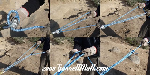
Step 1: Flip the thimble through the screw pin d-shackle making a loop.
Step 2: Pull loop back with your right hand, leaving the single cable in your left hand.
Step 3: Cross line in left hand through the loop, and switch the old loop to your right hand, and the single cable to your left hand.
Step 4: Pull on the single cable with your right hand to create a new loop. The single cable is now in your left hand again. Repeat this action to shorten the winchline as necessary.
Step 5: When the winch line is at the appropriate length, stick a bunch through the loop in your right hand and pull back with your left hand to close the loop. I use a hitch pin as a bung, but most anything solid will work. I have even used a rolled up newspaper before.
Step 6: Give the winchline a good tug, to make sure everything is good and tight. Now your ready to winch.
Here are some questions to ask yourself.
1) How far away is the nearest winchpoint where I wheel?
2) Will my winchline rub on anything?
For simplicity of this argument, lets focus on steel cable vs. synthetic.
Question #1 refers to the length of your cable. The wheeler who enjoys going through the Southern California Desert is going to need a much longer cable than someone who spends their time in Rousch Creek.
The goal is to have 5 wraps with steel cable, or 10 with synthetic when you start your pull. I round it up to 10' longer than your average pull. So lets say your from PA, and most of your pulls are 20-40' long. I would tell you to run a 50' winchline.
But if you are from Southern California, the anchor may be 100-200 feet away. So this person may need 150' of cable on the drum, plus a winch extension line (or 2).
But if you run synthetic line, you can easily shorten the winch-line to make sure you get those 10 wraps on the drum... more on that below.
Onto question #2. will my winchline rub on anything?
If you answered yes to this question, do not run synthetic line. Tree branches, rocks, and other environmental factors can easily damage a synthetic line and cause it to snap very very easily.
Are the most abrasive conditions your winchline will see be sand? Or are you going to be extra careful with the winchline to make sure it never rubs a rock? Then synthetic will be a great choice.
Remember, having synthetic line is much safer than steel line. Synthetic line does not stretch line steel. Steel will stretch about 15%, and if it were to snap, it take out anything in its path. This is where I want to add a very cool photo of a winchline that went through a land rover discovery, but I can't fine the photo. I would love it if someone could post that photo up for me.
An interesting thing to think about, is a synthetic line is easily damaged by the outside environment, but is not damaged by itself. A steel cable is not easily damaged by the outside environment, but is easily damaged by itself. For example, when you spool a steel cable, it is easy to kink the line, putting in a stress point, and weakening it. Leave it like that for too long, and it can fail.
If synthetic line snaps, you will most likely get a bruise. Although the biggest advantage I see, is how much easier it is to run a synthetic cable up a hill.
To the average user, who is clueless about winches, manufacturers have found that 100' of steel cable is the best choice. It is abrasion resistant, and is a good length to attach to the nearest winch anchor. This is why almost every winch you see on the market today has around 100' of steel cable on it.
To the question about fire wire. All winchlines should be able to withstand some heat from the bare drum. Otherwise, the line can melt, and thus, fail. So if you have a planetary winch, make sure the wrap around the drum is some kind of high temperature line.
Here is a trick I learned from Bill Burke about shortening winch lines, and winch extension lines. Just make a daisy chain. It does not hurt the winchline, and gives you the ability to tailor the length of the line to fit your pull:
Step 1: Flip the thimble through the screw pin d-shackle making a loop.
Step 2: Pull loop back with your right hand, leaving the single cable in your left hand.
Step 3: Cross line in left hand through the loop, and switch the old loop to your right hand, and the single cable to your left hand.
Step 4: Pull on the single cable with your right hand to create a new loop. The single cable is now in your left hand again. Repeat this action to shorten the winchline as necessary.
Step 5: When the winch line is at the appropriate length, stick a bunch through the loop in your right hand and pull back with your left hand to close the loop. I use a hitch pin as a bung, but most anything solid will work. I have even used a rolled up newspaper before.
Step 6: Give the winchline a good tug, to make sure everything is good and tight. Now your ready to winch.
When you do a winch pull with the motor, the motor is taking the load. If you pull on the cable by moving the truck when the winch is off, then the brake is taking the load, which might not be good for it, especially when it gets shock loaded.
Pulling on the cable with the truck is a lot more likely to cause a shock load, and shock loads can be several times that of a normal winch pull. This could cause a failure somewhere (probably the cable). That's why yank straps are better for pulling with the vehicle- they stretch to absorb and reduce some of the shock load, and they have higher pull ratings. If you were in low-low and very careful not to yank and cause a shock load, I'm sure it would be ok though.
And don't combine a winch with a yank strap either. I did that dragging OOP's out of Fordyce once. When the cable (rope) broke, the yank strap shot his winch hook at my rig. Luckily it went under my rig instead of into it. Lesson learned! :eek: I should have known better though...
If you read Eriks he told you why not to use a tow strap, you want to use winch rope.
Here are a couple of threads by Scott at Rockstomper on spliceing and putting loops in winch rope.
http://www.pirate4x4.com/forum/showt...hreadid=177074
http://www.pirate4x4.com/forum/showt...hreadid=177344
Here are a couple of threads by Scott at Rockstomper on spliceing and putting loops in winch rope.
http://www.pirate4x4.com/forum/showt...hreadid=177074
http://www.pirate4x4.com/forum/showt...hreadid=177344
Someone gave me the link once to ones from autozone for $15 a piece. I tried to find them, with no luck.
Although, seriously consider wiring in a Superwinch S3 Solenoid, or another manufacturer's sealed solenoid box. The S3 is the solenoid which is in the EP series and husky series winches. I believe the T-Max Boomer box is the same kind of solenoid setup. If it is sealed, the contacts do not get corroded, thus, they have less resistance, and are less likely to fail. Plus, most of these newer sealed solenoids are designed as a 450 amp solenoid, instead of running 2 85 amp solenoids in parallel.

Your solenoid box, with a bad solenoid, and the control plug taken out is worth around $50. It goes back to everything with Warn stamped on it being worth gold. The S3 solenoid is $120. So your out $70, but have a FAR more reliable solenoid setup.
Although, seriously consider wiring in a Superwinch S3 Solenoid, or another manufacturer's sealed solenoid box. The S3 is the solenoid which is in the EP series and husky series winches. I believe the T-Max Boomer box is the same kind of solenoid setup. If it is sealed, the contacts do not get corroded, thus, they have less resistance, and are less likely to fail. Plus, most of these newer sealed solenoids are designed as a 450 amp solenoid, instead of running 2 85 amp solenoids in parallel.
Your solenoid box, with a bad solenoid, and the control plug taken out is worth around $50. It goes back to everything with Warn stamped on it being worth gold. The S3 solenoid is $120. So your out $70, but have a FAR more reliable solenoid setup.
Recovery 101 LINK
http://www.pirate4x4.com/tech/billav...ery/index.html
Winches From Hell Test Comparison: cheap Vs expensive winchs in real world situations
Last edited by dropzone; May 1, 2009 at 12:23 AM. Reason: added a link
Feb 16, 2009 | 08:28 PM
#7
Registered User
Joined: Aug 2007
Posts: 872
Likes: 1
From: Reno, NV
When I find good stuff, I print it so I have a copy.
But this makes it difficult to reproduce or keep digitally. I wish a forum thread could be cut and pasted onto a word doc. (I've tried unsuccessfully to do this, forums must do something different so you can't do this)
THanks, Phil
But this makes it difficult to reproduce or keep digitally. I wish a forum thread could be cut and pasted onto a word doc. (I've tried unsuccessfully to do this, forums must do something different so you can't do this)
THanks, Phil
Trending Topics
Feb 19, 2009 | 07:47 PM
#8
Gear Calculators
Here are a couple of gear calculators that you can you to figure real world rpm's with assorted gears and tire sizes:
http://www.4lo.com/calc/gearratio.htm
this one has a ton of optionss:
http://www.grimmjeeper.com/gears.html
http://www.4lo.com/calc/gearratio.htm
this one has a ton of optionss:
http://www.grimmjeeper.com/gears.html
Feb 19, 2009 | 08:42 PM
#9
Alternator upgrades/Electrical info
Toyota Electrical 101
good source for electrical stuff: http://order.waytekwire.com
Toyota High Output Alternator INfo http://www.ttora.com/forum/showthrea...eferrerid=8874
Wiring Chart (amps to gauge size)

Cool Aux Fuse box kit; http://dogbytecomputer.com/blue-sea-...ative-bus.html
1981 Toyota Truck Wiring Diagram
http://s119.photobucket.com/albums/o...ruck%20wiring/
1st Gen ('81) Vacuum Diagrams: http://s119.photobucket.com/albums/o...acuum%20lines/
22R(RE) alternator upgrades (borrowed from this thread http://pirate4x4.com/forum/showthread.php?t=587456)
GM alternator to 22RE conversion:
Basic Diagram for wiring Aux Light with a relay
Compliments of Elton:
click to enlarge, than when open, click again to enlarge one more time

good source for electrical stuff: http://order.waytekwire.com
Toyota High Output Alternator INfo http://www.ttora.com/forum/showthrea...eferrerid=8874
Wiring Chart (amps to gauge size)
Cool Aux Fuse box kit; http://dogbytecomputer.com/blue-sea-...ative-bus.html
1981 Toyota Truck Wiring Diagram
http://s119.photobucket.com/albums/o...ruck%20wiring/
1st Gen ('81) Vacuum Diagrams: http://s119.photobucket.com/albums/o...acuum%20lines/
22R(RE) alternator upgrades (borrowed from this thread http://pirate4x4.com/forum/showthread.php?t=587456)
I did this mod on my 82 Pick-up and it works great!
The early 22R's pre 84.5's run the 40 Amp externally regulated alternators.
While the 85+ 22R's have the 60 Amp internally regulated alternators.
Comparison photo, the early model alt is considerably larger.

The lower engine/alternator mounts are different, sorry I don't have pics of them. But the older 40amp alternator is mounted in a "female" fashion, while the older mounted in a "male" fashion. The upper mount/adjustment point are the same on both alternators/engines.
The wiring harness from the alternators to the fenderwell plugs are also different. They both are wired differently and have different plug patterns. The only mod necessary is on the fenderwell wiring:
-Carefully remove the 'cover' on the top of the plug(no pic again!)
-Pry the wires out the back of the plug

-Eliminate the external regulator with wiring, LEAVE enough wire to splice into the alternator connection.

-Simple color coordination here, just line up the colors with the coresponding color on the "new" alternator harness. yellow-yellow red-red black-black white-white
-You will have a extra yellow wire after you splice the new connector, I just spliced it into the other yellow wire. PIC

I just ran a 8Ga wire from the white to my ammeter with a 60 amp inline fuse to the battery.
Parts needed for swap:
-Motor/Alternator mount from later 85+ 22R with internally regulated alternator
-Alternator wire harness from alternator to fenderwell plug
-Internally regulated alternator
The early 22R's pre 84.5's run the 40 Amp externally regulated alternators.
While the 85+ 22R's have the 60 Amp internally regulated alternators.
Comparison photo, the early model alt is considerably larger.
The lower engine/alternator mounts are different, sorry I don't have pics of them. But the older 40amp alternator is mounted in a "female" fashion, while the older mounted in a "male" fashion. The upper mount/adjustment point are the same on both alternators/engines.
The wiring harness from the alternators to the fenderwell plugs are also different. They both are wired differently and have different plug patterns. The only mod necessary is on the fenderwell wiring:
-Carefully remove the 'cover' on the top of the plug(no pic again!)
-Pry the wires out the back of the plug
-Eliminate the external regulator with wiring, LEAVE enough wire to splice into the alternator connection.
-Simple color coordination here, just line up the colors with the coresponding color on the "new" alternator harness. yellow-yellow red-red black-black white-white
-You will have a extra yellow wire after you splice the new connector, I just spliced it into the other yellow wire. PIC
I just ran a 8Ga wire from the white to my ammeter with a 60 amp inline fuse to the battery.
Parts needed for swap:
-Motor/Alternator mount from later 85+ 22R with internally regulated alternator
-Alternator wire harness from alternator to fenderwell plug
-Internally regulated alternator
90 supra runs a 80 amp alternator and it is a plug and play.
Yep. The late 80's Corolla, Supra, Cressida and Mini trucks all ran the same physical size Alternator. The Supra and Cressida got 80 ampers and the rest got 60 amp.
Might have to swap the pully but that would be it. Somethign weird is the early 90's 4Runner got a 70 amp on the 22RE's and it has a different plug.
ended up going with a gm type 140 amp powermaster... and one of aaron's skookum bolt on passenger side GM alt brackets:
aaron518@charter.net
The alternator is one wire capable - I wired it up 3 wire for better performance. Review the mad electric link for more info:
http://www.madelectrical.com/electri...hreewire.shtml
Good Links:
aaron518@charter.net
The alternator is one wire capable - I wired it up 3 wire for better performance. Review the mad electric link for more info:
http://www.madelectrical.com/electri...hreewire.shtml
Good Links:
22RE Alternator Upgrades / Tech useful links:
http://www.4x4wire.com/toyota/tech/alternator/
http://mralternator.com/alternators/toyota.html
http://www.4crawler.com/4x4/CheapTri...er/index.shtml
11-22 added the following:
http://www.off-road.com/toyota/tech/100alt/
ORC writeup on adding GM alternator to Toyota V6
http://www.madelectrical.com/electri...elcoremy.shtml
Good writeup on the GM 10si and 12si alternators.
http://www.densoaftermarket.com/prod...121&aaia=25688
Good pic of the stock Denso alternator
http://www.premierpowerwelder.com/specs/PP155.html Geezey peezey this one has got the bling factor all to hell - $900!?!
http://www.mobi-arc.com/pricing.htm (Go all the way to near the bottom). Note the Powermaster reference, but no pricing information.
http://www.powermastermotorsports.com/toyota.html
another high-priced alternative
more good sites:
http://www.home.earthlink.net/~twopapa/bigalt.htm
http://www.csupomona.edu/~cdcabrera/gm1wire.htm
http://www.pirate4x4.com/forum/showthread.php?t=47624
This appears to be the best writeup available:
http://www.rocketcityrockcrawlers.co...lt_upgrade.htm
Compliments of Elton:
click to enlarge, than when open, click again to enlarge one more time

Last edited by dropzone; Apr 26, 2009 at 12:42 AM. Reason: found some alternator stuff
Feb 19, 2009 | 08:56 PM
#10
Registered User
Joined: Jan 2009
Posts: 982
Likes: 1
From: Tacoma, Washington
what does the extra fluid capacity give you?
Feb 28, 2009 | 12:36 AM
#11
Brake Master Cylinder/Booster Upgrades
somethings I have been reading about the 1" MC (I have one to install too) is that the brakes will feel worse after the swap because the ratio is different unless you convert to a dual diaphram master cylinder (86-87 turbo truck or 88 V-6 4runner, T100's or something like that)
with the stock first gen booster and 1" MC the pedal may feel like it is stiffer and go closer to the floor. here is the MC thread I was reading:
http://www.pirate4x4.com/forum/showthread.php?t=763888
booster links:
http://home.4x4wire.com/erik/4runner/brakes/
http://www.pirate4x4.com/forum/showt...ferrerid=89727
Load Sensing Proportional Valve: LSPV --more to follow
Removal: http://4x4spot.com/proportioning.htm
http://www.off-road.com/trucks4x4/ar....jsp?id=186295
Rebuilding Brake Calipers (good detailed writeup)
http://www.pirate4x4.com/forum/showthread.php?t=770289
Turbo/Dual Diaprahm Brake Booster Upgrade
with the stock first gen booster and 1" MC the pedal may feel like it is stiffer and go closer to the floor. here is the MC thread I was reading:
http://www.pirate4x4.com/forum/showthread.php?t=763888
Sounds like you have the opposite problem I have.
I swapped in the bigger Calipers and now the pedal is too soft and goes to the floor.
Basically, your Master Cyl is too big for the stock 85 calipers. Just replacing one part of the brake system does not always make the brakes better. You have to keep the 'system' working together. Too hard of a pedal means the master is too big. Too soft means it is too small.
Here is the general rundown of how it should be setup.
13/16" master with 4 cyl (2 small/2 large piston) calipers and 79-85 drum brakes
7/8" master with 4 cyl (2 small/2 large piston) calipers and 86-95 drum brakes
1" master with 6 cyl (4 large piston) calipers and 86-95 drum brakes.
Look on the bright side. The 13/16" master cyl is $29 at autozone.
To expand on that some more:
The 13/16" master with small early calipers have a master/caliper hydraulic ratio of 7:1.
Swapping to a 1" master with the small calipers reduces that to 4.6:1.
The pedal will feel much harder, but you lose about 35% of the braking power you had before.
The later trucks with a 1" master and big calipers have a 5.7 ratio, but they made up for that with a dual diaphragm booster.
More info here:
http://home.4x4wire.com/erik/4runner/brakes/#Basics
None of the places selling "big bore masters" bother to explain any of this to you though. :p
http://home.4x4wire.com/erik/4runner/brakes/
http://www.pirate4x4.com/forum/showt...ferrerid=89727
Load Sensing Proportional Valve: LSPV --more to follow
Removal: http://4x4spot.com/proportioning.htm
http://www.off-road.com/trucks4x4/ar....jsp?id=186295
Rebuilding Brake Calipers (good detailed writeup)
http://www.pirate4x4.com/forum/showthread.php?t=770289
Turbo/Dual Diaprahm Brake Booster Upgrade
The brake booster on 1st gen Trucks is pretty dang small and the brakes suck to begin with and throw bigger tires on there you are stressing a system designs for 225/75/15's. I saw this thread over on Pirate and thought that I would pass it on, relatively cheap and easy upgrade.. Thanks to drsmash for finding a great way to improve some brake systems that are getting old and tired
I will be doing this one soon...
http://pirate4x4.com/forum/showthread.php?t=689905
part # at napa: both 2 and 4 wheel 532460
the newer booster is a dual diaphram so it should improve braking dramatically.
Pictures are from original thread:
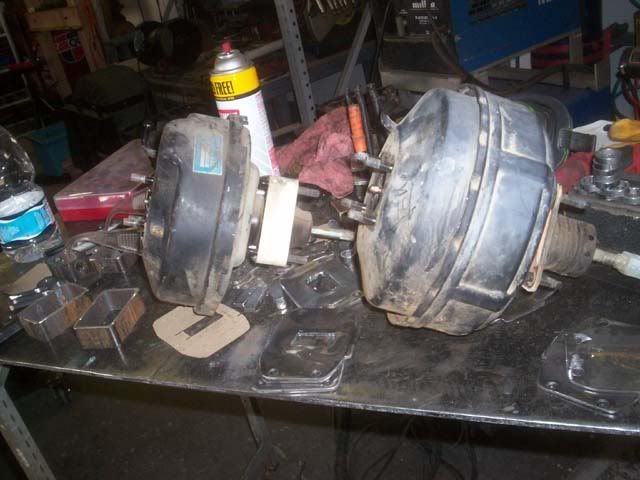
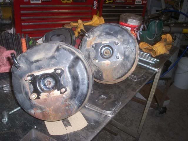
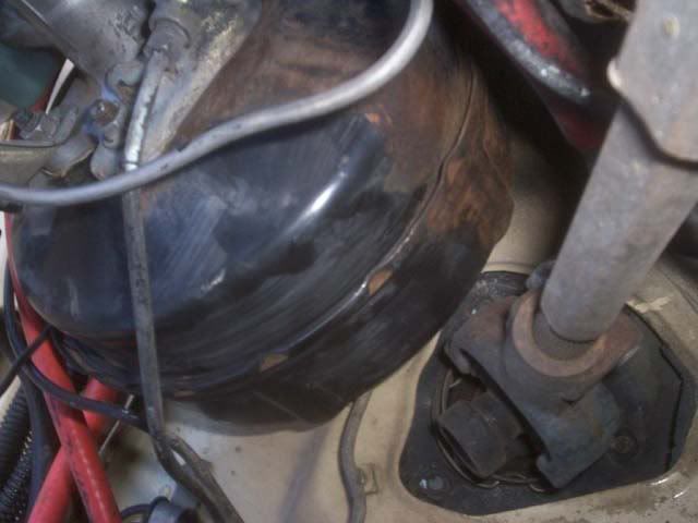
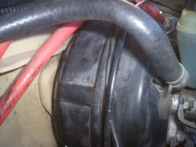
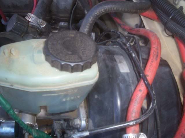
I will be doing this one soon...
http://pirate4x4.com/forum/showthread.php?t=689905
part # at napa: both 2 and 4 wheel 532460
the newer booster is a dual diaphram so it should improve braking dramatically.
Pictures are from original thread:
Last edited by dropzone; May 22, 2009 at 06:05 PM.
Feb 28, 2009 | 12:40 AM
#12
Mar 5, 2009 | 08:55 PM
#13
1st gen cab on 2nd Gen Frame
Putting a 1st Gen Cab on a 2nd Gen Frame:borrowed this from Pirate:
New info. I'm close to putting my 79 cab on my 88 frame. Threw this together this afternoon.
The 84 and 85 front cross member is 1.46 inches higher than the middle of the frame; The 86-95 front xmember is flush with the middle
1st gen Cab mount width eye to eye
2nd gen Width eye to eye
1st gen Length, eye to eye
Width Difference between 1st and 2nd gen
Relocating body mounts to fit 1st gen cab on 2nd gen frame
The 84 and 85 front cross member is 1.46 inches higher than the middle of the frame; The 86-95 front xmember is flush with the middle
1st gen Cab mount width eye to eye
- Front 31.5 inches
- Middle 47.16 inches
- Rear 47.56 inches
2nd gen Width eye to eye
- Front 33.07 inches
- mid 46.3 inches
- rear 46.3 inches
1st gen Length, eye to eye
- Between 1st and 2nd body mount, 44.61 inches
- Between 2nd and 3rd body mount, 38.5 inches
- Overall length of cab mount front to rear, 83.11 inches total
- Between 1st and 2nd body mount, 43.98 inches
- Between 2nd and 3rd body mount, 43.78 inches
- Overall length of cab mount front to rear, 87.76 inches total
Width Difference between 1st and 2nd gen
Relocating body mounts to fit 1st gen cab on 2nd gen frame
- Move Front Cab mount .785 inches inward on each side.
- Middle cab mounts will have to be moved .515 inches outward on both sides and .63 inches back on each side.
- Rear cab mounts will have to be moved 4.65 inches forward, and .63 inches outward.
Mar 6, 2009 | 05:38 PM
#15
Putting Bigger Japanese Engines in Toyota Trucks
New website for putting Bigger Japanese engines in Toyota Trucks:
UZSWAP.com
UZSWAP.com
Mar 8, 2009 | 09:21 AM
#16
1st Gen Truck Build Links
If you see a killer first Gen Truck build (2wd or 4WD) Send me a PM with the Link and I will add it here:
One of my Favorites:
MT-Toy's '82
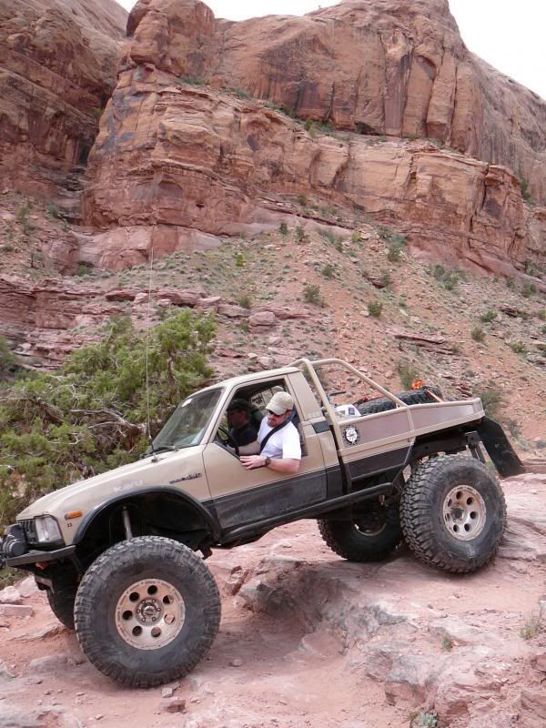
Nitteberg's 1st Gen on Volvo Portal Axles

Sweet 1st Gen Double Cab from Australia
I want this truck!!!
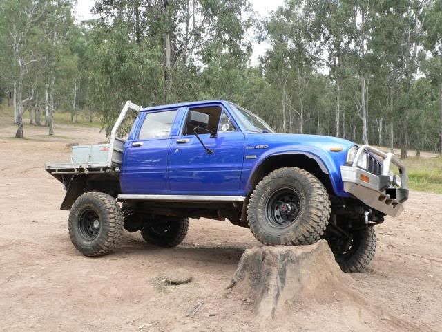
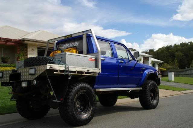
One of my Favorites:
MT-Toy's '82
Nitteberg's 1st Gen on Volvo Portal Axles
Sweet 1st Gen Double Cab from Australia
I want this truck!!!
Last edited by dropzone; Feb 10, 2011 at 12:03 PM.
Mar 8, 2009 | 09:34 AM
#17
Engine Info
22R Carb Trouble Shooting
http://www.bluebassdesign.com/boonin/carb_faq/
Converting 22R to 22RE info:
http://www.pirate4x4.com/forum/showt...ferrerid=89727
Pre '83 EFI Conversion Link
22RE.com
engine builder: http://www.engnbldr.com/
22R(RE) Oil Pans:
22RE-Propane & Turbo
22R(e) Propane Conversion kits: http://www.gotpropane.com/
ebay Kits: http://stores.ebay.com/Nash-Lift-Truck
http://pirate4x4.com/forum/showthrea...=turbo+propane
http://pirate4x4.com/forum/showthrea...=turbo+propane
http://www.blackflag4x4.com/Unclejesse.htm
http://pirate4x4.com/forum/showthrea...=turbo+propane
http://pirate4x4.com/forum/showthrea...=turbo+propane
22RTE (turbo)
http://www.22rte-trucks.com/simplema...orum/index.php
Supra 6 cyl mods: (from this thread on Pirate)
http://www.bluebassdesign.com/boonin/carb_faq/
Converting 22R to 22RE info:
http://www.pirate4x4.com/forum/showt...ferrerid=89727
Pre '83 EFI Conversion Link
22RE.com
engine builder: http://www.engnbldr.com/
22R(RE) Oil Pans:
22R(e) Propane Conversion kits: http://www.gotpropane.com/
ebay Kits: http://stores.ebay.com/Nash-Lift-Truck
http://pirate4x4.com/forum/showthrea...=turbo+propane
http://pirate4x4.com/forum/showthrea...=turbo+propane
http://www.blackflag4x4.com/Unclejesse.htm
http://pirate4x4.com/forum/showthrea...=turbo+propane
http://pirate4x4.com/forum/showthrea...=turbo+propane
22RTE (turbo)
http://www.22rte-trucks.com/simplema...orum/index.php
Supra 6 cyl mods: (from this thread on Pirate)
I put a 7m-ge in my 4runner so I thought I would start this for the FAQ... I will post what I remember and what I can find. I you have done this swap and I a missing anything please chime in. Or if you have swapped a different supra engine post up any info you have.
7m-ge
Bell Housing/ transmission
There is no 4 wheel drive transmission that will directly bolt up to this engine, but with that said there are some options out there.
W and G series transmissions
A bell housing from a N/A supra manual transmission will bolt up to a W or G series 4 wheel drive transmission and the 7m and 5m blocks.
R series transmissions
There is no direct swap to make this work (that I know of). People have made their own custom bell housings, but this most likely requires machine work and or the capability to weld aluminum.
There is also this after market housing off of Supracharged website; I have no info on quality or compatibility
http://www.monster-performance.com/m...products_id=32
Motor Mounts
Mounts from the 5m-ge will allow a direct bolt into a 22 series engine bay
Oil Pan
The oil pan from the supra will allow more clearance over the oil pan from the Cressida
Wiring
***info from SupraCharged.com***
The C1 connector (yellow connector near igniter) has 2 wires that you will use if you use the EFI main relay in conjunction with the circuit opening relay. Wires that you may need from this connector:
Black/Orange - (M-REL on ECU, not required) - Used as the activating power to the EFI Main Relay
Black/Yellow - (BATT on ECU, required) - constant power, use a 7.5 amp FUSE
EFI Main Relay - In the Supra turbo and other Toyota Turbo vehicles, the ECU controls the EFI Main (M-REL off the ECU.) In Toyota non-turbo cars and trucks, the EFI Main is controled by the ignition switch. You don't have to change this, as I have not seen any problems running it this way, unless you are picky and want to have it exactly the same as the turbo configuration.
If you do want to run it like the 7MGTE, you will have to cut the relay coil power wire that goes into the EFI
main. The location of the EFI main will vary depending on the year of your vehicle. You will need connect the
M-REL wire from the C1 connector, and use it to power your factory EFI main. Again, this will be the Black/Orange wire at the C1 connector. The output of the EFI main should then supply the power to the Circuit Opening Relay.
The Circuit Opening Relay(COR) is what supplies power to the fuel pump. The power that is sent to the COR then to the fuel pump comes from the EFI Main Relay, so the EFI main must be activated before power can be supplied to the COR. The COR has a dual coil for activation, one of the relay coils can be activated by the starter. This is done by supplying power from the starter wire to the relay coil which has a constant ground. That wire is a small guage black wire with blue stripe coming from the large yellow connector (B1) by the ECU. Just tie this wire into your starter wire. The other coil is activated by the Fuel Control, or FC (B1 connector) from the ECU. The ECU sends a ground signal to the COR, and if relay has power from the EFI main relay(discussed earlier), then the COR will supply power to the fuel pump, or the Fuel Pump Control Relay if you wish to use it. If you are running a non-turbo engine, the COR is controled by the green wire going into the AFM, not the ECU. You can splice into that green wire and tie that into the green wire on your project vehicles AFM connector. That will take care of the pump problem.
Fuel Pump Control Relay(FPCR) - (Not Required)- Once power is able to pass through the COR, there is then a FPCR.
This is just a resister to change the voltage to the fuel pump. I have run many swap without this without any problems or any changes in gas mileage. This recieves power from the COR for both the contact switch, and the relay coil. The ground is controled by the FP (B1 connector) signal coming from the ECU.
Both the FPCR and COR are not needed to make this run properly, but you will need to find an alternate way to control the fuel pump. At first I just had mine connected to the ignition switch. Problem with that, is your fuel pump is always if your ignition is on(like if you get in a wreck, you pump will keep pumping fuel....not good).
Summary
In short, if all that was confusing, the only thing you really need to do on the C1 connector is hook the black/yellow wire to constant power. Then for the fuel pump control, hook the green wire up the the FC from the ECU. The 7MGE(non-turbo), does not have a FC from the ECU, instead you will splice the green wire into the 7M engine harness near the 7M AFM connector. I hope after all this, you aren't confused too much.
The B1 connector, or "THE BIG YELLOW CONNECTOR, near the ECU" There are 5 wires you will use grom this connector:
BLACK/WHITE - Large 10 guage Black with a white stripe - Starter (depending on year, AT/MT, this could have a white or blue stripe)
Black/orange - Large 10 or 12 guage black with a orange stripe - Needs switched power. This runs directly from the ignition switch, and powers your injectors, coil, and igniter.
Black/orange - Small 16 guage black with orange stripe. This also needs switched power. This could be tied into the Large black/orage wire.
Green - (FC on ECU) - Green wire - This controls ground the Circuit Opening Relay
yellow - (FP on ECU) - Yellow wire - NOT NEEDED! this is used to reduce the voltage on the fuel pump, but is not
neccesary.
Starter
This is the wire that goes to the starter solenoid. It is located in the center part of the connector. In a
manual, this will travel from the ignition switch, through the clutch switch, through the starter relay, then
through this connector. Automatics are a little more difficult. If you do have an auto wiring harness, the starter wire run through the engine harness, to the tranny harness under the intake manifold. You will need to cut and splice the wires togother in order to complete the loop to feed power to the starter solenoid. The auto will usually use a Black/White wire, and the manual will use a Black/Blue wire. In some vehicles such as the 85-older supra's, and I have noticed older model pickups, that this wire goes through tho body harness. If this is the case, you will have to figure out where that is, splice into it, and run it to this connector. On newer vehicles the starter will run through the engine harness.
Accessory Power
This is a large black wire with an orange stripe. Along with the starter, these are the two center wires in this
connector. You have to have switched power to this wire in order to supply power to your injectors, coil, and igniter. This usually comes through the ignition, and requires at least 15 amps. In other words, don't use the
power from your radio.
Circuit Opening Relay(Ground)
The green wire coming from the FC signal from the ECU, controls the ground on the Circuit Opening Relay. As long as there is power to this relay(which is discussed on the C1 connector), power will then travel to the fuel pump, or Fuel Pump Control Relay. This allows your fuel pump only to turn on when the engine is running. When the engine stops running, the ECU will cut the ground signal to this wire, which will turn off the Circuit Opening Relay, and no longer supply power to the fuel pump.
Fuel Pump Control Relay(Ground)- This is for the resister, and is not needed This yellow wire from the FP signal on the ECU, is used for a dual speed fuel pump setting. The ECU will supply a ground to the Fuel Pump Control Relay, which will then change the resistance on the power going to the fuel pump.
The relay and resistor is located on the passenger side strut tower. I have run many swaps without this component, and have not seen any impact on fuel economy or peformance.
The M1 connector or "Small Yellow Connector" There are 5 wires you need from this connector:
Yellow/Black - yellow with a black stripe - oil pressure for guage and ECU
Yellow/Green - Yellow with a green stripe - Water temp for guage
Pink - Pink Wire - speed sensor from Combonation Meter.
Green/Gray - Green with gray stripe - Engine light black - Tach (tach mod may be required) Click here for details for 3VZE-7MGTE mod.
Water Temp
The water temp wire, yellow with black stripe is used for your guage only. This is not the temp sensor used for your ECU, so if you get a water temp error on your codes, this is not where you want to look to solve your problem. All toyota vehicles use this color wire for the temp guage, so your swap vehicle will have the same color wire.
Oil Pressure
The same is also true with the Oil Pressure wire. This comes from the oil pressure sending unit and will always
be the same color. Yellow with black stripe. On the 7M, this also feeds into the ECU. I am not really sure why
the ECU needs to know the oil pressure, as I have found it to have no impact on the way the engine runs whether or not it is hooked up to the ECU. In fact, your guage might not even work if it runs through the ECU. You also may need to use your Oil sending unit from your old motor. They are calibrated for the guage on your vehicle. These are pretty easy to change with a 14mm open end wrench, or a very large socket.
Engine Light
The Engine light requires a ground signal from the ECU. This is a black wire. Simple as that. Check your vehicles wiring diagram to figure out what what that is. The 7M uses the black wire, but on other vehicles, I have seen any different colors used. With the engine light, you can run your diagnostic codes, or engine codes by connecting TE and E1 in your "Check Connector" near the igniter. When you turn your ignition on, your light will flash codes. Here is a link for your Diagnostic Codes
Speed Sensor
The Speed Sensor wire, green with gray strip, comes from the Spedometer from your instrument cluster. This is how the ECU knows how fast your are going. I have noted, that connecting this wire will help with stalling. The wire etween the M1 connector and the ECU is pink, but the wire between the M1 connector and the Spedometer could be a range of colors. Refer to your vehicles electrical schematic to figure this out(EFI ONLY).
Tachometer
The Tach wire, black wire, does NOT come from the ECU, and it does NOT go to the ECU. A signal wire goes directly
from the igniter to your tach guage. You can also test this signal from the IG- terminal in the "Check Connector" near the igniter. And again, here is a link for the 3VZE tach mod.
Last edited by dropzone; Apr 3, 2009 at 08:22 PM. Reason: more info
Mar 8, 2009 | 09:45 AM
#18
Parts Sources
Parts/Bumpers/Mounts
4Crawler Off Road: http://4crawler.com/4x4/ForSale/ProductLine.shtml Custom body lifts, Driveshaft spacers, electrical solutions
Addicted Off Road: http://addictedoffroad.com/
TRD PARTS 4 U: http://trdparts4u.com/
4xinnovations: http://4xinnovations.com/
Marlin Crawler: http://marlincrawler.com/
trail-gear: http://www.trail-gear.com/
All Pro Off Road: http://www.allprooffroad.com/
Downey Off Road: http://www.downeyoff-road.com/ now out of business
Dave' Off Road Performance: http://www.davezoffroadperformance.com/ Tube doors, third members, driveshafts,etc
Toyota Truck Dismantlers: body parts/axles etc
The Toy Man (newberg, OR) http://www.thetoyotaman.com/
MazToy (troutdale, OR)http://maztoy.com/
Davez Off Road: http://www.davezoffroadperformance.com/
Yotayard (colorado) http://www.yotayard.com/home.htm
Jim's Got Parts (Denver, CO) http://jimsgotparts.com/
California Mini Trucks (Cali) http://www.calminitruck.com/
NIX99 (washington state) http://nix99.com/
Rancho Toyota Truck Dismantler (Cali) http://www.ranchotoyotatruckparts.com/
toy truckc (CA) http://www.toytruckscalifornia.com/
Toy Connection (CA) http://www.toyconnection4x4.com/home.html
All Toyota Truck and SUV (CA) http://www.alltoyotatrucksuvparts.com/
ToyoKings (FLA) http://www.toyokingsusedparts.com/
Yotatech Classifields :https://www.yotatech.com/forums/f91/
TTORA Classifieds: http://ttora.com/forum/forumdisplay.php?f=3
Pirate classifieds: http://pirate4x4.com/forum/forumdisplay.php?f=4
Parts Locators: http://www.autopartslocator.com/
http://www.seekautoparts.com/
Thread on http://www.toyotadiesel.com/forums/showthread.php?t=343 with Parts sources/ links in Cananda & Australia
Sticker Kits
Jame Dean Creations: http://jamesdeancreations.com/ Toyota vehicle sticker reproductions
Last edited by dropzone; Jan 5, 2015 at 04:39 PM. Reason: removed a bad vendor
Mar 15, 2009 | 01:09 AM
#19
SUspension
63" Chevy rear spring Conversion FAQ
Toyota Rears Up Front (RUF) FAQ
Front Spring Hanger Placement: (when using longer than stock springs like Trail Gears)
some of the following info is from this spring FAQ
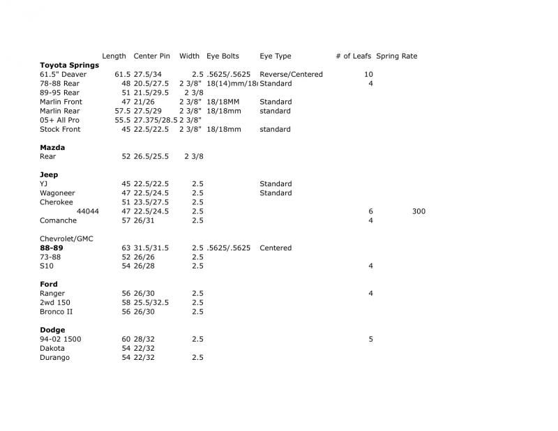
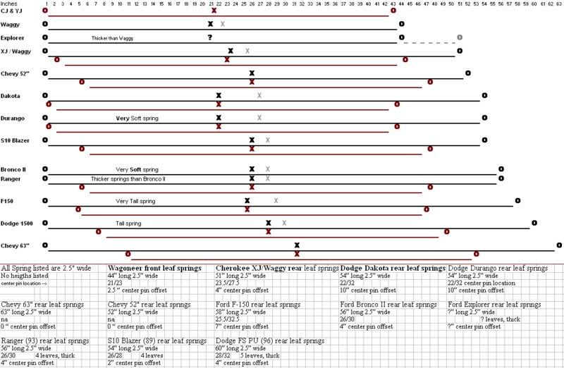
Spring Definitions
explained: --Link also has a spring rate calculator that is pretty cool
**Awesome Link for Spring Info: **http://littlekeylime.com/MrN/mrnimages/leaf_springs.png
Toyota Rears Up Front (RUF) FAQ
Front Spring Hanger Placement: (when using longer than stock springs like Trail Gears)
He can't with the 3" springs. In fact, he needs to mount it 1/4" back of the front crossmember for a decent shackle angle and to have the tie rod and draglink clear each other on compression. Otherwise he'll be having to move the steering box forward.
I have all of these lifts down to a science at this point.
3" springs: 1/4" in back of the frame. Push the frame tube jig all the way forward in the body mount.
4" Springs 1/2" in front. Center the frame tube jib in the body mount
5" springs 3/4" in front. Center the frame tube jib in the body mount
As someone who is always building 4wd vehicles, its nice to know leaf spring dimensions, to see what will and will not work in certain projects.
I'm trying to compile as much leaf spring information as possible. Please post up any specifications you may know. Right now the best website out there for this information is DRM's side: 4x4spot.com
79-88 Toyota 4wd Rear 20.5/27.5 long 2 3/8" wide 18mm/18mm or 14mm/18mm spring eyes.
88-98 Chevrolet/GMC 1500 31.5/31.5 long 2 1/2" wide .5625/.5625 spring eyes. Centered eyes.
61.5" Deaver Rear Springs 27.5/34" long 2 1/2" wide .5625/.5625 or .75/.75 spring eyes. Front reverse eye, rear centered eye.
Marlin/Trail Gear/All Pro front springs: 21/26" 2 3/8" wide 18mm/18mm bolt size.
Marlin/Trail Gear/All Pro Rear Springs: 27.5/29" 2 3/8" wide 18mm/18mm bolt size
All Pro 05+ 1.5" rear springs 55 1/2 OAL , 27 3/8 Pin to Front , 28 1/2 pin to rear .
Wrangler YJ: 22.5/22.5 2 1/2" wide
Stock Toyota Front: 22.5/22.5 2/ 3/8" wide 18mm/18mm bolt size
Spring Definitions
explained: --Link also has a spring rate calculator that is pretty cool
**Awesome Link for Spring Info: **http://littlekeylime.com/MrN/mrnimages/leaf_springs.png
Last edited by dropzone; Dec 9, 2011 at 12:12 AM. Reason: found some cool info
Mar 17, 2009 | 07:47 AM
#20
Upper transmission bolt access mod