22R Desmog Tutorial
 Apr 2, 2014 | 05:51 PM
#202
Thread Starter
Super Moderator
iTrader: (3)
Joined: Jan 2012
Posts: 3,218
Likes: 26
From: Salisbury, MD
You can do either, the plate on the bottom of the intake basically eliminates the Cold Mixture Heater (CMH) which helps on cold starts. Mine never worked to begin with and I never had starting problems
Apr 6, 2014 | 09:37 AM
#205

Registered User
Joined: Jun 2012
Posts: 109
Likes: 1
I've got most everything pulled off and I have a couple if questions. In regards to the piece/plate on the back I the head, what is actually behind that plate? Mine is just the raised plate bolted on there with nothing attached. My question is what is the need of pulling that off and putting the block off? What if I leave it as it is?
As for the heater and the rear of the timing cover. The drivers side looks to already be blocked. I see the other line that comes off and is to be blocked. So the water pump will push fluid through the intake and I can use the new bottom plate with barbed fitting? Is this adequate?
Finally, in regards to the charcoal canisters. How many of you got rid of them? I will begin the reassembly tomorrow when the LCE kit arrives.
Thanks
Last edited by mtrdud; Apr 6, 2014 at 09:41 AM.
Apr 6, 2014 | 09:44 AM
#206

Registered User
Joined: May 2013
Posts: 175
Likes: 0
The egr on the back of the head has channels for the exhaust gasses to be recirculates through the engine. You need to take it off and out the block plate on. Not sure for the heater. I called lce and figured out my setup with one of the techs(John). I removed both charcoal canisters. I have a couple feet of fuel line(curled into 3 loops and then a fuel filter on the end to vent my tank) on the line that would be the overflow/ vent line from the tank.
Apr 6, 2014 | 06:46 PM
#207
Registered User
Joined: Jun 2012
Posts: 109
Likes: 1
As far as the charcoal canisters. What serves as the vent line after they are removed? Taco, I understand what you are describing. Did you run that hose to the fender under the hood or where? Kawa what did you use ?
Last edited by mtrdud; Apr 7, 2014 at 02:58 AM.
Apr 7, 2014 | 04:20 AM
#209
Thread Starter
Super Moderator
iTrader: (3)
Joined: Jan 2012
Posts: 3,218
Likes: 26
From: Salisbury, MD
The plate on the back of the head (EGR Crossover) isn't necessary, but in blocking it off you will reduce engine temperature and increase cooling efficiency since you won't have unnecessary exhaust gases running around the back of the head.
Charcoal canisters can go. I removed my well before I started my build and never had any issues. Just run your return line straight back to the tank - that will help with the negative pressure in the tank. You'll want to snag a vented gas cap to help relieve the negative pressure as well. You'll also have an extra line coming off the tank that you'll want to plug so you don't get debris in your tank.
I plumbed my heater to the bottom of the intake from LCE. There are several ways that you can do the heater, but I found this way to be the cleanest looking
Apr 7, 2014 | 04:31 AM
#210
Registered User
Joined: Jun 2012
Posts: 109
Likes: 1
Ok. So to clarify, which one did you run the return to? The one that goes down to the one that is with the sending unit or the one that is by itself on the top of the tank? Make sense ?? This will also answer which one I plug also.
Thanks
Thanks
Apr 7, 2014 | 05:41 AM
#211
Thread Starter
Super Moderator
iTrader: (3)
Joined: Jan 2012
Posts: 3,218
Likes: 26
From: Salisbury, MD
The only one that matters is the fuel supply to the pump - that's the only one that goes to the bottom of the tank. You'll know right away if you got that one wrong LOL. The return can get hooked up to either of the other two and plug the one you have left over.
May 2, 2014 | 02:19 AM
#212

Registered User
Joined: Apr 2014
Posts: 4
Likes: 0
whats going on so im pretty new to yotatech but i was changing my head gasket did my timing chain all that good stuff and came across your post and was like ahh sounds like a good idea while i was putting my motor back together. so i went on and blocked off everything went along to easy then my regulator came in and that bracket how exactly did u mount it to your manifold did u have to drill bigger holes to mount it? and did you use different bolts? because doesnt look like theres much clearance for much. im just wondering because i was gonna mount it to the fender but looks alott better and cleaner how u setup. and again.. good post lce should sponsor you haha
May 2, 2014 | 06:51 PM
#213
Thread Starter
Super Moderator
iTrader: (3)
Joined: Jan 2012
Posts: 3,218
Likes: 26
From: Salisbury, MD
I get a few kickbacks from LCE... For the fuel pressure regulator, I just mounted it to an existing hole on the manifold with whatever bolt threaded in there. I did have to grind down the head of the bolt slightly so that the regulator would fit in the bracket.
Jun 1, 2014 | 08:44 AM
#214

Registered User
Joined: Jun 2014
Posts: 9
Likes: 0
I'm in the process of grabbing all the parts and noticed that the gauge had a 1/8" male connection rather than the 1/4"; otherwise the parts list looks good. Thanks for the information, if I notice any other discrepancies I'll let you know. =D
Jun 12, 2014 | 09:45 AM
#216
Registered User
Joined: Jun 2014
Posts: 9
Likes: 0
The heater hose will run from the 90* barb fitting that comes with the intake manifold plate to the heater core inlet on the firewall and then from the heater core outlet on the firewall to the factory fitting that comes off of the hard coolant pipe (mounted to the motor mount) on the driverside towards the front of the motor.
The throttle linkage is factory. I just gave it a very extensive cleaning.
The throttle linkage is factory. I just gave it a very extensive cleaning.
Here are some photos I've found, none of which illustrate an fully blocked off motor with coolant hose.
If clarification of the question is needed I'll draw and take some more pictures later.


http://imgur.com/a/5oBHZ
Last edited by kawazx636; Jun 12, 2014 at 12:29 PM. Reason: Fixed picture links
Jun 12, 2014 | 12:22 PM
#217
Thread Starter
Super Moderator
iTrader: (3)
Joined: Jan 2012
Posts: 3,218
Likes: 26
From: Salisbury, MD
For one, the engine with the red block in those pictures in that link you posted is a 22RE - the setup is a little different there.
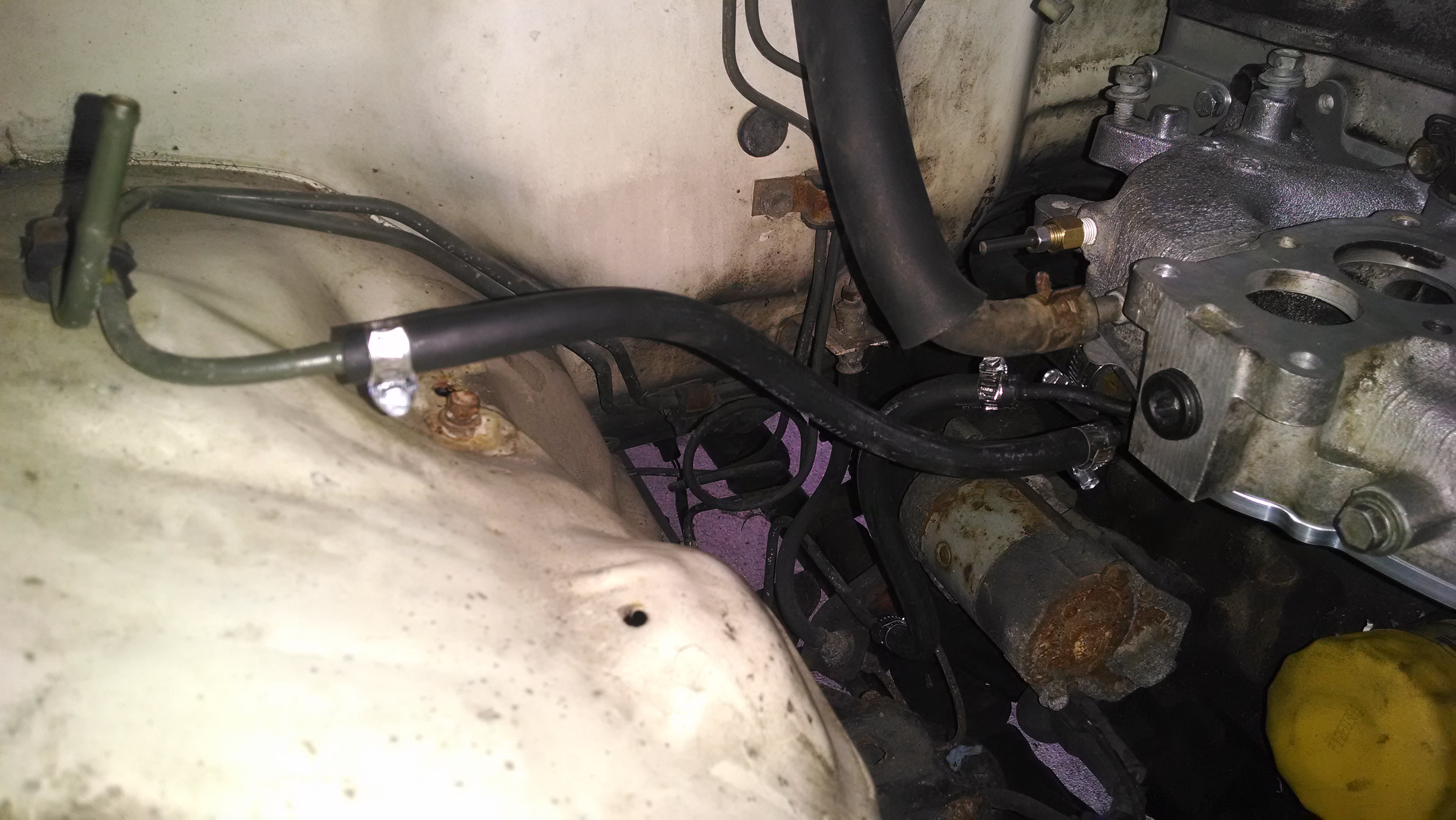
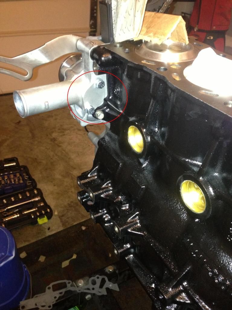
I've seen people route the return hose to the hard pipe on the back side of the driver side timing cover that I have blocked and circled in red here:

I don't know it that way works properly or not, but it seems like it would.
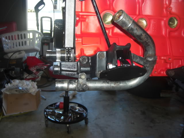
The way the return is ran from the factory there is a rubber hose that comes from the heater core to a metal pipe/bracket bolted on the driver side fender wall. There is a "hose holder" coming off the brake booster to hold the hose away from the exhaust:
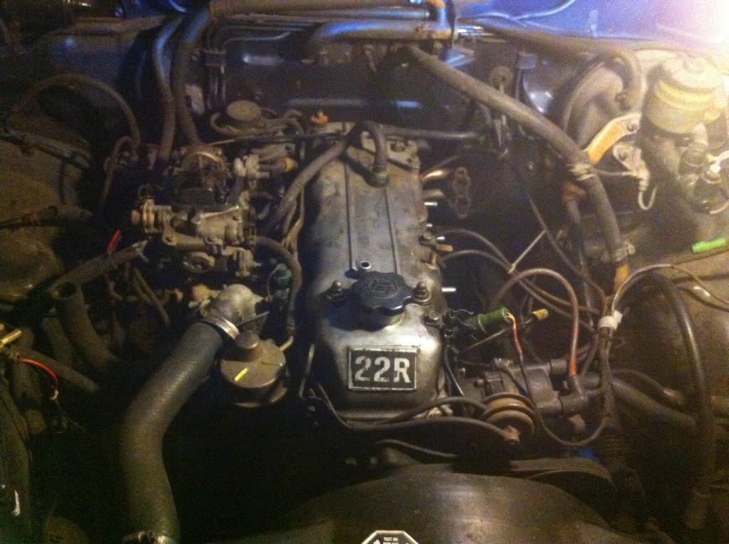
This is my engine before I started my restoration (Follow the bracket to the left of the brake reservoir to the hose and then down to the rusty pipe bracket on the fender wall):
This is another image I found online that is a little more clear and you can see the heat hose go all the way to the hard pipe down by the engine mount:

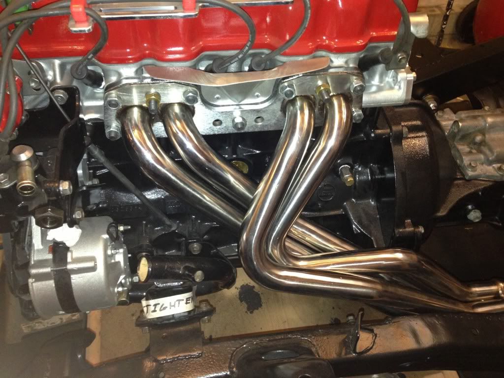
From the pipe/bracket on the fender wall, a rubber hose goes to the bung on the hard pipe (which has a coolant hose coming from the radiator on the lower end and a coolant hose going to the water pump on the upper end) down by the driver side engine mount to tie back into the coolant system.
Here are a couple shots of mine - You can see the bung that I am talking about right above the "E" on the piece of tape that I wrote "TIGHTEN" on to remind me to tighten the engine mounts down:
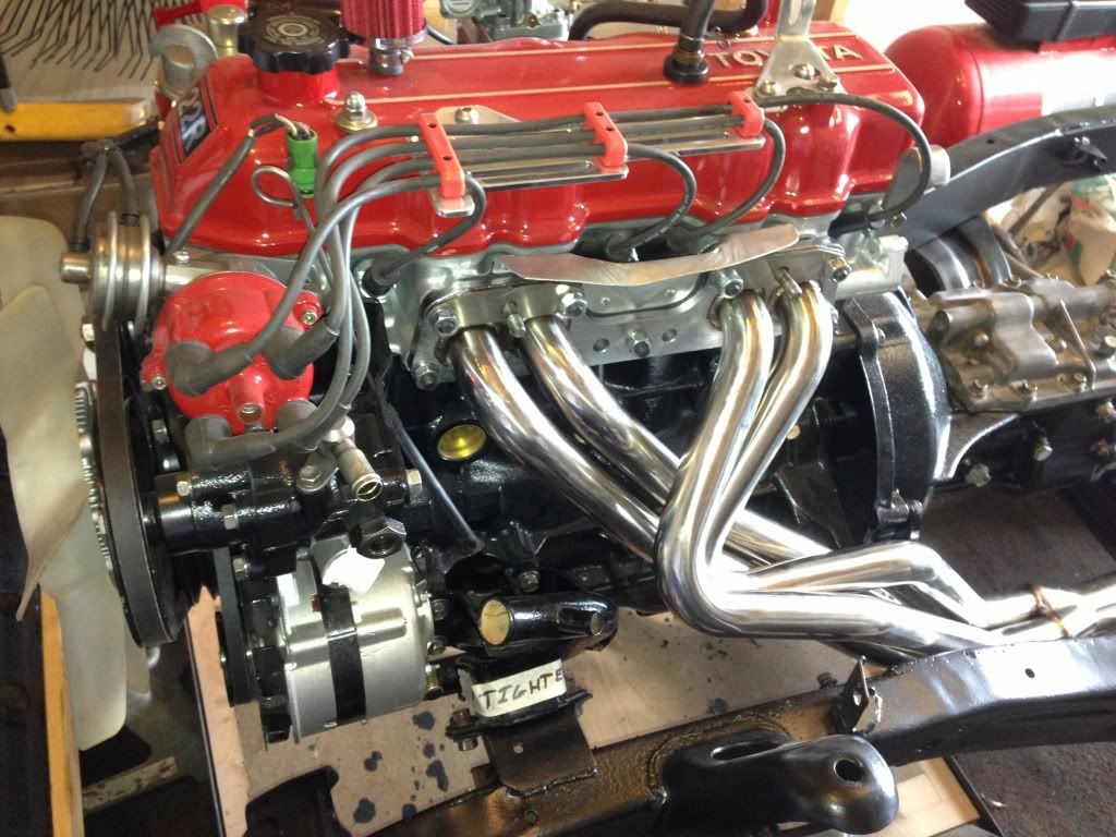

Did I clear it up for you or just make it more muddy??
I've seen people route the return hose to the hard pipe on the back side of the driver side timing cover that I have blocked and circled in red here:

I don't know it that way works properly or not, but it seems like it would.
The way the return is ran from the factory there is a rubber hose that comes from the heater core to a metal pipe/bracket bolted on the driver side fender wall. There is a "hose holder" coming off the brake booster to hold the hose away from the exhaust:
This is my engine before I started my restoration (Follow the bracket to the left of the brake reservoir to the hose and then down to the rusty pipe bracket on the fender wall):

This is another image I found online that is a little more clear and you can see the heat hose go all the way to the hard pipe down by the engine mount:
From the pipe/bracket on the fender wall, a rubber hose goes to the bung on the hard pipe (which has a coolant hose coming from the radiator on the lower end and a coolant hose going to the water pump on the upper end) down by the driver side engine mount to tie back into the coolant system.
Here are a couple shots of mine - You can see the bung that I am talking about right above the "E" on the piece of tape that I wrote "TIGHTEN" on to remind me to tighten the engine mounts down:


Did I clear it up for you or just make it more muddy??
Last edited by kawazx636; Jun 12, 2014 at 12:24 PM.
Jun 12, 2014 | 12:30 PM
#219
Registered User
Joined: Jun 2014
Posts: 9
Likes: 0
For one, the engine with the red block in those pictures in that link you posted is a 22RE - the setup is a little different there.
I've seen people route the return hose to the hard pipe on the back side of the driver side timing cover that I have blocked and circled in red here:
I don't know it that way works properly or not, but it seems like it would.
The way the return is ran from the factory there is a rubber hose that comes from the heater core to a metal pipe/bracket bolted on the driver side fender wall. There is a "hose holder" coming off the brake booster to hold the hose away from the exhaust:
This is my engine before I started my restoration (Follow the bracket to the left of the brake reservoir to the hose and then down to the rusty pipe bracket on the fender wall):

This is another image I found online that is a little more clear and you can see the heat hose go all the way to the hard pipe down by the engine mount:
From the pipe/bracket on the fender wall, a rubber hose goes to the bung on the hard pipe (which has a coolant hose coming from the radiator on the lower end and a coolant hose going to the water pump on the upper end) down by the driver side engine mount to tie back into the coolant system.
Here are a couple shots of mine - You can see the bung that I am talking about right above the "E" on the piece of tape that I wrote "TIGHTEN" on to remind me to tighten the engine mounts down:
Did I clear it up for you or just make it more muddy??
I've seen people route the return hose to the hard pipe on the back side of the driver side timing cover that I have blocked and circled in red here:
I don't know it that way works properly or not, but it seems like it would.
The way the return is ran from the factory there is a rubber hose that comes from the heater core to a metal pipe/bracket bolted on the driver side fender wall. There is a "hose holder" coming off the brake booster to hold the hose away from the exhaust:
This is my engine before I started my restoration (Follow the bracket to the left of the brake reservoir to the hose and then down to the rusty pipe bracket on the fender wall):
This is another image I found online that is a little more clear and you can see the heat hose go all the way to the hard pipe down by the engine mount:
From the pipe/bracket on the fender wall, a rubber hose goes to the bung on the hard pipe (which has a coolant hose coming from the radiator on the lower end and a coolant hose going to the water pump on the upper end) down by the driver side engine mount to tie back into the coolant system.
Here are a couple shots of mine - You can see the bung that I am talking about right above the "E" on the piece of tape that I wrote "TIGHTEN" on to remind me to tighten the engine mounts down:
Did I clear it up for you or just make it more muddy??
The pipe interconnecting between the heater side on the firewall, did you flip it to route back toward the manifold?
Jun 14, 2014 | 04:15 PM
#220
Registered User
Joined: Jun 2014
Posts: 9
Likes: 0
I am nearly done, I'm just mounting the carb and verifying fuel lines.
I plan on running without the charcoal canister, can I just block the vent line and replace the gas cap with a vented one?
Do these fuel lines look correct?

I plan on running without the charcoal canister, can I just block the vent line and replace the gas cap with a vented one?
Do these fuel lines look correct?