
RAD4Runner's 1986 4Runner dlx Build-up
 Apr 15, 2012 | 12:36 PM
#1
Thread Starter
Registered User


Joined: Mar 2012
Posts: 7,125
Likes: 681
RAD4Runner's 1986 4Runner dlx Build-up
Happy Spring, folks!
I feel fortunate to have found a pretty much stock, un-molested 1986 4Runner dlx, so this is not a build-UP in the strictest sense of the word. However, I would like to chronicle what I'm doing to it because some of the info may be useful for fellow members.
Stay Tuned...
I feel fortunate to have found a pretty much stock, un-molested 1986 4Runner dlx, so this is not a build-UP in the strictest sense of the word. However, I would like to chronicle what I'm doing to it because some of the info may be useful for fellow members.
Stay Tuned...
Last edited by RAD4Runner; Jun 23, 2017 at 09:45 PM.
Apr 15, 2012 | 12:51 PM
#2
Welcome to the site RAD. I like how you have your "Where Is " That will come in useful. Looking forward to your build. Stock and unmolested Urrgh.. I would like to find one like that.
Apr 15, 2012 | 09:22 PM
#3
Thread Starter
Registered User
Joined: Mar 2012
Posts: 7,125
Likes: 681
Light Reminder Mod
Thanks, Terrys87!
I'm concerned about leaving my lights on and draining the battery. Per FSM, the light reminder relay is supposed to be here, but I only see a mounting hole on mine, confirming my suspicion that the light reminder circuit was only available on SR5 first-gens. Therefore, one lazy afternoon, I got busy
The circuit is simple. It will energize when there is positive voltage from the tail light circuit AND ground via the the driver side door courtesy switch when door is opened. (When headlights are on, there is also power to tail light circuit.)
Parts & Equipment Needed: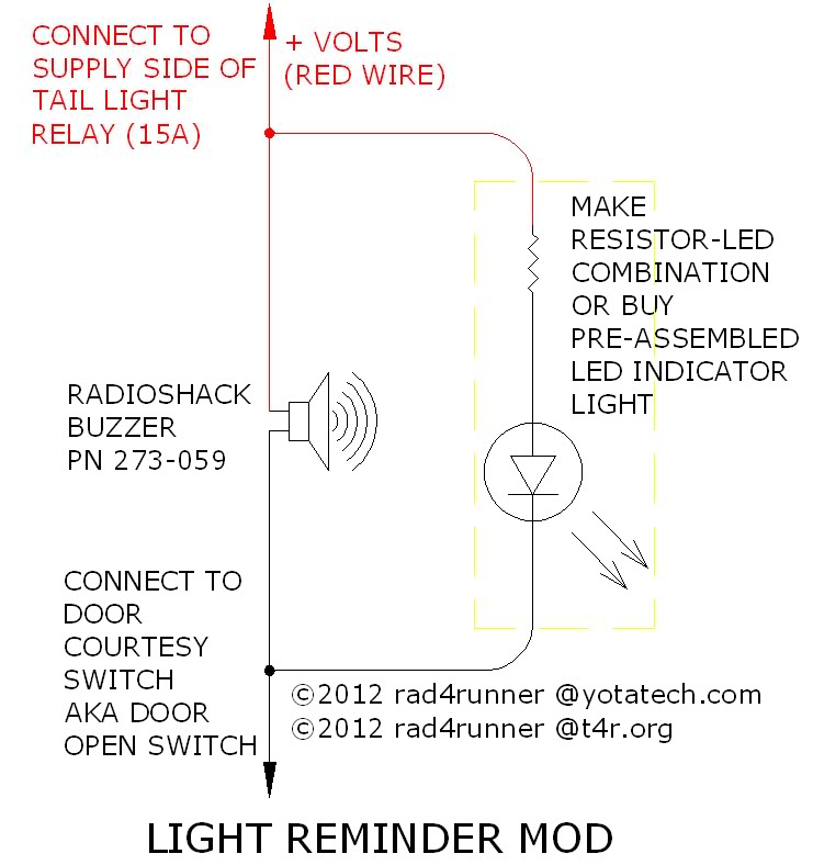
POSITIVE side will be tapped into tail light circuit between the tail light relay and the 15-amp tail fuse here: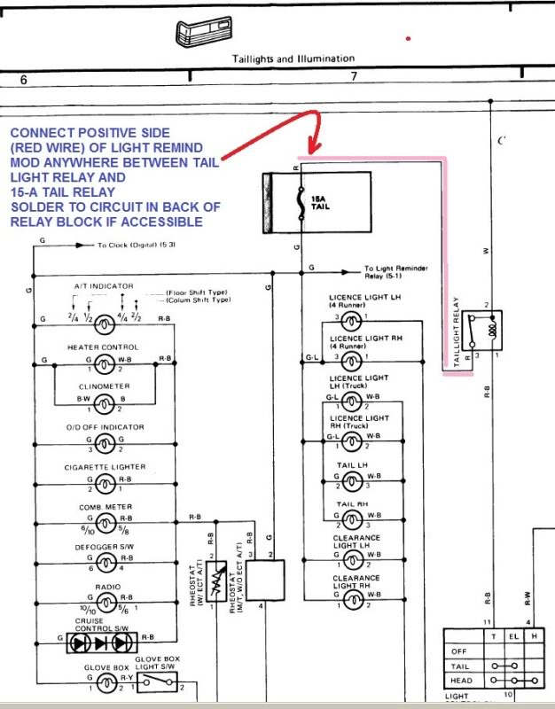
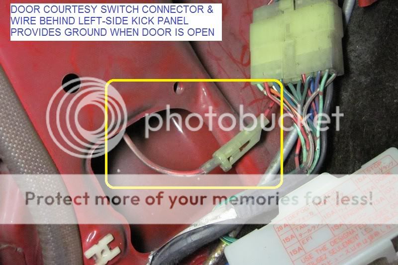
GROUND side will be connected to the door courtesy switch ( provides ground when door is opened) here: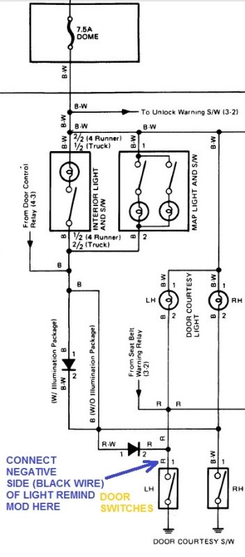
Assembled circuit is shown here: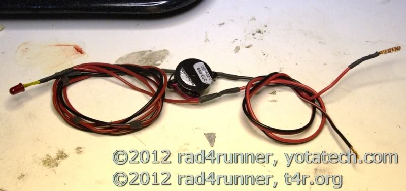
To Install:
Remove Left hand dash panel that covers the instrument panel and holds the Clutch Safety Cancel switch.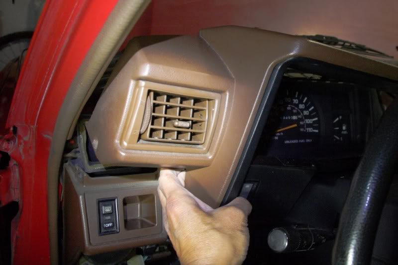
Wher to get positive 12V power
Remove left-hand kick panel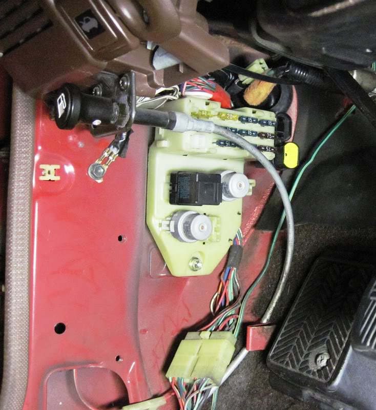
Remove Tail Fuse (15A). Verify that left terminal (marked below) is the supply side by measuring +12V when tail light switch is in ON position, 0 volt when tail light switch is OFF. It is important that you connect to supply side of fuse so that IF headlight is on and even if tail fuse is blown, this will still power the reminder circuit.
NOTE: THIS IS JUST TO SHOW WHERE TO CONNECT. I EVENTUALLY SOLDERED TO THE BACK OF FUSE BLOCK.
Slip red wire into supply side, and re-install fuse. Be careful that you do not cut strands that might fall on other circuits and cause shorts.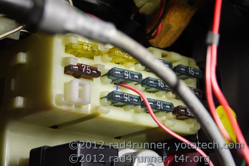
NOTE: The cleaner method would be to solder it into the circuit in the back of the fuse block, which I would do later.
An option is to take positive voltage from this green wire (the section in yellow heat-shrink) that once supplied stock deck lamp circuit, but I disconnected in order to do my deck lamp retrofit. Verify that this green wire has 12V when, and only when, tail light is on.

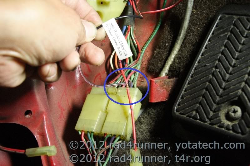
Strip door courtesy switch wire at a convenient spot and connect ground side of circuit to that. Soldering then insulating with heat-shrink tubing or electrical tape is recommended.
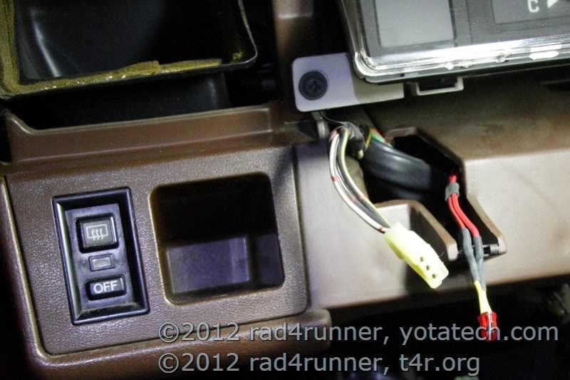
Here's the circuit connected and properly labeled. Buzzer is stuck on fuse block with foam-backed tape. [Let us keep our wiring and and mods clean & properly documented to make it easy to troubleshoot or return to stock when needed/desired. This way our classic rigs can be considered improved, not molested. ]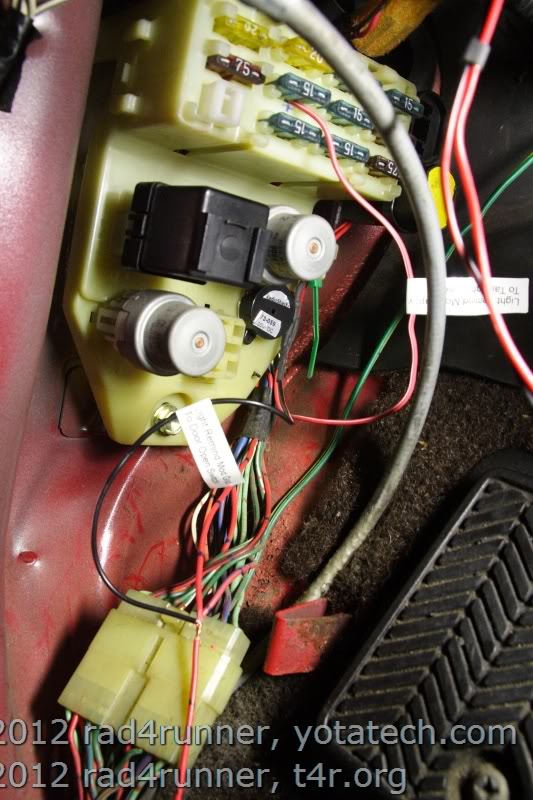
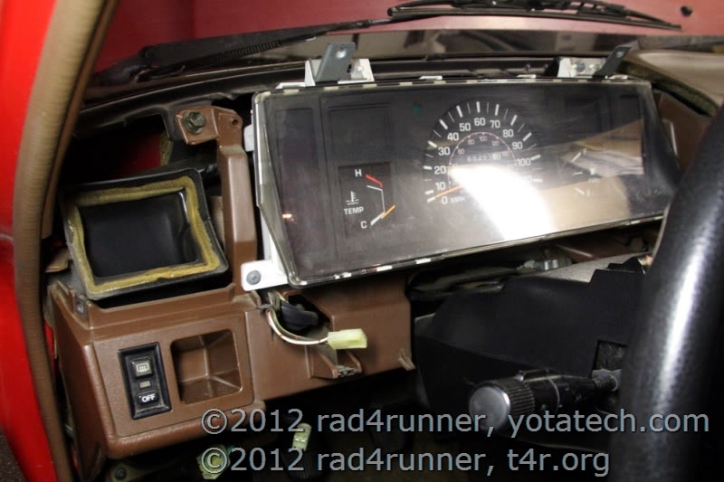
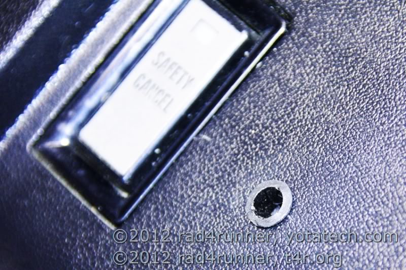
Route LED next to clutch safety cancel switch:
Drill hole and install LED indicator or LED bezel, as applicable, next to clutch safety cancel switch opening.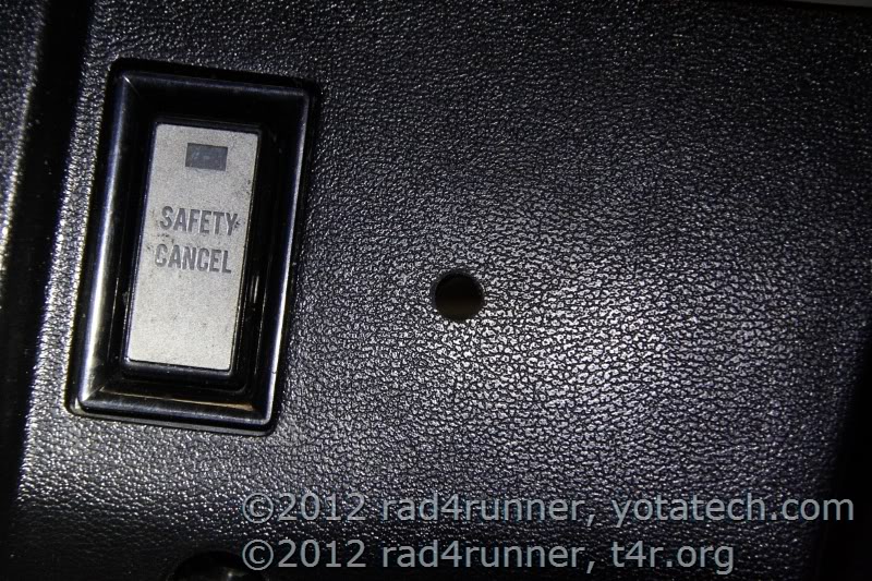
Here is the LED mounted and lit when tested: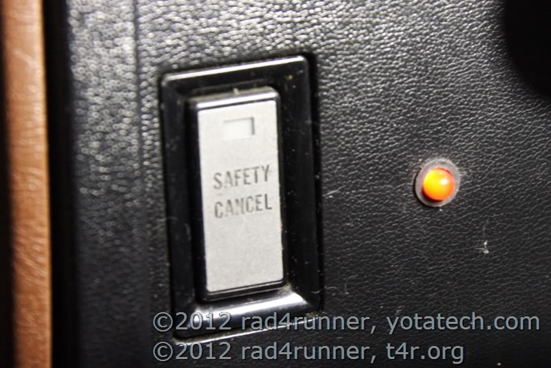
I'm concerned about leaving my lights on and draining the battery. Per FSM, the light reminder relay is supposed to be here, but I only see a mounting hole on mine, confirming my suspicion that the light reminder circuit was only available on SR5 first-gens. Therefore, one lazy afternoon, I got busy
The circuit is simple. It will energize when there is positive voltage from the tail light circuit AND ground via the the driver side door courtesy switch when door is opened. (When headlights are on, there is also power to tail light circuit.)
Parts & Equipment Needed:
- Buzzer PN 273-059 from Radioshack. I used an overhand knot and ran lead wire through mounting hole for strain relief. Also affixed foam-backed double-sided tape for mounting.
- LED indicator light. (I used an LED lying around in my toolbox and appropriate resistor.) Easier to simply buy pre-assembled indicator LED light (i.e., from O'Reilly)
- AWG 20 wire,
- Heat Shrink
- Other basic electrical assembly tools & supply
POSITIVE side will be tapped into tail light circuit between the tail light relay and the 15-amp tail fuse here:
GROUND side will be connected to the door courtesy switch ( provides ground when door is opened) here:
Assembled circuit is shown here:
To Install:
Remove Left hand dash panel that covers the instrument panel and holds the Clutch Safety Cancel switch.
Wher to get positive 12V power
Remove left-hand kick panel
Remove Tail Fuse (15A). Verify that left terminal (marked below) is the supply side by measuring +12V when tail light switch is in ON position, 0 volt when tail light switch is OFF. It is important that you connect to supply side of fuse so that IF headlight is on and even if tail fuse is blown, this will still power the reminder circuit.
NOTE: THIS IS JUST TO SHOW WHERE TO CONNECT. I EVENTUALLY SOLDERED TO THE BACK OF FUSE BLOCK.
Slip red wire into supply side, and re-install fuse. Be careful that you do not cut strands that might fall on other circuits and cause shorts.
NOTE: The cleaner method would be to solder it into the circuit in the back of the fuse block, which I would do later.
An option is to take positive voltage from this green wire (the section in yellow heat-shrink) that once supplied stock deck lamp circuit, but I disconnected in order to do my deck lamp retrofit. Verify that this green wire has 12V when, and only when, tail light is on.
Strip door courtesy switch wire at a convenient spot and connect ground side of circuit to that. Soldering then insulating with heat-shrink tubing or electrical tape is recommended.
Here's the circuit connected and properly labeled. Buzzer is stuck on fuse block with foam-backed tape. [Let us keep our wiring and and mods clean & properly documented to make it easy to troubleshoot or return to stock when needed/desired. This way our classic rigs can be considered improved, not molested.
]Route LED next to clutch safety cancel switch:
Drill hole and install LED indicator or LED bezel, as applicable, next to clutch safety cancel switch opening.
Here is the LED mounted and lit when tested:
Last edited by RAD4Runner; Sep 27, 2021 at 10:26 AM.
Apr 16, 2012 | 08:50 AM
#5
Thread Starter
Registered User
Joined: Mar 2012
Posts: 7,125
Likes: 681
Apr 17, 2012 | 10:41 AM
#6
Thread Starter
Registered User
Joined: Mar 2012
Posts: 7,125
Likes: 681
Disabling Annoying Seat Belt Buzzer
I do not need a reminder to put on my seatbelt, and that buzz is really annoying. However, I do want the "Key left in Ignition" warning.
I did not have a light reminder feature so I made one myself (posted above).
This 5-minute mod:
Find the seatbelt warning cord close to where seatbelt bolts into the floor, in rear, right-hand corner of the driver seat mount.
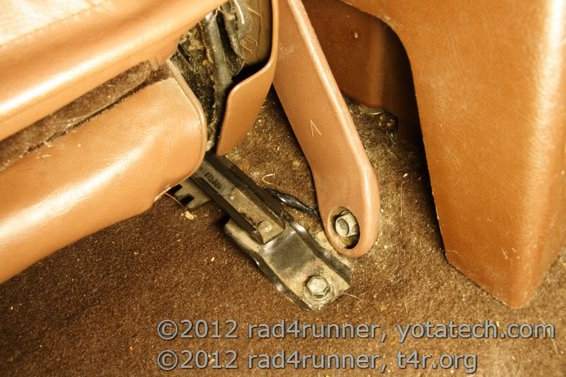
Pull connector from under the carpet.
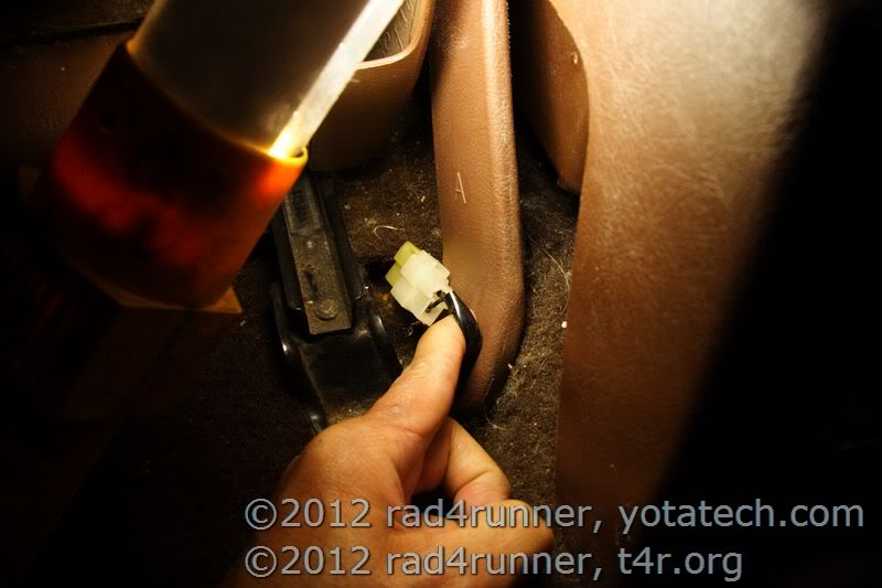
Disconnect
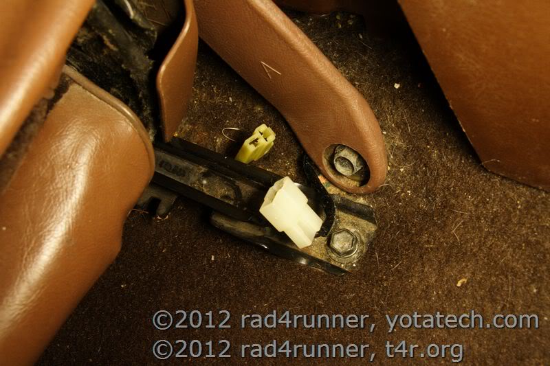
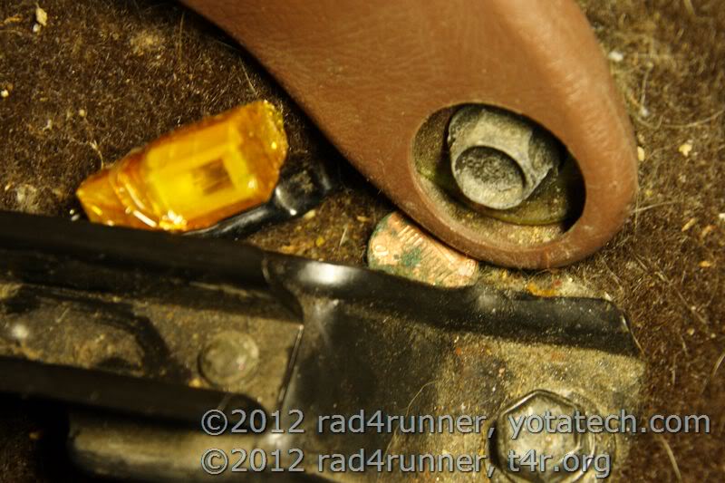
Tape off before Abe -that missing penny - finds and shorts it.
Tuck it back into the carpet.
Now the buzzer will only come on IF, and only IF, Door is open AND key is in the ignition.
I did not have a light reminder feature so I made one myself (posted above).
This 5-minute mod:
- Eliminates the seatbelt buzzer,
- Leaves the useful "Key in Ignition" warning (only on if door is open AND key is in ignition)
- Leaves your components and rig stock.
- Does not require acrobatics to get to that buzzer assembly under the dash.
Find the seatbelt warning cord close to where seatbelt bolts into the floor, in rear, right-hand corner of the driver seat mount.
Pull connector from under the carpet.
Disconnect
Tape off before Abe -that missing penny
- finds and shorts it. Tuck it back into the carpet.
Now the buzzer will only come on IF, and only IF, Door is open AND key is in the ignition.
Last edited by RAD4Runner; Jun 1, 2012 at 06:25 AM.
Apr 17, 2012 | 10:19 PM
#7
Thread Starter
Registered User
Joined: Mar 2012
Posts: 7,125
Likes: 681
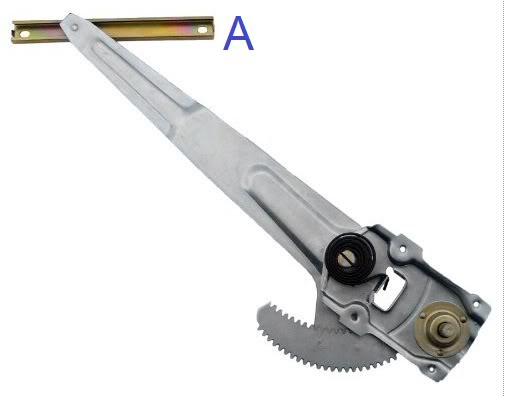
Replacing Manual Window Regulator
Driver Side Window on mine needed help going up or down, and I could feel gears slipping so I purchased replacement window regulator through Amazon. When you do, make sure you chose one that matches your year-model, with vent or without, driver side or passenger side. The process is so simple, is described in the FSM, and can be done in less than an hour, that I did not bother to take many pics. However I hope this couple of sketches may help give you the confidence :
Door panel removal is described in FSM. Fasteners merely pop out. (When they finally wear out on me, I'll replace them with screws.)
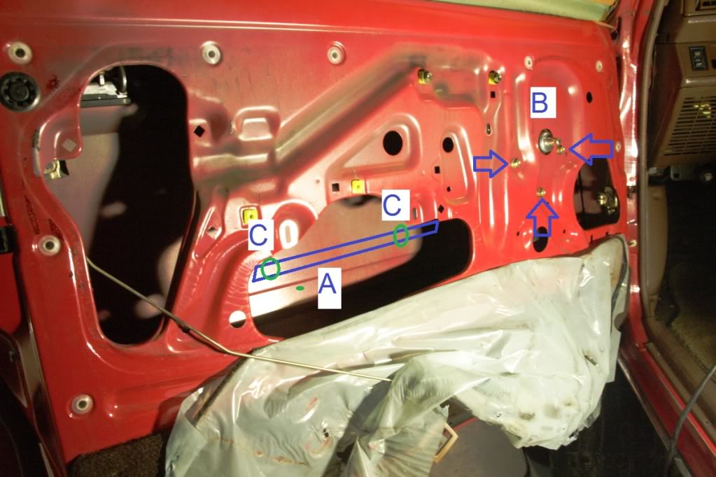
Remove door latch handle (1) by removing screws (2 in 2 places) with 10-mm socket. Peel off moisture barrier sheet while avoiding tears and preserving the gum-like adhesive.
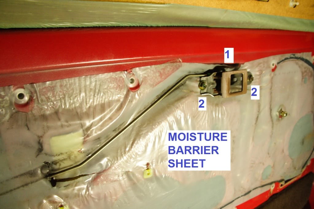
Before removing regulator mounting bolts (B, 3 places), aid the window down until you see the horizontal rail (A) coupling glass to regulator arm and can access two bolts (C, 2 places).
Prepare replacement regulator by greasing all gears/sprocket and other sliding surfaces.
Loosen bolts (C) with 10-mm socket-ratchet.
Loosen regulator mounting bolts (B) with 10-mm sockets.
While holding regulator with one hand, complete removal of all 5 bolts. There should be enough friction for the glass to stay still. If there isn't prepare something to hold it in place. Styrofoam blocks would be one of the safest ways.
Pull old regulator out.
Replacement follows exact opposite process.
Now, enjoy the summer breeze in your hair / or scalp
: Door panel removal is described in FSM. Fasteners merely pop out. (When they finally wear out on me, I'll replace them with screws.)
Remove door latch handle (1) by removing screws (2 in 2 places) with 10-mm socket. Peel off moisture barrier sheet while avoiding tears and preserving the gum-like adhesive.
Before removing regulator mounting bolts (B, 3 places), aid the window down until you see the horizontal rail (A) coupling glass to regulator arm and can access two bolts (C, 2 places).
Prepare replacement regulator by greasing all gears/sprocket and other sliding surfaces.
Loosen bolts (C) with 10-mm socket-ratchet.
Loosen regulator mounting bolts (B) with 10-mm sockets.
While holding regulator with one hand, complete removal of all 5 bolts. There should be enough friction for the glass to stay still. If there isn't prepare something to hold it in place. Styrofoam blocks would be one of the safest ways.
Pull old regulator out.
Replacement follows exact opposite process.
Now, enjoy the summer breeze in your hair / or scalp
Last edited by RAD4Runner; Apr 17, 2012 at 10:33 PM.
Trending Topics
Apr 18, 2012 | 12:25 PM
#8
Thread Starter
Registered User
Joined: Mar 2012
Posts: 7,125
Likes: 681
ZUK's Next!:)
"Thank you for your business and your quick payment. Your 120# Springs will be sent out today ...we are in Arkansas...Thanks again, God Bless, AJ
May 1, 2012 | 12:52 PM
#10
Thread Starter
Registered User
Joined: Mar 2012
Posts: 7,125
Likes: 681
Front-Diff Exercise Lunch
I still need to fix the sag so could not do real off-roading. However, I needed to take the front diff for a spin to help keep seals lubricated so I took her out to lunch here. May-Gray is here.

Special thanks to everybody who has given me tips on getting her restored/enhanced.
Special thanks to everybody who has given me tips on getting her restored/enhanced.
Last edited by RAD4Runner; Jul 26, 2012 at 12:08 PM.
Jul 2, 2012 | 06:31 PM
#13
Thread Starter
Registered User
Joined: Mar 2012
Posts: 7,125
Likes: 681
Corrosion On Battery Connector
Do Not underestimate what simple corrosion can do.
I tried to start the truck, all I heard was cranking momentarily and stopping then all lights and indication of power went out, except for the dome light. Suspecting discharged battery, I jump started with our Corolla, then drove around the block. Before I got back in the garage, I accidentally released clutch too fast so it stalled. It would not start again. No headlight, no radio. My skinny 135-lb a$$ pushed it all the way back into the garage to start more troubleshooting.
To double-check battery, I measured 12.5VDC at the battery post itself with lights out. I turned headlight switch on and still measured 12.5V at battery post itself while headlight remained off.
I happened to probe right IN the interface between terminal post and connector (orange in drawing below). Probe sparked and headlight came on!
Lesson Learned:
Even the lightest, non-obvious corrosion could throw one's troubleshooting off. That corrosion was basically insulating my connector from the post (like electrical tape wrapped around the post would).
Connections should have shiny bare metal contacting shiny bare metal. Gray metal is not good connection.
Last edited by RAD4Runner; Feb 16, 2017 at 04:05 PM.
Jul 2, 2012 | 08:08 PM
#14
I like to use marine terminals and put a little vaseline or motor oil on the terminals to try and keep corrosion down. Do not like having no start issues and having to reset clock and radio preset buttons.
When doing a tuneup and oil change, I suggest just giving the battery a quick look over. Also when I buy a new battery, I try to get the most Cold Cranking Amps as possible. May be a little overkill, but sure beats having a dead battery in severe cold.
When doing a tuneup and oil change, I suggest just giving the battery a quick look over. Also when I buy a new battery, I try to get the most Cold Cranking Amps as possible. May be a little overkill, but sure beats having a dead battery in severe cold.
Jul 2, 2012 | 08:38 PM
#15
Thread Starter
Registered User
Joined: Mar 2012
Posts: 7,125
Likes: 681
I like to use marine terminals and put a little vaseline or motor oil on the terminals to try and keep corrosion down. Do not like having no start issues and having to reset clock and radio preset buttons.
When doing a tuneup and oil change, I suggest just giving the battery a quick look over. Also when I buy a new battery, I try to get the most Cold Cranking Amps as possible. May be a little overkill, but sure beats having a dead battery in severe cold.
When doing a tuneup and oil change, I suggest just giving the battery a quick look over. Also when I buy a new battery, I try to get the most Cold Cranking Amps as possible. May be a little overkill, but sure beats having a dead battery in severe cold.
Will will surely try marine terminals next time I need to replace battery connectors.
Agree. I also have conductive silicone carbon grease similar to this. Will put that on contact surfaces.
Jul 5, 2012 | 02:22 AM
#17
I just stripped a truck and seems that is where the light remider did bolt up. It was on Passenger side. Appreciate you showing how to jump the Fuel Pump Connector. Sure I will run into it someday.
Dumb question, how do you add the drawings into your pics? Thanks
Dumb question, how do you add the drawings into your pics? Thanks
Jul 13, 2012 | 10:41 PM
#18
Thread Starter
Registered User
Joined: Mar 2012
Posts: 7,125
Likes: 681
Sorry just saw you post. (So swamped at work.) Thanks for the confirmation, yeah, FSM shows the relay on that side, but missing on mine.
I just open the jpg file and edit it using old-school Microsoft Paint -
Jul 20, 2012 | 05:22 PM
#19
Thread Starter
Registered User
Joined: Mar 2012
Posts: 7,125
Likes: 681
Starting Circuit Wiring BLUNDER Explained
What electrical engineering blunder am I talking about?
Good intention:
The starter relay was added in Mid-86's to 88 4Runners, to:
However, as you can see from schematic, the start relay control current (in green) and higher current to energize starter solenoid (in orange) both pass through ignition key "start"/ST1 contacts ("A" in schematic), the contacts that the starter relay was meant to protect, in the first place. BIG DUH!
AFFECTED MODELS LISTED HERE
HOW TO FIX IT IS HERE
Good intention:
The starter relay was added in Mid-86's to 88 4Runners, to:
- Allow low current (from ignition switch "start" position energizing start relay coil) to control a higher current required to energize the coil of the starter solenoid. Solenoid needs around 12 amps (verified) to actuate the plunger and clutch that engages flywheel with starter gear.
- Relieve the "start"/ST1 contact of the high current, and help extend its life,
However, as you can see from schematic, the start relay control current (in green) and higher current to energize starter solenoid (in orange) both pass through ignition key "start"/ST1 contacts ("A" in schematic), the contacts that the starter relay was meant to protect, in the first place. BIG DUH!
AFFECTED MODELS LISTED HERE
HOW TO FIX IT IS HERE
Last edited by RAD4Runner; Jun 21, 2020 at 04:21 PM. Reason: Mod Done. Will post pics/schematic later.
Jul 21, 2012 | 06:00 PM
#20
Thread Starter
Registered User
Joined: Mar 2012
Posts: 7,125
Likes: 681
How Starting (Cranking) System Works
I hope this simplified explanation (specific to 1986-1988 4Runners but same concept as others) could help fellow Yota owners who struggle with starting (cranking) issues. Before wasting money and time unnecessarily replacing parts, it helps to understand how the system works. NOTE that wiring for mid-1986 to 1988 4Runners/Trucks with 22R-E, as shown on this schematic is flawed. However, the concept is still valid.
Voltage drops/Corrosion/Resistances
Pitting/corrosion of switch or relay contacts will cause too much resistance across them, that altho relay clicks, you may not be getting full power though it.
Poor (loose/corroded/pitted) contacts have high resistance. It is quite possible to have high resistance on ignition switch ST1 contacts, relay contacts, solenoid contacts, and wire connections, including ground straps. This will result in too much voltage drop across the contacts when there is current flowing through it.
Starter solenoid needs high current through its coil in order to actuate the plunger. Even if the individual components of the starting system seem to work/energize/click, there may be too much voltage drop across these components. Once you add up these voltage drops, you may end up with too little voltage (hence current) to energize the starter solenoid.
A starter that works when smacked could mean:
BIG BOO-BOO:
Note on schematic that starter solenoid control (coil) power is also taken from ignition switch ST1 contact, same contact that the start relay is supposed to relieve of the solenoid control current in the first place - DUH!
This wiring flaw is explained in detail here
- Putting Ignition switch (A) in "Start" position sends power (low current in green) to energize starter relay (located here). Have someone start the truck and listen to/feel the starter relay click. It also sends power to Circuit Opening Relay to start fuel pump, but that's a separate system. The COR is the relay that you hear click behind the glove compartment (barely visible here), when you try starting.
- Starter relay contacts close sending power (higher current, 12 Amperes on my 1986 4Runner) to starter solenoid though this connector, that plugs into starter solenoid here. (Starter solenoid piggy-backs on starter.)
Starter solenoid has larger coil than a relay because it has to pull in a plunger that closes heavier starter contacts to handle extremely large cranking current, and actuate clutch to engage flywheel and starter gears.
- Starter solenoid contacts sends extremely high cranking current (in red in schematic) from heavy wire directly connected to the battery to starter to turn it.
Voltage drops/Corrosion/Resistances
Pitting/corrosion of switch or relay contacts will cause too much resistance across them, that altho relay clicks, you may not be getting full power though it.
Poor (loose/corroded/pitted) contacts have high resistance. It is quite possible to have high resistance on ignition switch ST1 contacts, relay contacts, solenoid contacts, and wire connections, including ground straps. This will result in too much voltage drop across the contacts when there is current flowing through it.
Starter solenoid needs high current through its coil in order to actuate the plunger. Even if the individual components of the starting system seem to work/energize/click, there may be too much voltage drop across these components. Once you add up these voltage drops, you may end up with too little voltage (hence current) to energize the starter solenoid.
A starter that works when smacked could mean:
- Starter solenoid plunger mechanically hard to actuate and there is not enough current to move it, because of resistance in circuit. Smacking may get it unstuck.
- Plunger actuated and attempts to close contacts but because contacts are pitted/worn out it takes a little help to make them close all the way.
- Starter motor mechanically stuck, bad brushes, bad winding, etc.
BIG BOO-BOO:
Note on schematic that starter solenoid control (coil) power is also taken from ignition switch ST1 contact, same contact that the start relay is supposed to relieve of the solenoid control current in the first place - DUH!
This wiring flaw is explained in detail here
Last edited by RAD4Runner; Jul 27, 2016 at 09:20 PM.


