When you click on links to various merchants on this site and make a purchase, this can result in this site earning a commission. Affiliate programs and affiliations include, but are not limited to, the eBay Partner Network.
Hey buddy,
I MIGHT SUSPECT that ur fuel filter is hindering flow.... but then it runs perfectly fine at times, right? ...
Originally Posted by Terrys87
I would feel your Timing Switch is probably most at fault but it could be the injector as well. From my experience it is the Timing Switch that will go bad first...
Thanks for the inputs, guys! Nothing's broken Looks like it's a case of loose connector that explains only one occurrence- in Sacramento after Shasta climb last June - then it did not happen again until February.
This is another example of sloppy workmanship of whoever touched this part last.
Glad to see you got it fixed and it wasnt anything major. To do the repair right the first time takes just about as long to do it sloppy. Never did understand that, but seems to be a common problem with these trucks.
Glad to see you got it fixed and it wasnt anything major. To do the repair right the first time takes just about as long to do it sloppy. Never did understand that, but seems to be a common problem with these trucks.
Tnx, Terry. Exactly, that's why I don't understand why many people asking for help ask if they could get away with a shortcut.
what if i have a brand new starter, and im gettin plenty of power from the battery, and it will rarely start, i havent beat on the new starter, and really dont want to, i wanna try the bypass but im not sure if thats the actual problem, any advice would be appreciated.
its an 87 Pick up, i know for sure that the starter relay is clicking, and so is the starter selenoid. Someone on the forum said something about a worn key, is that likely?
A worn key means ignition switch, but i Circuit Opening Relay, starter relay, and starter solenoid click, ign switch is good. If battery and ground connections to starter are good, then you probably have bad solenoid contacts, bad starter winding or brushes.
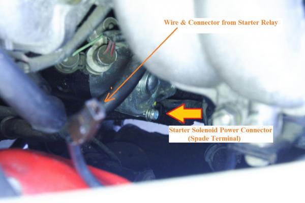
Just to double-check, disconnect brown connector from starter solenoid. There will be male spade terminal ON the solenoid. Connect that male spade connector directly to battery.
If solenoid thunks but no crank. Then it's either bad solenoid contacts, bad starter winding or brushes.
Tnx, Mark! Busy but good. Too many things going on (and coming from different directions LOL!) at the same time; I haven't made progress on my headlight wiring retrofit.
This fixes the poor wiring design on early Toyota trucks, while retaining the switched-ground system that will allow Truck-lites to plug-and-play into the first-generation 4Runner and those with similar headlight housing and circuits.
To minimize additional parts I rewired the headlight circuit, instead of buying or making an add-on h4 conversion harness.
Stock:
Wires are thin (AWG 18/20?)
Ground circuit goes from bulbs, to cabin, to dash to dimmer switch, back to engine compartment to ground inside passenger-side fender - What 4crawler calls a convoluted path (http://www.4crawler.com/4x4/CheapTri...adlights.shtml) - causing a lot of resistance, a lot of voltage drops and reducing power that actually reach the bulbs.
Dimmer (combo) stalk switch contacts carry high current (10 Amps on 60-watt high beam, 17 Amps on 100-watt high beams). This will shorten contact life.
MY SOLUTION:
Used only one additional part, a 5-pin relay, plus solder & wiring supplies.
Uses existing headlight fuses
Upgraded to thicker 12AWG wires, from fuses to ground
Ground path goes directly from bulb to relay to fender ground (relay pin 30), minimizing voltage drops.
Relay, not the dimmer combo switch, carries headlight current, helping extend dimmer switch life.
Using normally-closed contact 87A replicates stock circuit for low beam. Even IF coil of the added relay or wiring to it fails, low beam will still work.
STOCK
IMPROVED
(Stock wiring is in black. Red "X"'s are where I cut stock wiring.)
Procedure:
I replaced all thin stock wire (in yellow rectangles) from headlight fuses to positive side (pin 3) of bulbs. This is optional. Just physically trace wires and replace.
Looking at colored wire:
Bulb pin 1 (low beam) was disconnected from dimmer contact "HL" and moved to normally-closed relay contact 87A, This contact now provides ground to pin 1 to turn on low beam.
Bulb pin 2 (hi beam) was disconnected from dimmer contact "FU" and moved to normally-open relay contact 87. This contact now provides ground to pin 2 to turn on high beam.
Pin 5 ("FU") of dimmer switch connected to negative side of added relay (pin85).
Operation:
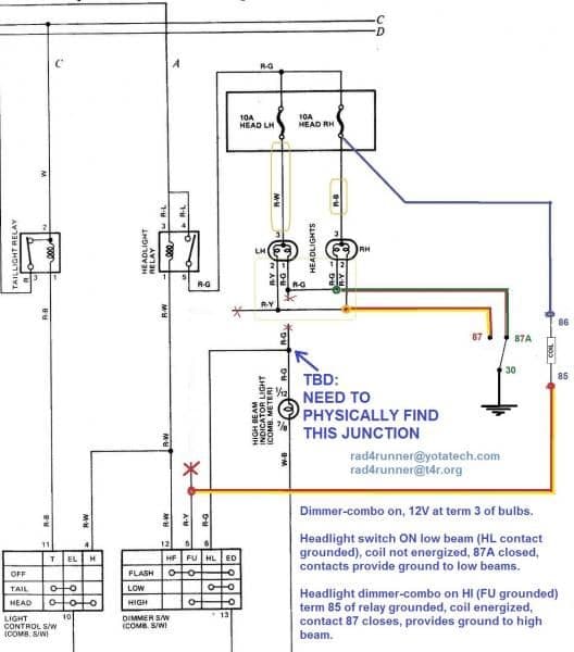
When switch is turned to low-beam on, headlight relay closes providing +12V to pin 3 (common) of bulb AND positive Pin 86 of added relay. Relay coil negative (pin 85) floats = it does not get ground so relay stays OFF. Normally-closed contact 87A of relay already provides ground to pin1 (low-beam) so low beam comes on. (In stock circuit, contact HL of dimmer switch combo (stalk) provided this ground and carried the high current.)
When dimmer switch stalk is pulled to "flash" momentarily or pushed forward to turn on high beam, FU contact of dimmer provides ground to negative side of added relay and turns relay on. Contact 87 closes, provides ground to pin 2 (high-beam) of bulb and turns on high beam. (contact 87a opens and low beam turns off.)
Voltage Drop Comparisons:
With Sealed Beam & Engine off
Stock Wiring
Low Beam:
Batt: 12.05V, Across low beam filament (pins 1 & 3): 11.15V
Voltage drop in wiring: 0.9V
volt drop = 7.5% of battery voltage
High Beam:
Batt 11.94, Across high beam filament (pins 2 & 3): 10.07
Volt drop: 15.7% of battery voltage!
After Retrofit:
Low Beam:
Batt: 12.31V, : Across low beam filament (pins 1 & 3): 12.11V
Volt Drop: 0.2 = 1.6% of Battery voltage
High Beam:
Batt: 12.24V, Across high beam filament (pins 2 & 3): 11.78V
Voltage drop: =0.46V = 3.75% of battery voltage
Still To Do: Still debating what to do with high-beam indicator. Long story.
Got a question for you. Not something I would like an answer to right away and I will see what info and pics I can find for you and will post them when I do. On my 85 thread, it was brought up that the 94s alternators are 120 amp. I have asked two knowledgeable guys about Toyotas and one told me that they are the same alternators but the plug is different and neither could give any more information.
I have been checking the yards looking for a 94 to see what the alternator looks like and will start looking for the circuit diagram for the same alternator. Looks like to me if this is the case and you could just swap wiring connectors, this would be a much better way to go then the GM upgrade. You could still use the Toyota mounting brackets and stay with Toyota parts. Right now we dont have any 94s in the yards. I have acess to about 12 different Toyota trucks in all and of course none are 94s. Two are 3rd gen runners and everything else inbetween.
I am sure as long as Yotatech has been around, that someone may have tried to do something like this, but I have searched some and havent been able to come up with anything yet.
I am in no hurry and should be able to play on the internet tomorrow as we are getting sleet and snow and will be to cold to do anything outside. I will try and get some measurements on Mistys runner about the springs settling as well. She has since swapped from the tires and rims from when I did the Zuk Mod but should be able to measure from the rims to the fender lip and such.
I would just like your opinion on the 94 alternator upgrade and if it is possible. You are able to sort out the circuits and let me know if it is a possible option and if it would or wouldnt work.
Dude, get up here and get my headlights wired for "smart lighting"! Haha. ... Seriously though, Congratz!
Terry, never heard that one, interesting. I found those often. ... Not 95, not 93,..... just 94? I know I've heard that some year MR2's run either 90 or 120A Alt's..... Got me curious bubba
That Splice for the Lamp indicator is maybe "I6", located between the bottom of the column and the center of the dash before it goes into the "square" plastic tube. Taken from the 95 4runner EWD, so might not be accurate for your model year but sounded plausible.
I can't read the sticker on my alternator, too dark and backwards in the mirror just too difficult.
That Splice for the Lamp indicator is maybe "I6", located between the bottom of the column and the center of the dash before it goes into the "square" plastic tube. Taken from the 95 4runner EWD, so might not be accurate for your model year but sounded plausible.
Thanks a lot, Co_94_PU!
Final analysis, i could not really find a point which would be 12V only when High beam is on because of the switched-ground configuration so. I guess I have no choice but to "sink" the voltage to ground when Low Beam is on (= terminal 87A is grounded). I will just connect High beam indicator supply wire (R-G)to that, but put a resistor (27-ohm maybe) so relay contact (path of least resistance), not the dimmer switch will take the burden of "sinking".
Disconnect plug-C pin6 (R-g) at the bottom of the steering column, move A2 pin3(relay block, R-g) to Relay pin 87 (Or A2 pin 1, R-y).
But then there would be abit of voltage division going on, huh. Swap out the Lamp indicator with a high resistence LED
That is what you are already planing I think actually. It just kind of read as "1 + X = 3" instead of "1 + 2 = 3". Maybe I just need to break off for dinner
If you hook it to the high beam side of the relay it won't be wasting power as heat (shuting to ground).
Hey Ray, when you have some time can you give me a little explanation about this alternator. I'm looking at replacing my stock one with this. I don't have to send in my current one, so I don't mind giving it a try to see how long it lasts.
I asked him what the amp output would be at idle and he stated around 75. What I'm hoping you could explain is the "diode" specs he has listed...what the heck does that have to do with anything?
http://www.ebay.com/itm/150667921168?item=150667921168&viewitem=&vxp=mtr
They are pretty local to me and have a brick and mortar store also, so another plus in case something goes wrong. Ace Alternators & Starters / 13201 Imperial Hwy, Whittier, CA.
Diodes? YEAHHHH BOOOOEY! .... wait, what? Haha. .. jk, but wondering if the 8 diode set up is to help avoid any(or at least less risk) back flow/surging, blowing things up? Maybe preventing overheating of the alt as well? Just guessing for the heck of it. Lol
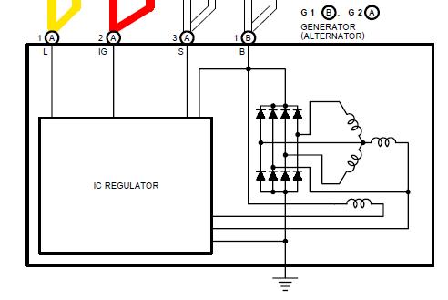
The diodes are the eight triangle-with-bars bits. 8 is the standard configuration for these.
The Amp rateing given is just some random "geek speak" to awe and amaze you, it's not usefull information since it doesn't say if it is average or maxium. Usefull information would include both avg and max, or even better a part number and company.
The current is limited by the coil resistences (Three squiggly bits to the right), and the diodes should be rated accordingly.
Soo assuming an equal 1/3rd share of the current 3*55=165 Amp, but again it's limited by the coil resistence. These are borderline over sized at 5-20%.
I mentioned I suck at power calculations No not today well I do!
Anyways the usual safety margins are 1.25-1.50 times average and 2.5 times maximum current. So 138 /3 * 1.25 = ~57A avg or 115A surge ratings.
Thanks, Co_94_PU! Yeah, both - LOL!
Agree, guys. Marketing stuff. Would not know really until the alt is put to the test. Turn on all possible loads, read current with clamp-on ammeter, monitor charging voltage if it drops, see, smell if anything smokes.
Good thing is they're local.
Last edited by RAD4Runner; 04-03-2013 at 08:30 AM.
 03-24-2013, 09:31 PM
 Looks like it's a case of loose connector that explains only one occurrence- in Sacramento after Shasta climb last June - then it did not happen again until February.