
Hello! +wiring issue ...
 04-27-2014, 01:00 PM
#1
Registered User
Thread Starter

Join Date: Jan 2010
Location: Nova Scotia
Posts: 9
Likes: 0
Received 0 Likes
on
0 Posts
Hello! +wiring issue ...
Hello all! Already learned a lot from reading forum, so now joined- with problem, obviously ...
1988 4wd ext cab 22re manual trans
Previous owner was definitely a po ... a symptom-fixer, not a problem solver. (Eg- no power to fuel pump, so scraped insul off single line from starter resistor (about 1/2" from resistor) tied overhand knot in 'new' wire, silicone booger over, ran it all over back to tank, cut blue wire and gobbed 'new' one on ...)
Inspection time coming, so I went after rear light issues: much the same cobble all over, so I tore the whole works out- connector under passenger seat was broken and melted, more cobbling to jump over it ... I cut the entire harness out of my 92 parts truck, soldered in to replace both sides of connector, cleaned harness put it in a loom and taped it up. Everything works fine, but no back-up lights, no power at fuel pump. Checked COR as per Haynes book, says good. When I jump B-Fp on COR connector, I get power at pump- so still a work in progress.
On to back-up lights. Found https://www.yotatech.com/forums/f131/rewire-...switch-255165/ and Hadmatt54 (post #7) to get to connector N3. Said connector is totally rotten- took 45 min to get apart- ball of green powder, pins rotted off etc. I was delighted- not every day you find an obvious issue the first place you look :-) Back to 92 parts truck, cut out connector with lots of wire.
Which is where fan jumped into dung pile. I tried my best to draw a map of what colour went in on male pin side, and what colour comes out female side- (they are not all the same)- not easy- the first two I touched fell apart. So I cut one matching pair of wires at a time, soldered into 'new' connector lines, meter checked before heat-shrink. All good.
Yay! I get back-up lights. Boo! Still no power at fuel pump. Added bonus: now when I jump B-Fp on COR connector, the starter relay (I think) clicks up in engine compartment ...
So obviously, since it's the only thing I changed, I must have somehow mis-matched the N3 feeds. Thus my question: where do I find the colour-in and colour-out map for the N3 plug- there are not a lot of similar trucks around here, and Toyota seems to have cleaned out the junkyards in their 'hide the bad frame' frenzy.
Hope someone can help
 04-28-2014, 01:05 AM
#2
Super Moderator
Staff
iTrader: (1)
Join Date: Aug 2008
Location: Anderson Missouri
Posts: 11,788
Likes: 0
Received 21 Likes
on
19 Posts
I would prop the AFM flap open then turn on the key and see if you can hear the fuel pump on. This will engage the COR as well. If still no power, like you suspect, it is most likely a wiring issue. I don't know about finding which colors of wires go where. If you can eventually find the harness that goes from under the passenger seat all the way to the tail lights, I would change it out. It is easily done and would get rid of the previous owners poor repairs.
04-28-2014, 03:18 AM
#3
Registered User
Thread Starter
Join Date: Jan 2010
Location: Nova Scotia
Posts: 9
Likes: 0
Received 0 Likes
on
0 Posts
I guess I wasn't very clear ... my bad. The entire harness from pass seat to back bumper has been replaced, meter-checked, works fine. There is no power to pump, and I'm quite confident that it is indeed a wiring issue that I created at the N3 connector. I guess what I'm looking for is someone mid-build who could take a look at an undisturbed connector and post the colour-matching
04-28-2014, 01:40 PM
#4

 04-28-2014, 09:43 PM
#5
 Just depends where you got the harness from if it is the same year as yours your good.
if it is not you would need to know what year then sit down and merge the two years.
It is funny the plugs can be the same but the wire colors change between years at times.
04-29-2014, 06:41 PM
#6
Registered User
Thread Starter
Join Date: Jan 2010
Location: Nova Scotia
Posts: 9
Likes: 0
Received 0 Likes
on
0 Posts
Terrys87:
"Located under seat going to tank"- that would be just ahead of where it goes through the rubber boot in cab floor I take it? That's only an in-line coupling of the rear harness.
The one I'm looking for is tucked up below the dash on the right. There are two connectors (mine are yellow) up above/tucked behind the computer behind that passenger's right foot boot guard plastic panel thingy down below glove box. The so-called 'N3' is the smaller of the two: ten pins available, I have nine feeding in, eight going out (the odd one has a male pin but no matching female, so obviously meant for an option I don't have).
My eight 'working' wires are not all the same colour sequence on both sides. Some are: W-B ground is continuous for example. There are colours on one side that aren't on the other side. That's the matching I need.
Last edited by tomd; 04-29-2014 at 06:42 PM.
Trending Topics
05-04-2014, 03:01 PM
#8
Registered User
Thread Starter
Join Date: Jan 2010
Location: Nova Scotia
Posts: 9
Likes: 0
Received 0 Likes
on
0 Posts
making some progress
found an info-donor truck, identical connector wiring- mine was correct :-)
still no power to fuel pump tho ...
looking at COR diagrams at
https://www.yotatech.com/forums/f199.../#post51947160 (Terrys87- you were in on this one too)
Everything checks out (including COR operating on both coils if I jump appropriate contacts) I have no power to Coil 1 through STA pin. It should come from Ign Switch- does it surface anywhere else first I should check, or straight from switch to COR ??
05-04-2014, 06:37 PM
#9
Registered User

You haven't mentioned wether or not if your starter will engage when you try to start. If it does then there is nothing wrong with your ignition switch or your start relay. There is a junction after the start relay in the wiring harness where the feed to the COR is tapped. That might be your problem. It's located about 10" from the COR in the main dash harness.
05-04-2014, 08:20 PM
#10
QUOTE=tomd;52190455]
Previous owner was definitely...(Eg- no power to fuel pump, so scraped insul off single line from starter resistor (about 1/2" from resistor) tied overhand knot in 'new' wire, silicone booger over, ran it all over back to tank, cut blue wire and gobbed 'new' one on ...
... I cut the entire harness out of my 92 parts truck,[/QUOTE]
Concur with Wyoming. First you said you fixed the P.O.'s wiring. Then you used harness from a 92. Did you verify that P.O.'s wiring was correct? If not you could have just been fixing connections to the wrong spots, after all.
Also Did you verify that the 92 harness is wired similar to your 88 22RE?
Since wire color code could change between year-models, and you are not sure if 92 harness is exactly same as 88's, do not trust color coding. you need to physically trace and verify that each and every wire is intact and ends up at the right spot.
Schematic of 22RE wiring is here.
Previous owner was definitely...(Eg- no power to fuel pump, so scraped insul off single line from starter resistor (about 1/2" from resistor) tied overhand knot in 'new' wire, silicone booger over, ran it all over back to tank, cut blue wire and gobbed 'new' one on ...
... I cut the entire harness out of my 92 parts truck,[/QUOTE]
Also Did you verify that the 92 harness is wired similar to your 88 22RE?
Since wire color code could change between year-models, and you are not sure if 92 harness is exactly same as 88's, do not trust color coding. you need to physically trace and verify that each and every wire is intact and ends up at the right spot.
Schematic of 22RE wiring is here.
05-05-2014, 03:15 AM
#11
Registered User
Thread Starter
Join Date: Jan 2010
Location: Nova Scotia
Posts: 9
Likes: 0
Received 0 Likes
on
0 Posts
My only remaining issue is no power at the STA pin in the COR connector when I turn the key to Run (http://www.4crawler.com/4x4/CheapTri...s/FuelPump.gif) Everything else checks out: EFI relay is feeding to B, COR does fire when I jump power to B and ground Fc / power to STA and ground E1, pump does run when I jump power to Fp
Will be investigating Hadmatt54's suggestion this morning
This is one of those wonderful situations where I'm tangled in issues I've never dealt with before, making lots of mistakes and therefore learning a lot, and you are all helping out a lot !!
later
05-05-2014, 11:12 AM
#12
Registered User
Thread Starter
Join Date: Jan 2010
Location: Nova Scotia
Posts: 9
Likes: 0
Received 0 Likes
on
0 Posts
You haven't mentioned wether or not if your starter will engage when you try to start. If it does then there is nothing wrong with your ignition switch or your start relay. There is a junction after the start relay in the wiring harness where the feed to the COR is tapped. That might be your problem. It's located about 10" from the COR in the main dash harness.
Now, this "junction after the start relay in the wiring harness where the feed to the COR is tapped". I'm assuming by "start relay" you're talking the one out on the right inner fender right beside the resistor? I can read schematics pretty well, but don't understand the physical route you've described. From "where the feed to the COR is tapped" does it go directly from the tap to COR or to computer and back on the way?
The reason I'm asking is that when I bought the truck, with carpet and kick panel out, plastic fender splatter shield out of way, I could pretty much reach through and pick loose change off the pass seat (long since cut out and welded in new, including cab mount). The bottom quarter or so of the back side of the computer was rusted totally gone (also long since replaced). The badly corroded connector I've just replaced is also down there. So I'm wondering, not knowing any better, if there might be a rotten connection problem down there somewhere that is breaking the feed to the COR
Last edited by tomd; 05-05-2014 at 11:18 AM.
05-05-2014, 02:22 PM
#13
...
Now, this "junction after the start relay in the wiring harness where the feed to the COR is tapped". I'm assuming by "start relay" you're talking the one out on the right inner fender right beside the resistor?
... From "where the feed to the COR is tapped" does it go directly from the tap to COR or to computer and back on the way?
The "tap" is the black wire from the "ST1": contacts of ign switch. It is NOT ELECTRICALLY AFTER the starter relay. It is Electrically upstream of the starter relay; it supplies power to positive side of relay coil. But again IF you physically trace the wire run, the tap is is be physically closer to the COR than the starter relay is.
Here is that tap on the schematic.
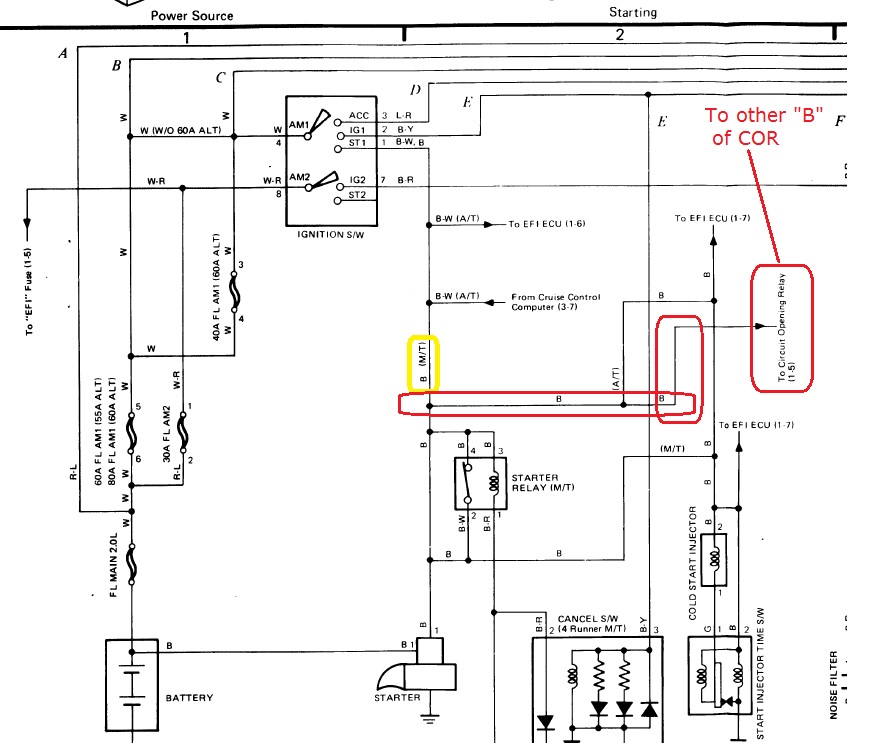
From that electrical point (may not be exact same physical point) there is also a tap to the ECU, but don't worry about that for now.
Here is where that tap connects to the C.O.R.
As far as physically finding the taps, we would not be able to do it for you remotely; Those could vary from model-year to another, The best way is to do it yourself; that's also the best way to your schematic. best of luck,
RAD
Last edited by RAD4Runner; 05-05-2014 at 02:24 PM.
05-05-2014, 04:42 PM
#14
Registered User
Thread Starter
Join Date: Jan 2010
Location: Nova Scotia
Posts: 9
Likes: 0
Received 0 Likes
on
0 Posts
It's even worse than that ... the problem is ... well, I had already solved the problem and didn't realize it- I even documented my own misunderstanding in an earlier post: "My only remaining issue is no power at the STA pin in the COR connector when I turn the key to Run" when, as you point out here https://www.yotatech.com/forums/f199.../#post51939375 "Coil 1 of COR is energized by IGN switch while in START position". Everything has been working perfectly for days since I replaced the corroded connector, and I kept looking for a problem I don't have
Corollary #1 to Rule #1: once it's fixed, stop trying to fix it ...
RTFM is only the first half- Comprehend TFM finishes the job ...
So, lots of lessons learned- I now know stuff I didn't know existed a couple weeks ago- maybe someday I'll be able to help someone else (Gawd help them :-)
Anyways, thanks so much to all of you who helped kick this can down the road.
05-05-2014, 06:14 PM
#15
Registered User
Don't get caught up in the semantics of what component is upstream or downstream. The reality of how harnesses are constructed is that if the circuit you are dealing with is smaller gauge wire for example 22-16 and there are 3 or 4 branches off of this circuit, those branches will most times be from the same junction. It's when you get into the larger wires 14-10 gauge that the junctions are only two or three wires. The junctions that I was talking about in my last post are in the main harness about 10-12" from the grommet where the harness goes through to the passengers inner fender or from N2,N3 and the COR it's about 5" up the branch and then about 5" back towards the drivers side in the main harness.
I just read your newest posts, so I'll try and explain how the COR works.
When you start the vehicle, with the key in start position, ST1 is energized. Current flows (small black wire) to terminal 3 of the starter relay, through the relay coil to terminal 1 ( white/black wire) to ground. The energized coil closes the contact of the starter relay, current now flows (large black wire) to terminal 4 through the closed contact to terminal 2 (large black wire) to the starter solenoid engaging the starter.
At the same time current flows to terminal 3 of the COR through the relay coil to terminal 6 to ground. (Yes 6, this is from a factory wiring diagram book...there is no terminal 5.)
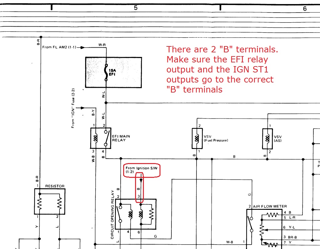
The contact is pulled closed (terminals 2 & 4) and the fuel pump is energized from the EFI fuse and relay for the start. Once the engine starts and the ignition key is in run (or ignition) position ST1 is no longer at 12 volt and current stops flowing through the COR coil across terminals 3 & 6. However in the run position current now flows from terminal 2 (which is already energized) through the contact to terminal 4 of the COR, to terminal 2 of the AFM, through the closed contact (because the engine is running) to ground. This circuit keeps the COR contact closed which keeps the fuel pump running.
" My only remaining issue is no power at the STA pin in the COR connector when I turn the key to Run"
So I don't see where you have a problem! Because there is no voltage at the STA pin of the COR in the run position.
I just read your newest posts, so I'll try and explain how the COR works.
When you start the vehicle, with the key in start position, ST1 is energized. Current flows (small black wire) to terminal 3 of the starter relay, through the relay coil to terminal 1 ( white/black wire) to ground. The energized coil closes the contact of the starter relay, current now flows (large black wire) to terminal 4 through the closed contact to terminal 2 (large black wire) to the starter solenoid engaging the starter.
At the same time current flows to terminal 3 of the COR through the relay coil to terminal 6 to ground. (Yes 6, this is from a factory wiring diagram book...there is no terminal 5.)
The contact is pulled closed (terminals 2 & 4) and the fuel pump is energized from the EFI fuse and relay for the start. Once the engine starts and the ignition key is in run (or ignition) position ST1 is no longer at 12 volt and current stops flowing through the COR coil across terminals 3 & 6. However in the run position current now flows from terminal 2 (which is already energized) through the contact to terminal 4 of the COR, to terminal 2 of the AFM, through the closed contact (because the engine is running) to ground. This circuit keeps the COR contact closed which keeps the fuel pump running.
" My only remaining issue is no power at the STA pin in the COR connector when I turn the key to Run"
So I don't see where you have a problem! Because there is no voltage at the STA pin of the COR in the run position.
Last edited by Hadmatt54; 05-05-2014 at 06:32 PM.
05-06-2014, 02:49 AM
#16
Registered User
Thread Starter
Join Date: Jan 2010
Location: Nova Scotia
Posts: 9
Likes: 0
Received 0 Likes
on
0 Posts
Yup- it's all working just fine. BTW- I had scoured through the FSM schematic in my pdf copy, but hadn't made the conceptual connection between the two pages that you posted. I'll have to print them and tape together- looking at it one page at a time got confusing
back to scraping the frame ...

Thread
Thread Starter
Forum
Replies
Last Post
v_man
86-95 Trucks & 4Runners
14
07-23-2015 04:01 PM


