
Transmission Code 42
 Jan 24, 2009 | 01:09 PM
#22
Thread Starter
Registered User
Joined: Jun 2008
Posts: 735
Likes: 1
From: Abington, PA
Jan 24, 2009 | 05:37 PM
#24

Registered User

Joined: Sep 2007
Posts: 8,380
Likes: 871
From: San Francisco East Bay
I believe that the procedure posted by BoostinChick is for testing the "speed sensor" that goes with the cable driven speedometer. There is a reed switch and magnet up in the panel somewhere, near the speedometer itself. Since it is a passive component, you can test it with an ohmmeter.
But BoostinChick has the all-electronic system (no speedometer cable), and there is no sensor in the dash. Instead, there is a single sensor in the back end of the transfer case. It is held in with a single bolt, and has a three-terminal connector. Internally, it is an integrated hall-effect sensor, so an ohmmeter won't help. To test, you could apply 12v to the correct terminals, and measure the voltage to gnd on the third terminal,
(I've never even tried this; the terminals are difficult to access - I tested it in the other direction, by applying a 12v square wave through a signal generator to the speedometer cable, confirming the speedometer worked, but the sensor didn't. But I'm guessing BoostinChick is not equipped with a signal generator.)
The symptoms described sure sound like mine (which were cured permanently by a new sensor). The trick is that it is an expensive part ($300+ dealership), and I can't imagine a dealer (or anyone else) would let you return an electrical part.
Jan 24, 2009 | 07:55 PM
#26
Registered User
Joined: Sep 2005
Posts: 8,656
Likes: 16
From: NW Ark on wooded ten acres...Ozarks at large!
Here it is. Procedure for testing the dash with an ohm meter.
http://personal.utulsa.edu/~nathan-b.../6combinat.pdf
http://personal.utulsa.edu/~nathan-b.../6combinat.pdf
Jan 25, 2009 | 08:23 AM
#27
Thread Starter
Registered User
Joined: Jun 2008
Posts: 735
Likes: 1
From: Abington, PA
Here it is. Procedure for testing the dash with an ohm meter.
http://personal.utulsa.edu/~nathan-b.../6combinat.pdf
http://personal.utulsa.edu/~nathan-b.../6combinat.pdf
Jan 25, 2009 | 05:48 PM
#29
Thread Starter
Registered User
Joined: Jun 2008
Posts: 735
Likes: 1
From: Abington, PA
Maybe I am just really brain dead:
Does this mean I have to hook up the black/red terminals onto the A and B terminals on the gauge cluster WHILE driving around in order to rotate the speed shaft while in the trans?
2. INSPECT SPEED SENSOR
Check that there is continuity between terminals A and B
four times par each revolution of the speedometer shaft.
If operation is not as specified, replace the speedometer.
Check that there is continuity between terminals A and B
four times par each revolution of the speedometer shaft.
If operation is not as specified, replace the speedometer.
Jan 25, 2009 | 05:53 PM
#30
Registered User
Joined: Mar 2008
Posts: 12,723
Likes: 6
From: Temecula Valley, CA
no. you should have a lift and rack available so you can do that test in your garage.
this is the FSM you're talking about, right... the one's the mechanics in the service department use?
this is the FSM you're talking about, right... the one's the mechanics in the service department use?
Jan 25, 2009 | 05:54 PM
#31
Thread Starter
Registered User
Joined: Jun 2008
Posts: 735
Likes: 1
From: Abington, PA
Ya ya ya...I understand I have neither (I can dream though!). Just unsure/not crafty on how to test the gauge cluster then.
Jan 26, 2009 | 11:51 AM
#33
Registered User
Joined: Sep 2005
Posts: 8,656
Likes: 16
From: NW Ark on wooded ten acres...Ozarks at large!
Did somebody say alligator clips?
(NSFW or kiddies.......)
http://www.youtube.com/watch?v=305vRNoofr8
(NSFW or kiddies.......)
http://www.youtube.com/watch?v=305vRNoofr8
Feb 7, 2009 | 05:46 PM
#34
Thread Starter
Registered User
Joined: Jun 2008
Posts: 735
Likes: 1
From: Abington, PA
So, I just replaced the sensor that's on the outside of the trans. No more CEL but the speedometer/odometer still does not work. Does this mean that my cluster is messed up? Don't really know or have read of anything else it could be, unless I attempt to follow the sensor wire to wherever it connects to?
Feb 9, 2009 | 07:18 PM
#36
Registered User
Joined: Sep 2007
Posts: 8,380
Likes: 871
From: San Francisco East Bay
The A340H (4wd pickups) transmission has two speed sensors, named VSS #1 and VSS #2. Both are mounted on the outside of the transmission (strictly speaking, both are on the transfer case), but on opposite sides.
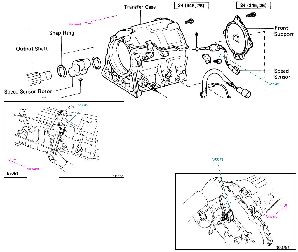
VSS#1 is after the transfer case gears, VSS#2 is before. So VSS#1 is the one used for measuring vehicle speed over the ground (speedometer, cruise, ...), and VSS #2 (I believe) is more for keeping the transmission doing the right thing (because the speed the transmission turns is not directly related to speed over the ground, due to the 2-speed transfer case).
So I'm going to guess you replaced VSS #2, as that sounds like it would have more to do with tranmission codes. If that's the case, you might have had the bad luck to lose #1 at the same time, which took out the speedo (or you might have had some under-truck trauma that damaged the wiring bundle?)
So, first, did you replace the #1 or the #2 sensor?
Feb 10, 2009 | 10:48 AM
#38
Registered User
Joined: Sep 2007
Posts: 8,380
Likes: 871
From: San Francisco East Bay
Given that you lost the code, that suggests the new sensor is good and correctly hooked up at the transmission end. So far so good. It is certainly possible that the speedo itself is bad (I believe it is a tiny stepper motor behind some micro-electronics -- nothing lives forever), but it is more likely that you have a connection problem.
If in your earlier attempts to remedy this you worked on the dash, then it is possible that you loosened a connector somewhere between the transmission and the speedo. Since it looks like the mph signal is getting to the ECM, then the problem is probably closer to the dash.
I've never seen the inside of my dash, so I cannot tell you which connector to try. Also, my (electrical) FSM shows the diagram for the speedo with a drive cable -- not our kind. But I'm 90% sure that the signal wire for the speedo is green/red stripe (because that is what it is at the transmission), so that might help.
Good luck, and let us know what you find!
Feb 11, 2009 | 06:51 AM
#39
Thread Starter
Registered User
Joined: Jun 2008
Posts: 735
Likes: 1
From: Abington, PA
When I ripped the dash apart there are 3 connectors that go onto the gauge cluster. That is why I doubt it's that because none of the wires came out of the harness or looked damaged. The only things left I can think of are the gauge cluster itself and possibly a loose connection somewhere where the sensor plugs connect into the firewall and/or harness (as you already mentioned). I wish there was a local yota person near me that I could swap clusters really quick to eliminate this as the possible issue so I can hunt for the connection gremlin.


