
rgb dash light mod
 Sep 13, 2014 | 11:41 PM
#1
Thread Starter
Registered User
Joined: Sep 2014
Posts: 507
Likes: 8
From: LA CA
rgb dash light mod
Hi all, just wanted to share with you what I've been working on the past couple of days!
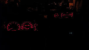
Basically what initiated this project was that a few of my dash bulbs were not making good connection. I'm sure some of you have had the symptom.. one or more of the green 194 bulbs that light the cluster don't always come on unless you tap the clear plastic. Sometimes they stay on, sometimes they don't come on at all.
Well, I got sick of that very quickly. And instead of simply heading to the local auto store to pick up new bulbs or even just cleaning the contacts (because I bet the bulbs were probably fine to begin with), i decided to redo the whole shebang. Having a lot of electrical experience with full color LEDs (both strip continuous as well as addressable leds) I decided I would bring a little love to the dash and have some fun at the same time.
So here is my project...to stuff some old rgb strip lights I had laying around behind the dash and control everything with an arduino (which I also have a lot of experience with). Total cost to do this buying new things would probably be around 50 or 60 bucks, but it didn't cost me a cent!
I took many photos of the first tries, but they ended up sucking so I am omitting them
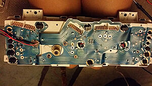
First I tapped into the cluster's 12v supply where the bulbs normally connect. It was easy to trace where the voltage was going on the printed circuit board back behind and then test the connectors on the car with a multimeter for confirmation. I really didn't want to go messing with the clusters wiring harness.
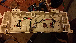
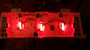
This is the front view with the LEDs wound up, soldered, and mounted where the stock bulbs go (3x 5050 smd rgb led's from a strip x 3). Only red is connected here. This was an exciting moment.
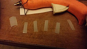
I used a small translucent plastic bottle I had laying around as a diffuser (the LEDs don't emit perfect color in all directions so a diffuser was necessary). In the previous pics these had already been applied with hot glue.
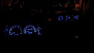
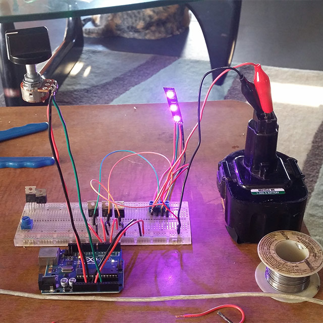
My little test setup with arduino. I powered the leds with 3 n channel mosfets cannibalized from an old project. Those are what turns the arduino's PWM signals into variable voltage for fading the LEDs. As well, the arduino is only on when the lights are on. Everything is powered from the back of the cluster (arduino has negligible power draw anyway). The color can be changed with a potentiometer mounted above the audio head unit area. Turning the pot from left to right the colors go red -> through color wheel -> red -> full white when all the way to the right.

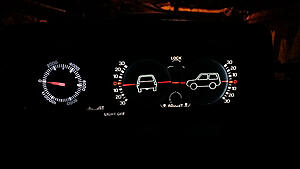
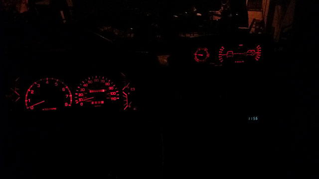
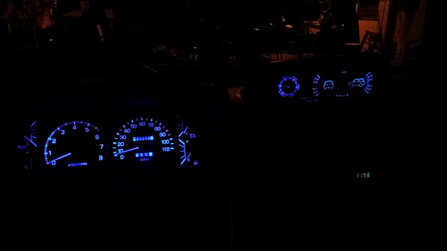
I also did the clinometer, here are some shots of the finished product back in the car! Also, the "Lights off" button on the clinometer still works, I refuse to have non-functioning labeled buttons!
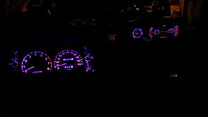
(pink/purple, my personal fav )
)
I am thinking about doing a video, the color changing effect is very graceful. I added a smoothing algorithm that fades it kind of slowly even if you twist the potentiometer very quickly. The color transitions perfectly through the color wheel thanks to a nifty HSV to RGB algorithm I adapted a few years ago. There are a total of 1024 possible colors with this setup, the limit being the resolution of the arduino's analog sense pin for the potentiometer.
This was an incredibly fun project, maybe a bit time consuming. Worth it, though!
I hope you enjoy the read and the pics, hopefully more to come.
Basically what initiated this project was that a few of my dash bulbs were not making good connection. I'm sure some of you have had the symptom.. one or more of the green 194 bulbs that light the cluster don't always come on unless you tap the clear plastic. Sometimes they stay on, sometimes they don't come on at all.
Well, I got sick of that very quickly. And instead of simply heading to the local auto store to pick up new bulbs or even just cleaning the contacts (because I bet the bulbs were probably fine to begin with), i decided to redo the whole shebang. Having a lot of electrical experience with full color LEDs (both strip continuous as well as addressable leds) I decided I would bring a little love to the dash and have some fun at the same time.
So here is my project...to stuff some old rgb strip lights I had laying around behind the dash and control everything with an arduino (which I also have a lot of experience with). Total cost to do this buying new things would probably be around 50 or 60 bucks, but it didn't cost me a cent!
I took many photos of the first tries, but they ended up sucking so I am omitting them
First I tapped into the cluster's 12v supply where the bulbs normally connect. It was easy to trace where the voltage was going on the printed circuit board back behind and then test the connectors on the car with a multimeter for confirmation. I really didn't want to go messing with the clusters wiring harness.

This is the front view with the LEDs wound up, soldered, and mounted where the stock bulbs go (3x 5050 smd rgb led's from a strip x 3). Only red is connected here. This was an exciting moment.


I used a small translucent plastic bottle I had laying around as a diffuser (the LEDs don't emit perfect color in all directions so a diffuser was necessary). In the previous pics these had already been applied with hot glue.

My little test setup with arduino. I powered the leds with 3 n channel mosfets cannibalized from an old project. Those are what turns the arduino's PWM signals into variable voltage for fading the LEDs. As well, the arduino is only on when the lights are on. Everything is powered from the back of the cluster (arduino has negligible power draw anyway). The color can be changed with a potentiometer mounted above the audio head unit area. Turning the pot from left to right the colors go red -> through color wheel -> red -> full white when all the way to the right.
I also did the clinometer, here are some shots of the finished product back in the car! Also, the "Lights off" button on the clinometer still works, I refuse to have non-functioning labeled buttons!
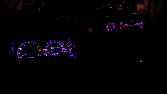
(pink/purple, my personal fav
)
I am thinking about doing a video, the color changing effect is very graceful. I added a smoothing algorithm that fades it kind of slowly even if you twist the potentiometer very quickly. The color transitions perfectly through the color wheel thanks to a nifty HSV to RGB algorithm I adapted a few years ago. There are a total of 1024 possible colors with this setup, the limit being the resolution of the arduino's analog sense pin for the potentiometer.
This was an incredibly fun project, maybe a bit time consuming. Worth it, though!
I hope you enjoy the read and the pics, hopefully more to come.
Last edited by jennygirl; Sep 13, 2014 at 11:45 PM. Reason: fixed img tag
 Hero!!
Sep 14, 2014 | 08:34 AM
Hero!!
Sep 14, 2014 | 08:34 AM
#6
Thread Starter
Registered User
Joined: Sep 2014
Posts: 507
Likes: 8
From: LA CA
Thanks guys!
I don't think I'd have the time or the patience to do this any more than once, so selling them is probably out of the picture... More of a diy thing
I do have some WS2811 pixels laying around, but they have a rather large waterproof housing.
If I had to do it again, I would probably use these (http://www.adafruit.com/products/1655) because I could cram even more LEDs into the same amount of space. It would also be 4X the soldering. The WS2811 stuff is what I usually use for LED projects, I love em!
I haven't used eagle or printed any PCBs, I usually try to find a schematic that works for what I'm trying to do and do everything on a small protoboard. Someday I might get into it though.
Now, if they sold a 194 wedge type LED "bulb" with a WS2811 inside I would have definitely used that... It would look like this but with RGB led's instead of one color.
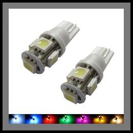
That would fit into the stock housing, and the only task would be connecting 2 extra data wires. I scoured the internet for it but it seems like it doesn't exist yet... THAT would be the thing to get produced and sell. I bet they would sell like hotcakes. Then I would piece together a kit!
Next step is tapping into the engine RPM.. I have been thinking it would be awesome if the color hue was modulated by engine RPM
I don't think I'd have the time or the patience to do this any more than once, so selling them is probably out of the picture... More of a diy thing
I do have some WS2811 pixels laying around, but they have a rather large waterproof housing.
If I had to do it again, I would probably use these (http://www.adafruit.com/products/1655) because I could cram even more LEDs into the same amount of space. It would also be 4X the soldering. The WS2811 stuff is what I usually use for LED projects, I love em!
I haven't used eagle or printed any PCBs, I usually try to find a schematic that works for what I'm trying to do and do everything on a small protoboard. Someday I might get into it though.
Now, if they sold a 194 wedge type LED "bulb" with a WS2811 inside I would have definitely used that... It would look like this but with RGB led's instead of one color.
That would fit into the stock housing, and the only task would be connecting 2 extra data wires. I scoured the internet for it but it seems like it doesn't exist yet... THAT would be the thing to get produced and sell. I bet they would sell like hotcakes. Then I would piece together a kit!
Next step is tapping into the engine RPM.. I have been thinking it would be awesome if the color hue was modulated by engine RPM

Trending Topics
Sep 14, 2014 | 08:45 AM
#8
Thread Starter
Registered User
Joined: Sep 2014
Posts: 507
Likes: 8
From: LA CA
Oh and here is my arduino code for the thread's sake- if anyone else wants to try this out the way I did it.
Here is the schematic (except I have green on pin 3 and blue on pin 6)

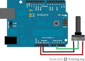
And the schematic for the 10K potentiometer I am using to control color (green to analog pin0 instead)
Code:
// ************** HSV COLOR SETUP ***************

long smoothColor_A[3] = {
  70, 70, 70};

long rgb_A[3];
long rgbval_A, k_A;
float hsv_A[3] = {
  0.0, 1.0, 0.5};
float hsv_delta_A[3] = {
  0.0005, 0.0000, 0.0000};

long bright[3] = {
  256, 256, 256
};


// ***************** ARDUINO PIN SETUP ***********************

int rPin = 5;
int gPin = 3;
int bPin = 6;
int potPin = A0;


// ***************** PROGRAM START ***********************

void setup() {

  pinMode(rPin, OUTPUT);
  pinMode(gPin, OUTPUT);
  pinMode(bPin, OUTPUT);

  rgb_A[0] = 0;
  rgb_A[1] = 0;
  rgb_A[2] = 0;

  for(int i=0; i<27; i++) {
    fadeToColor();
    showColor(smoothColor_A[0], smoothColor_A[1], smoothColor_A[2]);
    delay(15);
  }
}


// ***************** PROGRAM LOOP ***********************

void loop() {

  storeColor();
  fadeToColor();
  showColor(smoothColor_A[0], smoothColor_A[1], smoothColor_A[2]);

  delay(10);
}


// ***************** FUNCTIONS ***********************


void showColor(int r, int g, int b) {

  analogWrite(rPin, r);
  analogWrite(gPin, g);
  analogWrite(bPin, b);

}


void storeColor() {

  int potSetting = analogRead(potPin);

  long curColor = HSV_to_RGB( mapfloat(potSetting, 0, 1023, 0.0, 5.999), 1, 1);

  if(potSetting == 1023) curColor = HSV_to_RGB( 0, 0, 1);

  rgb_A[0] = (curColor & 0x00FF0000) >> 16;
  rgb_A[1] = (curColor & 0x0000FF00) >> 8;
  rgb_A[2] = curColor & 0x000000FF;

}


void fadeToColor() {

  int colorDiff[3] = {
    255, 255, 255              };

  for(int i=0; i<3; i++) {
    colorDiff[i] = rgb_A[i] - smoothColor_A[i];

    smoothColor_A[i] += colorDiff[i]*0.1;
  }

}


long HSV_to_RGB( float h, float s, float v ) {
  /*
   H is given on [0, 6]. S and V are given on [0, 1].
   RGB is returned as a 24-bit long #rrggbb
   */
  int i;
  float m, n, f;

  // not very elegant way of dealing with out of range: return black
  if ((s<0.0) || (s>1.0) || (v<0.0) || (v>1.0)) {
    return 0L;
  }

  if ((h < 0.0) || (h > 6.0)) {
    return long( v * 255 ) + long( v * 255 ) * 256 + long( v * 255 ) * 65536;
  }
  i = floor(h);
  f = h - i;
  if ( !(i&1) ) {
    f = 1 - f; // if i is even
  }
  m = v * (1 - s);
  n = v * (1 - s * f);
  switch (i) {
  case 6:
  case 0: // RETURN_RGB(v, n, m)
    return long(v * 255 ) * 65536 + long( n * 255 ) * 256 + long( m * 255);
  case 1: // RETURN_RGB(n, v, m)
    return long(n * 255 ) * 65536 + long( v * 255 ) * 256 + long( m * 255);
  case 2:  // RETURN_RGB(m, v, n)
    return long(m * 255 ) * 65536 + long( v * 255 ) * 256 + long( n * 255);
  case 3:  // RETURN_RGB(m, n, v)
    return long(m * 255 ) * 65536 + long( n * 255 ) * 256 + long( v * 255);
  case 4:  // RETURN_RGB(n, m, v)
    return long(n * 255 ) * 65536 + long( m * 255 ) * 256 + long( v * 255);
  case 5:  // RETURN_RGB(v, m, n)
    return long(v * 255 ) * 65536 + long( m * 255 ) * 256 + long( n * 255);
  }
}


float mapfloat(float x, float in_min, float in_max, float out_min, float out_max)
{
  return (x - in_min) * (out_max - out_min) / (in_max - in_min) + out_min;
}
Here is the schematic (except I have green on pin 3 and blue on pin 6)
And the schematic for the 10K potentiometer I am using to control color (green to analog pin0 instead)
 Sep 14, 2014 | 09:27 AM
#10
Thread Starter
Registered User
Joined: Sep 2014
Posts: 507
Likes: 8
From: LA CA
Well your enthusiasm is inspiring- I just pulled apart the dash again (while connected) to check voltages to the tach.
These two pins are outputting a voltage directly correlated to engine rpm
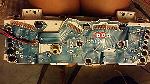
If it goes above 5v I will need to add a few circuit components to keep it in the 0-5v range for the arduino. It's going to take a test drive with multimeter connected to these pins to find out. I'm guessing it's going to go beyond 5v because it was hitting 4.8v sitting in the driveway revving it to about 4k.
I love these older cars, they sure did it right. Nowadays it's all serial data lines running everywhere... Can't hack it worth a dime. Not the case with these 80s yotas
Making a few connectors to run to the center console, will report back later!
Last edited by rworegon; Sep 14, 2014 at 09:29 AM. Reason: Edited out * caught by language censor.
Sep 14, 2014 | 09:31 AM
#11
Thread Starter
Registered User
Joined: Sep 2014
Posts: 507
Likes: 8
From: LA CA
Sep 14, 2014 | 10:11 AM
#12
Registered User
Joined: Jun 2014
Posts: 228
Likes: 1
From: North Alabama
IIRC the leftmost terminal, looking at the back of the tach screws, is the tach input. I had to run the line when I did my cluster swap.
I never put the scope on it to see what the voltages were, but 0-12V would be my guess. A simple resistor divider should clean that up to be within the 3V3 to 5V the atmega considers logical high.
I bet there's a library made for reading tach data, but off the top of my head a loop that times against the micros() return value could get a pretty accurate number. I'm not sure if the tach signal's pulse changes width or just frequency with RPM but if the width changes PulseIn() would probably work too.
 Sep 14, 2014 | 10:46 AM
#14
Thread Starter
Registered User
Joined: Sep 2014
Posts: 507
Likes: 8
From: LA CA
Thanks Jason 
Just went for a drive with leads hooked up to that terminal with voltmeter attached.
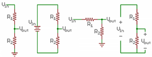
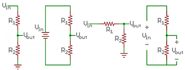
@ 800rpm idle it was ~1.9v and near redline at 5000rpm it was ~5.9v. So it looks like I'll need a little potential divider in there. Just to be on the safe side, I'm going to assume it's a 12v max output from the tach and choose my resistors as such.
My calculator is showing that ~1700 for R1 and ~1200 for R2 should be great to bring 12v down to 5v (4.97v to be exact )
)
Just went for a drive with leads hooked up to that terminal with voltmeter attached.
@ 800rpm idle it was ~1.9v and near redline at 5000rpm it was ~5.9v. So it looks like I'll need a little potential divider in there. Just to be on the safe side, I'm going to assume it's a 12v max output from the tach and choose my resistors as such.
My calculator is showing that ~1700 for R1 and ~1200 for R2 should be great to bring 12v down to 5v (4.97v to be exact
) Sep 14, 2014 | 10:49 AM
#15
Thread Starter
Registered User
Joined: Sep 2014
Posts: 507
Likes: 8
From: LA CA
I am just blown away by how easy that was. I was reading all about frequency to voltage converters and the like, seems that toyota already implemented it!
Looks like a programmable rgb shift light on the cheap is in our near future
Looks like a programmable rgb shift light on the cheap is in our near future
Last edited by jennygirl; Sep 14, 2014 at 10:51 AM.
Sep 14, 2014 | 02:07 PM
#16
Registered User
Joined: Jun 2014
Posts: 228
Likes: 1
From: North Alabama
Yep, I imagine there's an analog voltage somewhere on the tach pcb!

Thread
Thread Starter
Forum
Replies
Last Post
ashersullivan88yota
86-95 Trucks & 4Runners
24
Jan 18, 2022 05:37 PM
Johntom240
General Electrical & Lighting Related Topics
7
Jul 13, 2015 12:18 AM


