
PAIR Removal
 Jun 3, 2012 | 03:22 PM
#41

Registered User

Joined: Sep 2007
Posts: 8,384
Likes: 875
From: San Francisco East Bay

I recommend paying a few cents more and getting socket-head screws (the stock are phillips-head) as they are much easier to install (given the limited space you have).
Jun 3, 2012 | 04:59 PM
#42

Registered User
Joined: Dec 2011
Posts: 93
Likes: 0
This is exactly what I want to do clean up the useless stuff in the engine bay, Hey Mud why did you run the coolant line back to the heater valve. Is that metal line under the plenum just a coolant line I thought the coolant ran through the motor then up through that line. I could see that metal line having corrosion problems and it's difficult to get to for replacement.
Jun 3, 2012 | 06:47 PM
#43
Registered User
Joined: Jan 2007
Posts: 6,106
Likes: 27
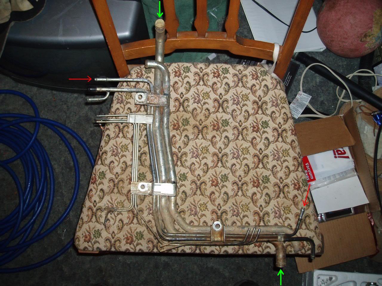
It replaces the metal coolant pipe/line marked by the green arrows in the pic above, the Water By-pass Hose(PNC 16261), and the Inlet A Heater Water Hose(PNC 87245A) in the diagrams below.


So, no, it doesn't run through the motor.
Last edited by MudHippy; Jun 4, 2012 at 06:42 PM.
Jun 6, 2012 | 01:18 PM
#45
Registered User
Joined: Jun 2012
Posts: 27
Likes: 0
From: Pacific NW
Water by-pass pipe
Ok This seems like about the best place to ask my question. I have looked everywhere else, but couldn't find my question answered.
I have a 93 4x4 SR5 extra-cab pickup with a V6 3vze engine. My knock sensor went out and in the process of replacing it, I found a water bi-pass pipe under the intake manifold that has a leak at the inlet at the block. It looks like the only way to remove that pipe assembly is to remove a head. Obviously I do not want to do that unless I really have to. I am thinking of cutting it and then soldering the leak and then splicing it back together with a short piece of hose and hose clamps. Has anyone else ever had this problem? If so, how did you fix it?
I attached a pic of the pipe I am talking about. It is on the left end of the pipe at the flange or whatever you call it, that I believe the leak is at. It also could just be leaking between the flange and the block. There was no gasket in place. I also can't find a gasket for this, but have had a make your own gasket recommended. Any thoughts?
What do you think I should do? Also, does anyone know where to get cheap reman fuel injectors? Mine are very dirty and nasty looking?
BTW, I am also going to be removing my PAIR and EGR too. Thanks MudHippy for the info and pics!
Last edited by mickeydim468; Jun 6, 2012 at 01:22 PM. Reason: Spelling and Name change
Jun 6, 2012 | 03:49 PM
#46
Registered User
Joined: Jan 2007
Posts: 6,106
Likes: 27
Well...it is what it is. But I figure if you get most of the important questions answered in the first 2 pages of a thread...who's gonna bother reading the rest of it anyway?
So...do you have the the 2 bolts(1 bolt & 1 nut actually) holding the pipe to the head and the rear of the block also removed? And you still can't wiggle it out of there? Or you haven't found the lower one(the nut) holding it to the backside of the block yet? Or is the exhaust crossover getting in the way? Because I'm thinking there MUST be a way to do it without removing the heads. But, after taking a quick look at mine just now, it doesn't look to promising with the exhaust crossover still installed.
On the gasket, you could probably get away with some RTV on that one. Or go buy a sheet of gasket material, and cut out a gasket for it.
Don't know on the reman injectors. But I bet you can find some if you
Last edited by MudHippy; Jun 6, 2012 at 03:56 PM.
Jun 6, 2012 | 04:06 PM
#47
Registered User
Joined: Jun 2012
Posts: 27
Likes: 0
From: Pacific NW
Well...it is what it is. But I figure if you get most of the important questions answered in the first 2 pages of a thread...who's gonna bother reading the rest of it anyway?
As for the bolts. Yes I found them all, the crossover is getting in the way or the head is getting in the way. Not sure which would be worse to get at to remove it. It just won't wiggle out. I tried for ten minutes last night and another 1/2 hour today and no good.
It looks like the pipe itself is corroded. Have you ever heard of that happening on these 3vze's?
Jun 6, 2012 | 04:22 PM
#48
Registered User
Joined: Jan 2007
Posts: 6,106
Likes: 27
Removing the crossover would be easiest approach...in theory. Though some folks even remove the heads with it still attached to both. Because it's such a PITA to remove with the heads still on the block. Anyway, if it were me, I'd be removing the crossover.
Seems as though I've heard of a time or two that somebody's had that pipe spring a leak on 'em. And possibly them having to replace it. But it certainly doesn't seem to come up very often. My 88 isn't leaking there, and it looks like that pipe's never been touched since it rolled out of the factory. So, who knows if it ever will?
Seems as though I've heard of a time or two that somebody's had that pipe spring a leak on 'em. And possibly them having to replace it. But it certainly doesn't seem to come up very often. My 88 isn't leaking there, and it looks like that pipe's never been touched since it rolled out of the factory. So, who knows if it ever will?
Jun 6, 2012 | 04:36 PM
#49
Registered User
Joined: Jun 2012
Posts: 27
Likes: 0
From: Pacific NW
Well, leave it to me to find a problem that isn't very common and is a PITA to fix. 
I'll keep y'all updated on what I find. I am going out now to try to fix it.
Oh yeah, I am removing the PAIR and the EGR too. The cat is already gone and a new turbo style muffler is in place.
New knock sensor, (KS pigtail tomorrow), plugs, wires, cap, rotor, 1 injector, (5 more injectors to come), new alternator, power steering pump and battery, have already been done.
Thinking about doing a cold air intake like this one http://www.amazon.com/1988-1995-Toyo...29009&sr=1-228 Or a short ram like this one http://www.amazon.com/Toyota-Pickup-...d_sim_sbs_hi_3 too.
I think I am on the right track huh?
Jun 7, 2012 | 10:26 AM
#51
Registered User
Joined: Jan 2007
Posts: 6,106
Likes: 27
Sounds like a plan to me.
Yeah...I was still kinda wondering what yours does look like. I thought I'd just about seen it all when it comes to these things. Maybe I have?
Jun 7, 2012 | 12:05 PM
#52
Registered User
Joined: Jun 2012
Posts: 27
Likes: 0
From: Pacific NW
I think I did a big boo boo!
When I removed the intake, I didn't make sure to put the #1 piston at TDC. Then to make matters worse, I may have moved one of the cam gears about 2 inches when I had to scoot across the engin to reach a fallen nut. I have not searched this to see if it has been covered, but I think there may even be a worse problem yet. I don't think the timing mark on the gear and the timing mark on the cam line up. What does the cam timing mark look like? I may be looking at the wrong thing. Does anyone have pictures?
Please help!

 Jun 7, 2012 | 01:37 PM
#56
Registered User
Joined: Jan 2007
Posts: 6,106
Likes: 27
1. Remove the spark plug from the #1 cylinder.
2. Put your thumb over the hole, or insert a compression gauge.
3. Turn the crankshaft pulley clockwise until air pressure begins pushing on your thumb, or compression begins building up on the gauge.
4. You've found the compression stroke on the #1 cylinder.
5. Now continue turning the crankshaft pulley clockwise until the timing mark is aligned with the ”0” mark on the No.1 timing belt cover.
6. You've found TDC of the compression stroke on the #1 cylinder.
7. Install distributor as instructed here.
Luckily...I could tell what you meant by what you said.
Last edited by MudHippy; Jun 7, 2012 at 01:51 PM.
Jun 7, 2012 | 02:09 PM
#57
Registered User
Joined: Jun 2012
Posts: 27
Likes: 0
From: Pacific NW
Hey Mud,
Thanks for that, but I am being specific and am using the correct terminology for the problem I am having.
It isn't the distributor. I never removed the destributor. I am talking about the timing belt, and the right side, piston #'s 1, 3, & 5, camshaft gear moving. Is there a mark on the camshaft that denotes TDC for the number one cylinder? Is it viewable without dismantling it from the head? I have the valve cover off and can see a yellow dot painted on the camshaft, but it does not line up with the notch on the gear I mentioned, but it does line up with the mark on the bracket behind the camshaft gear that is also painted yellow.
The camshaft gear has a notch on the outside of the gear near the teeth. Is there any way to install that gear incorrectly? Meaning, can that gear be put on the camshaft in such a way that would make that notch not line up with the cam's TDC mark, when the camshaft is at TDC?
The PO must have done work on this before because the bolt holding that gear on is all boogered up and you can see where they used a puller on it too. That is why I am asking if it could have been installed incorrectly before.
Jun 7, 2012 | 03:22 PM
#58
Registered User
Joined: Jan 2007
Posts: 6,106
Likes: 27
O.k., I can understand what you're saying...NOW.
And, no, it can't. The belt can be installed incorrectly. People do that all the time.
But what I still can't comprehend is what the hell you're trying to achieve here. As in, why is are timing belt and/or the cam gears being messed with? That's not required to get to the knock sensor. How I was supposed to figure out that really was what you were talking about is beyond me. I could only have assumed it meant something else. I mean, why would you be asking that? What does it have to do with removing the intake? Then again, what does removing the distributor have to do with it? Man, what a confusing mess this's become...
Hint: Lost in the dark? Use the FSM to light your way!
Next question: Could we get any further away from the topic of this thread here?
Last edited by MudHippy; Jun 7, 2012 at 03:42 PM.
Jun 7, 2012 | 05:07 PM
#59
Registered User
Joined: Jun 2012
Posts: 27
Likes: 0
From: Pacific NW
I mean, why would you be asking that? What does it have to do with removing the intake?
This is a comedy of errors and I appreciate your help. I have a copy of the FSM, but I don't really understand where to look in it for this problem. This is why I asked here. I tried to look at the replacing the heads and cams and valves, but that assumes you follow the steps and actually put the #1 cylinder on TDC before you take it apart. It didn't tell me to do that in the remove the intake part of the manual I was using to do my first task of getting into the knock sensor. If it did, I missed that step.
I will make my own thread since it has gone off topic. The newb section said it was better to reply to a thread that was already started, so I tried not to start my own.
Sorry!
Mike!
Jun 17, 2012 | 07:45 PM
#60
Registered User
Joined: Jun 2012
Posts: 67
Likes: 0
From: Mesa, AZ
Mudhippy, first I want to thank you for being a great asset to the toyota world because of your vast knowledge. I have read numerous things you have posted since I got my 1988 3vze a month ago that have helped me out tremendously. I am getting ready to remove the pair and egr vacuum line mess and had one question about the electrical connectors on the fender-well. According to the pictures and diagrams they are labeled (AS), (FPU), and (EGR). From looking at your pictures your AS and EGR vacuum lines are removed from the electrical portions on the fender-well. Does this cause any form of check engine light that needs to be tricked? Does the computer look for any feed back from these sensors that you have experienced. I am used to having to reflash or trick modern ECU/ECM's in the newer vehicles to remove egr and emissions systems. Thank you very much.


