When you click on links to various merchants on this site and make a purchase, this can result in this site earning a commission. Affiliate programs and affiliations include, but are not limited to, the eBay Partner Network.
Fuse is good. Relay tests fine. 12v power to relay circuit checks out. No power at horn brass pin and no power to any leads at hazard switch on dash. All four blinkers do work fine. I am certainly no electric pro. I have fixed a ton of things on this poorly maintained beast and these are the only two that need fixing so that i can pass vehicle inspection. I am considering pulling dashboard apart to chase wires. Anything else i should check first?
Last edited by Kungfooyou; Jul 14, 2019 at 06:32 AM.
Providing more details would help here..
"Fuse is good", yeah ive got a whole box of them in my toolbox that are fine also =P
What fuse did you check, and how did you check it. Same for the relay ..
I would start at the horn it self, you should have power on one side of the plug constant and ground when the paddle is depressed in the cab. This tells you if you have a supply or drain issue.
A good rule of thumb with electrical stuff like this is start in the middle and you can rule out half of the problems.
So once you've tested the horn connection, and say it has power but not ground this is " usually " the slipping to plunger surface behind the wheel you can fix this with a brass sleeve (used 22 shell) or a shim on the slip ring. Maybe it's just unplugged at the horn. Do you have power, supply a ground on the other leg and test the actual horn mechanism.
...
Not having any ground or power on the hazard switch tends to make me thing its unplugged..
I don't have that era diagram handy. Your gonna have to dig in and give more details.
Last edited by Co_94_PU; Jul 14, 2019 at 02:01 PM.
It's hard to accept when someone says "fuse is good", we have been lied to before. If you say "I checked for power at the fuse and verified 12 volts on both sides" that would tell us for sure that you checked it properly.
when it comes to "rules of thumb" for electrical diagnostics I don't believe in "start in the middle" I prefer rule #1 to be "check the simple stuff first". Check for power and ground, check the fuse, when it's a light check the bulb. About 98% of the time I have found the issue by then. Rule #2 I agree should be to find a point in the middle of the circuit that is easiest to get to in order to split the possibilities in half, but to do anything past step #1 you need a wiring diagram and either a test light or volt meter, both is better.
I checked both sides of fuse and get 12v. I checked pin #1 on relay and get 12v, i checked relay by hooking positive and negative and it clicks. I even bought a new relay, just in case there was some internal fouling. The brass pin is in great shape, is grounded and makes ample contact with brass ring when steering wheel in installed. I wish too, that my brain could understand wiring. Never had a problem with house wiring, but auto stuff baffles me.
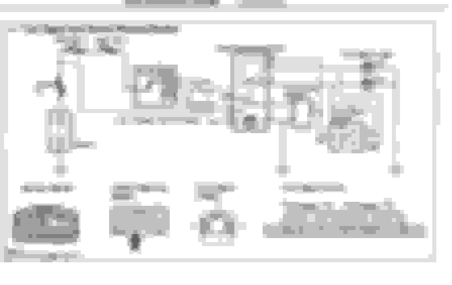
PIN 8 on hazard switch should have power all the time. Since you said there is no power at any pin & fuse shows 12V on both sides, I would say there is break in the wire somewhere between the fuse & the horn/hazard splice in the dash. A quick & dirty fix may be to energize that wire for PIN 8 with constant 12V (fuse protected of course), both horn & hazard may just work again:
Last edited by Paul22RE; Jul 15, 2019 at 12:43 PM.
pull your hazard switch and check pin 8 for 12 volts, see Paul22RE's diagram.
If you get 12 volts there plug the switch in and check for 12 volts at pin 7 when the switch is activated.
you should also get 12 volts at pin 9 and 6 with the switch activated (when everything is working this should be pulsing since it goes through the flasher relay.
You can also check for continuity (good connection) from pin 8 to 7, then from 9 to either 5 or 6, and from 3 to ground.
If your regular turn signals work like you say the flasher is good, and you should have a good connections on the switch from 10 to 7.
Keep in mind the diagram shows you the switch terminals, the wiring harness is a mirror image of that.

 Jul 13, 2019 | 01:31 PM