
3vze Top End rebuild...W/pics...slowly
 May 14, 2005 | 01:53 PM
#181
Contributing Member
Joined: Oct 2004
Posts: 1,817
Likes: 0
From: B'ham, WA
Morph...Looks good can't wait to see it once its back together...I love the power my truck has now and how much better it runs (20 mpg!!)...I like the beefy steering stabilizer, I've got one of those guys too...Good luck
May 15, 2005 | 12:37 PM
#182
Contributing Member
Joined: Jul 2004
Posts: 107
Likes: 0
From: Alden, New York, Suburb of Buffalo, NY
Hi
First off, Morphine, Great job on the rebuild. I don't want to hijack this thread but I need help with my engine that fits in with this thread. What is the best way to removed the toothed gear on the front of the crankshaft? I am asking before I go and ruin something. My thought was to put a gear puller on it along with some penetrating oil. I can see that there is a key way in it. Appreciate the help.
First off, Morphine, Great job on the rebuild. I don't want to hijack this thread but I need help with my engine that fits in with this thread. What is the best way to removed the toothed gear on the front of the crankshaft? I am asking before I go and ruin something. My thought was to put a gear puller on it along with some penetrating oil. I can see that there is a key way in it. Appreciate the help.
May 16, 2005 | 07:36 PM
#183
Thread Starter
Registered User
Joined: Jan 2005
Posts: 571
Likes: 0
From: Moreno Valley, Ca
Timing belt install HELP
OK, so I'm installing my timing belt and the accompaning pulleys, however the marks I originallt made are not lining up. here are some pics. The first one was before the tear down, then followed by how they line up now. Basically I cannot get both the passanger side and driver side cam pulley to line up at the same time.
Before:
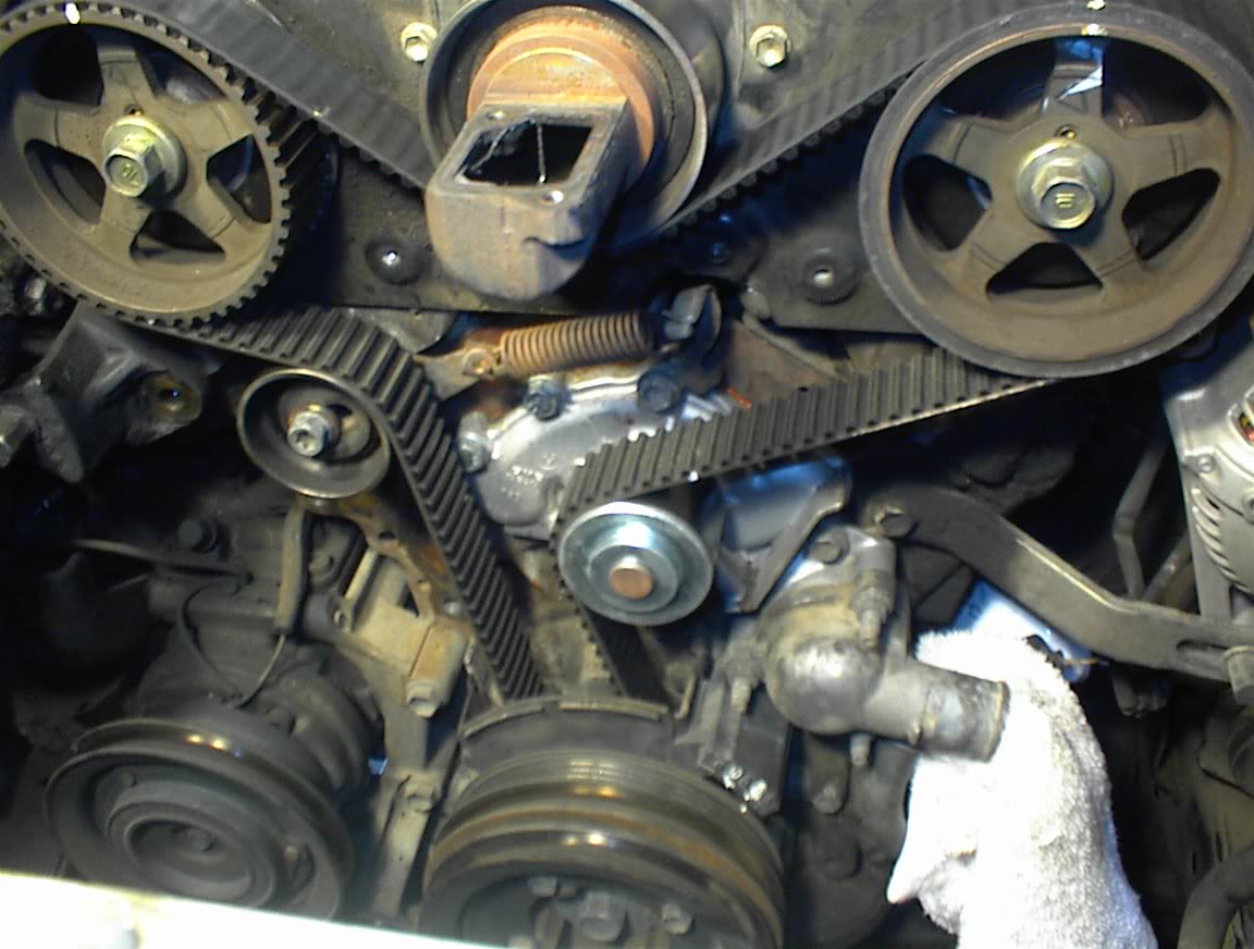
You can see that the "WHITE" mark on both are pointing straight up and down. This happens to align with the pin that the cam pulley fits over. Now here is how it currently is....
Drivers side is ok but the passanger side is about 80degrees off.
This is the drivers side
Passanger side
I searched and didn't find to much. I read and reread the Haynes manual (Garbage) and looked over what Bumpin'Yota sent my way at the beginning. Still I'm lost.
Help, anyone???
-=Morphine=-
Before:
You can see that the "WHITE" mark on both are pointing straight up and down. This happens to align with the pin that the cam pulley fits over. Now here is how it currently is....
Drivers side is ok but the passanger side is about 80degrees off.
This is the drivers side
Passanger side
I searched and didn't find to much. I read and reread the Haynes manual (Garbage) and looked over what Bumpin'Yota sent my way at the beginning. Still I'm lost.
Help, anyone???
-=Morphine=-
May 16, 2005 | 07:59 PM
#184
Thread Starter
Registered User
Joined: Jan 2005
Posts: 571
Likes: 0
From: Moreno Valley, Ca
Big thanks goes out to Silver_Truck
Thanks for helping me out over the phone so quickly. I think I got it. I'll be back in the garage working now.
If you ever make it out my way you have a place to stay man, Thanks again.
-=Morphine=-
Charles
If you ever make it out my way you have a place to stay man, Thanks again.
-=Morphine=-
Charles
May 16, 2005 | 08:03 PM
#185
Registered User
Joined: Aug 2004
Posts: 241
Likes: 0
From: Markle, IN
I just finished replacing my belt the other day, looks to me like your passenger side pulley needs rotated clockwise till the dots match up. Mine moved on me too...just keep track of which direction it goes if it moves & move it back to the mark. For example: if it moves to 10 o'clock (like yours is), move it back to 12 o'clock by turning CW. 
It seems that when the pulley is at the mark it's at the top of the cam lobe, so it wants to rock away from the mark with just a slight move.
Just take yer time....Good luck.
It seems that when the pulley is at the mark it's at the top of the cam lobe, so it wants to rock away from the mark with just a slight move.
Just take yer time....Good luck.
May 17, 2005 | 03:39 AM
#187
Contributing Member
Joined: Nov 2002
Posts: 10,666
Likes: 5
From: Oklahoma State
Originally Posted by Silver_Truck
Let us know how it goes...you've got my number in case you need anything else...Good luck
 May 17, 2005 | 05:39 AM
#189
Thread Starter
Registered User
Joined: Jan 2005
Posts: 571
Likes: 0
From: Moreno Valley, Ca
In Response to my Original question
mt_goat, I'll field this one myself in non technical speak. I was instructed to RTFM, no seriously it was an explenation of the manual.
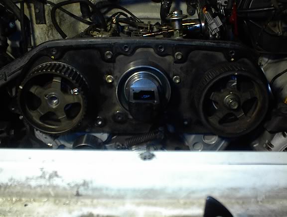
1. Line up the cgroove in the crankshaft sprocket with the mark on the oil pump.
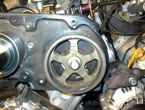
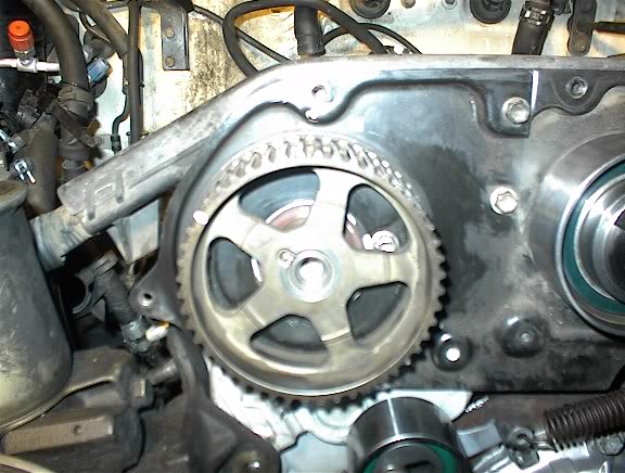
2. Align the camshaft sprocket timing marks with the stationary marks on the rear #3 housing (Back plate). Don't fully install the bolt either.
3. DO NOT INSTALL THE "PIN" ON THE CAM SPROCKET.
4. Install the timing belt over the camshaft sprocket, idler pulleys, fan puley, and crankshaft sprocket.
5.loosen the idler puller boltand pry it to the right as far as possible.Tighten now.
6.Install the tension spring, loosen the bolt again and let the idler tension itself.
7. Install the dampner bolt and verify that everything is lined up with the grooves, marks, etc. (TDC and all aligned).
8. Complete 2 revolutions of the crankshaft sprocket and verify alignment marks.
9. After the alignment is double checked, loosen the cam sprocket bolt and check to see if the "PIN" can be slid in.
***For mine my driverside was lined up but my passanger side was not***
10. Remove the passangerside valve cover.
11. Locate on the cam between the #3 and #5 cylinder lobes the "hexagonal" section.
12. with one hand push the "pin" into place and using the other hand and a wrench, turn the cam using the "hexagonal" section until the pin goes in.
13. Again double check all of your alignment marks and perform another 2 complete revoltiouns.
14. Post on yotatech your results and utmost apprecitation for everyones help ,
Hope this covered it all.
Thanks agian
-=Morphine=-
I was instructed to RTFM, no seriously it was an explenation of the manual.1. Line up the cgroove in the crankshaft sprocket with the mark on the oil pump.
2. Align the camshaft sprocket timing marks with the stationary marks on the rear #3 housing (Back plate). Don't fully install the bolt either.
3. DO NOT INSTALL THE "PIN" ON THE CAM SPROCKET.
4. Install the timing belt over the camshaft sprocket, idler pulleys, fan puley, and crankshaft sprocket.
5.loosen the idler puller boltand pry it to the right as far as possible.Tighten now.
6.Install the tension spring, loosen the bolt again and let the idler tension itself.
7. Install the dampner bolt and verify that everything is lined up with the grooves, marks, etc. (TDC and all aligned).
8. Complete 2 revolutions of the crankshaft sprocket and verify alignment marks.
9. After the alignment is double checked, loosen the cam sprocket bolt and check to see if the "PIN" can be slid in.
***For mine my driverside was lined up but my passanger side was not***
10. Remove the passangerside valve cover.
11. Locate on the cam between the #3 and #5 cylinder lobes the "hexagonal" section.
12. with one hand push the "pin" into place and using the other hand and a wrench, turn the cam using the "hexagonal" section until the pin goes in.
13. Again double check all of your alignment marks and perform another 2 complete revoltiouns.
14. Post on yotatech your results and utmost apprecitation for everyones help ,
Hope this covered it all.
Thanks agian
-=Morphine=-
Last edited by Morphine; May 17, 2005 at 05:41 AM. Reason: grammer
 exactly what he said Mt.Goat, the biggest thing is to nut put the pics in until the sprockets are timed to the crank, the line up the cams with the sprockets and put the pins in
May 17, 2005 | 07:18 AM
exactly what he said Mt.Goat, the biggest thing is to nut put the pics in until the sprockets are timed to the crank, the line up the cams with the sprockets and put the pins in
May 17, 2005 | 07:18 AM
#191

Registered User
Joined: May 2005
Posts: 34
Likes: 0
My tensioner is external, with no spring like shown in the above pics. What's up with that? Did they make different kinds or something? There was never a spring in there at all when I took my motor apart?????????/
May 17, 2005 | 09:51 PM
#195
Thread Starter
Registered User
Joined: Jan 2005
Posts: 571
Likes: 0
From: Moreno Valley, Ca
So Close
I stepped out for a little and helped my mom with her yard work. I also need to get some sleep for work tomorrow. I'm so close That I should have her out of the garage either tomorrow after work or the next day. It's down to just some finishing touches that is taking some time. Connecting the EGR valve and AS reed to the headers. Reconnecting the hoses to the plenum (this will be after the previous item is connected). Re-attach the radiator, fill with fluids, spark plugs and wires and then I crank her.
I'll post more tomorrow and the next day if needed.
-=Morphine=-
I'll post more tomorrow and the next day if needed.
-=Morphine=-
May 24, 2005 | 07:21 AM
#196
Thread Starter
Registered User
Joined: Jan 2005
Posts: 571
Likes: 0
From: Moreno Valley, Ca
She STARTS.....with a minor fuel leak
OK, she starts. Sounds awesome, no exhaust yet just my headers. Now I'm off to troubleshoot a small fuel leak. It's either the #6 cylnider or the drivers side fuel rail.
-=Morphine=-
-=Morphine=-
 May 24, 2005 | 08:33 AM
#198
Contributing Member
Joined: Jan 2005
Posts: 885
Likes: 0
From: Roseville, CA
Originally Posted by Morphine
OK, she starts. Sounds awesome, no exhaust yet just my headers. Now I'm off to troubleshoot a small fuel leak. It's either the #6 cylnider or the drivers side fuel rail.
-=Morphine=-
-=Morphine=-
May 24, 2005 | 08:39 AM
#199
Registered User
Joined: Feb 2003
Posts: 3,689
Likes: 4
From: Sarasota, FL
Originally Posted by Morphine
mt_goat, I'll field this one myself in non technical speak. I was instructed to RTFM, no seriously it was an explenation of the manual.
1. Line up the cgroove in the crankshaft sprocket with the mark on the oil pump.
2. Align the camshaft sprocket timing marks with the stationary marks on the rear #3 housing (Back plate). Don't fully install the bolt either.
3. DO NOT INSTALL THE "PIN" ON THE CAM SPROCKET.
4. Install the timing belt over the camshaft sprocket, idler pulleys, fan puley, and crankshaft sprocket.
5.loosen the idler puller boltand pry it to the right as far as possible.Tighten now.
6.Install the tension spring, loosen the bolt again and let the idler tension itself.
7. Install the dampner bolt and verify that everything is lined up with the grooves, marks, etc. (TDC and all aligned).
8. Complete 2 revolutions of the crankshaft sprocket and verify alignment marks.
9. After the alignment is double checked, loosen the cam sprocket bolt and check to see if the "PIN" can be slid in.
***For mine my driverside was lined up but my passanger side was not***
10. Remove the passangerside valve cover.
11. Locate on the cam between the #3 and #5 cylinder lobes the "hexagonal" section.
12. with one hand push the "pin" into place and using the other hand and a wrench, turn the cam using the "hexagonal" section until the pin goes in.
13. Again double check all of your alignment marks and perform another 2 complete revoltiouns.
14. Post on yotatech your results and utmost apprecitation for everyones help ,
Hope this covered it all.
Thanks agian
-=Morphine=-
I was instructed to RTFM, no seriously it was an explenation of the manual.1. Line up the cgroove in the crankshaft sprocket with the mark on the oil pump.
2. Align the camshaft sprocket timing marks with the stationary marks on the rear #3 housing (Back plate). Don't fully install the bolt either.
3. DO NOT INSTALL THE "PIN" ON THE CAM SPROCKET.
4. Install the timing belt over the camshaft sprocket, idler pulleys, fan puley, and crankshaft sprocket.
5.loosen the idler puller boltand pry it to the right as far as possible.Tighten now.
6.Install the tension spring, loosen the bolt again and let the idler tension itself.
7. Install the dampner bolt and verify that everything is lined up with the grooves, marks, etc. (TDC and all aligned).
8. Complete 2 revolutions of the crankshaft sprocket and verify alignment marks.
9. After the alignment is double checked, loosen the cam sprocket bolt and check to see if the "PIN" can be slid in.
***For mine my driverside was lined up but my passanger side was not***
10. Remove the passangerside valve cover.
11. Locate on the cam between the #3 and #5 cylinder lobes the "hexagonal" section.
12. with one hand push the "pin" into place and using the other hand and a wrench, turn the cam using the "hexagonal" section until the pin goes in.
13. Again double check all of your alignment marks and perform another 2 complete revoltiouns.
14. Post on yotatech your results and utmost apprecitation for everyones help ,
Hope this covered it all.
Thanks agian
-=Morphine=-
I thought that the cam shafts had only one key way for the key that locks the cam pulley to the cam. And you put that key in when you installed the cam pulley. AFter that it should be simply alignment. ??
What is all this talk of putting on the timing belt then installing a key??
(When I did my timing belt/waterpump/tensioner/idler/thermostat replacement, I didnt pull the cam pulleys...I figured they would be exactly like the crankshaft's keyed shaft...)
Last edited by Bumpin' Yota; May 24, 2005 at 08:46 AM.
May 24, 2005 | 08:51 AM
#200
Contributing Member
Joined: Oct 2004
Posts: 1,817
Likes: 0
From: B'ham, WA
The cams and the pulley both have only one hole for the pin...but generally after you've done your heads the cams aren't at #1 TDC so you have to time the cam pulleys back to #1 TDC with the crank pulley then rotate the cams to #1 TDC so they line up with the pulleys and the key /pin slides right in...hope that clears things up


