
Replacing Tie Rods/ Idler Arm 2nd gen 4runner/Pickup
 May 11, 2014 | 05:33 PM
#1
Thread Starter
Registered User


Joined: Oct 2011
Posts: 97
Likes: 22
From: Fullerton, CA
Replacing Tie Rods/ Idler Arm 2nd gen 4runner/Pickup
Edit September 2022: Links to FSM Files: https://drive.google.com/drive/folde...qkjbmTQ_fYY2mY
I still need to go back through this post and update with torque specs instead of referencing the PDF.
/Edit.
Heads up: This is my first attempt at a tech write up so bear with me... I may or may not be very good at this. I also in no way am a professional or intend to sound like a professional. This is simply what worked for me and hopefully what may help you. I, nor Yotatech, bear any responsibility for any damage, death, etc. Now let's begin.
I have seen a lot of useful information around yotatech regarding tie rods, however I have not seen any actual write ups on the subject.
I want to try to help anyone who wants to save some money or learn something new; or if there are simply some unanswered questions floating around.
This is the first time I have replaced the tie rods on my own, but it was a rather straightforward process, and my steering is smoother and tighter now than before.
If you are going to replace your tie rods, I would recommend doing the idler arm, pit man arm, and steering stabilizer as well. (Why not, right)
I have yet to replace my pit man arm, was on back order.
EDIT: I have now replaced the pitman arm, however, I could NOT get it off. It actually BENT my puller, so I took it to Midas to have them replace it for me. Just a heads up... It was stock, and pressed on there so hard I coudn't do it myself. And I hate paying people to do what I could've done...
Parts required: (Part Numbers added September 2022)
Inner Tie Rods (2) -$17.99 a piece from Autozone; Duralast Tie Rod End ES3192
Outer Tie Rods (2)- $15.99 a piece from Autozone; Duralast Tie Rod End ES2376
Idler Arm (1)- $45.99; Duralast Idler Arm FA5040
Pit Man Arm (1)- $64.99; Rare Parts Pitman Arm 21044 (Not the one I purchased, but is all the website is showing)
OME Steering Stabilizer (1)- was about $100 shipped from Rocky Road Outfitters
Cotter Pins (6)- around $3.00 for an assorted pack
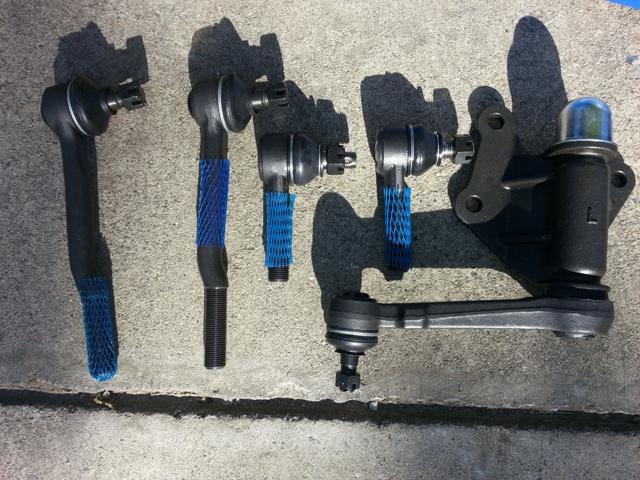
New parts:
Tools required:
Jack and stands
Pliers
Basic metric socket set (plus a big one for pit man arm nut)
Breaker bar (for idler arm bolts)
Torque wrench
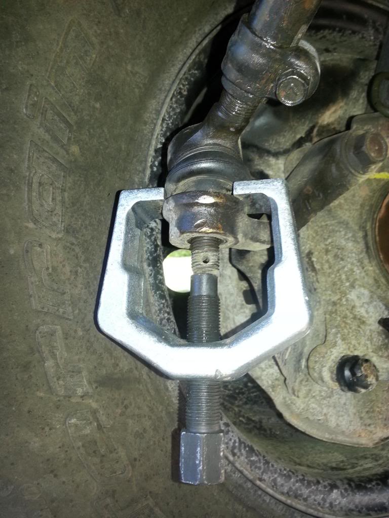
Ball joint puller (looks like this) REQUIRED or you'll have a bad time
*Edit September 2022: Found FSM and created link. Exploded View is titled "SR-67 Steering Linkage Components"*
Link to PDF of exploded steering components: https://drive.google.com/drive/folde...mY?usp=sharing
1) Safely jack up front wheels and secure in place with stands. Remove skid plate and set aside.
2) Remove old cotter pins. Break bolts loose; tie rods to knuckle, tie rods to relay rod, idler arm to relay rod, idler arm to frame (3 bolts with nuts on opposite side), pit man arm to relay rod, steering damper to relay rod, steering damper to frame,
3) Use the ball joint/ tie rod puller as shown above to remove all desired components. Move steering wheel back and forth as necessary for better accessibility to parts.
You will hear a LOUD pop when they come loose.
I wear goggles and gloves whenever working with large torques; it's a mix between being smart and scared.
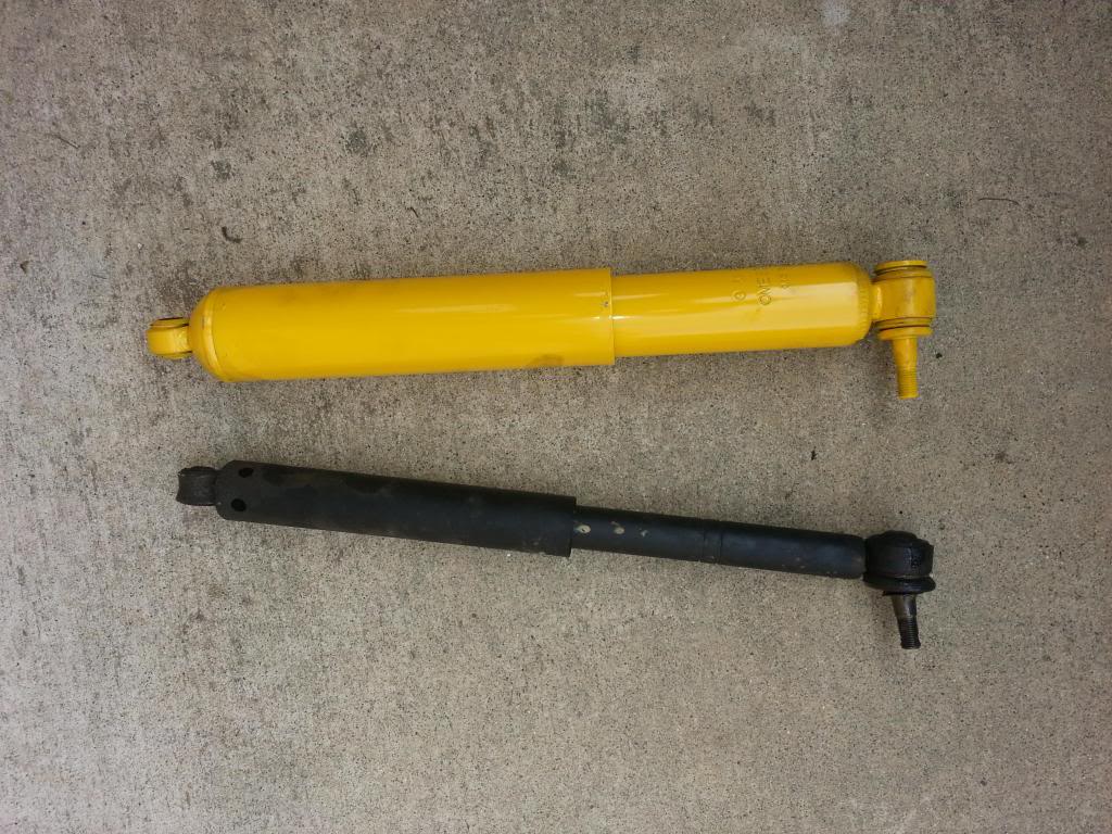
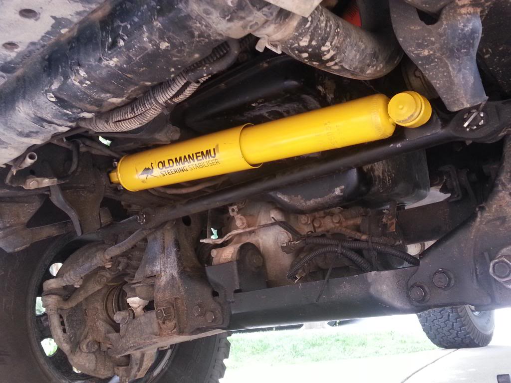
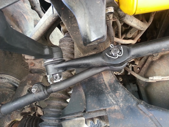
4) The steering damper is easily replaced. Follow PDF as necessary.
Picture from last week when I did only the damper:
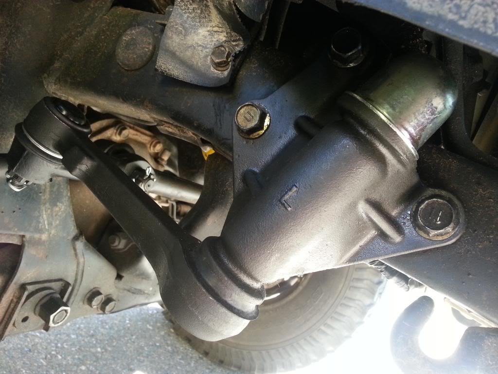
5) Remove and Replace Idler Arm; Idler Arm Bracket to Frame Torque Specs: 105 ft-lb, (142 Nm)
6) Pit Man Arm- (Like I mentioned, I've yet to do mine, waiting on the part) UPDATE: See Above, Had Midas do it as it bent my puller.
Use puller to remove from relay rod.
Remove Pit man arm nut- This will most likely require a breaker bar.
Use puller to remove pit man arm- take note of orientation and splines on the shaft.
Press new arm onto shaft, torque to PDF spec (130 ft-lb, 177 Nm).
7) Tie Rods: Compare lengths and orientation of Tie Rods
Before loosening tie rod clamps, make note of length on either side. You will need to be as accurate as possible before/ after.
(sorry no pic, thought I took one) (refer to PDF, page SR-69, has pretty good explanation)
Replace inner/ outer tie rods, adjust to 90* for proper fitment as when they were taken off, and tighten clamps.
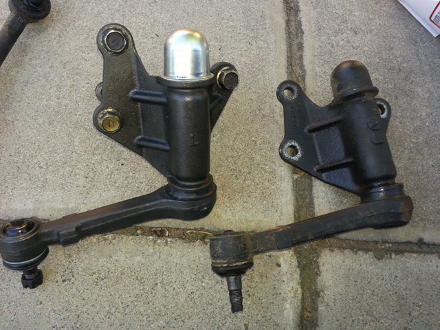
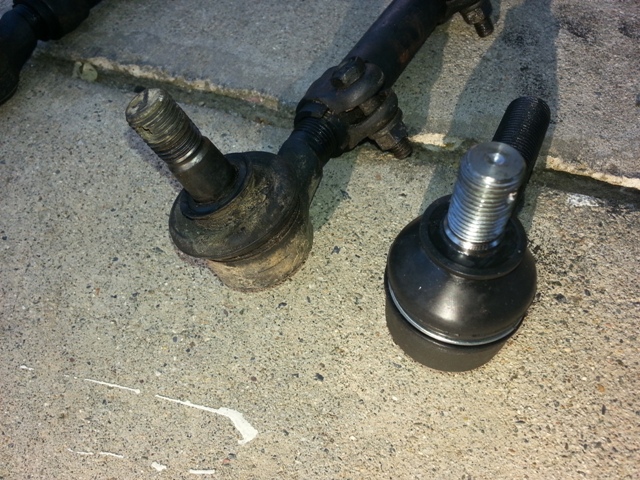
Here's just a look at how worn mine were compared to new:
8) Connect all new components to proper alignment, hand tighten new castle nuts for all steering linkage.
Torque to correct specifications - PDF (will update but at work and lunch is over, Sep 22)
Install cotter pins wherever there is a castle nut. (I'm not very good at this)
9) Eyeball your tires for toe in/ out. You can kind of adjust this by loosening tie rod clamp nuts, and rotating, this will adjust the tie rods and in turn move the wheels in or out.
Make sure the steering wheel is centered while you do this.
Re tighten clamp nuts.
10) Double Check to make sure everything is installed, torqued, cotter pinned, and ready to go.
11) Lower truck, reinstall skid plate, clean up
Drive the truck around and listen for anything unusual
Love your new steering linkage
---Get An Alignment- The toe will be off, and the wheels may no longer be centered with the steering will.
Please leave feedback!
If you found this useful, or if you think I left out something important,
please let me know. Feel free to criticize, just don't be mean.
I still need to go back through this post and update with torque specs instead of referencing the PDF.
/Edit.
Heads up: This is my first attempt at a tech write up so bear with me... I may or may not be very good at this. I also in no way am a professional or intend to sound like a professional. This is simply what worked for me and hopefully what may help you. I, nor Yotatech, bear any responsibility for any damage, death, etc. Now let's begin.
I have seen a lot of useful information around yotatech regarding tie rods, however I have not seen any actual write ups on the subject.
I want to try to help anyone who wants to save some money or learn something new; or if there are simply some unanswered questions floating around.
This is the first time I have replaced the tie rods on my own, but it was a rather straightforward process, and my steering is smoother and tighter now than before.
If you are going to replace your tie rods, I would recommend doing the idler arm, pit man arm, and steering stabilizer as well. (Why not, right)
I have yet to replace my pit man arm, was on back order.
EDIT: I have now replaced the pitman arm, however, I could NOT get it off. It actually BENT my puller, so I took it to Midas to have them replace it for me. Just a heads up... It was stock, and pressed on there so hard I coudn't do it myself. And I hate paying people to do what I could've done...
Parts required: (Part Numbers added September 2022)
Inner Tie Rods (2) -$17.99 a piece from Autozone; Duralast Tie Rod End ES3192
Outer Tie Rods (2)- $15.99 a piece from Autozone; Duralast Tie Rod End ES2376
Idler Arm (1)- $45.99; Duralast Idler Arm FA5040
Pit Man Arm (1)- $64.99; Rare Parts Pitman Arm 21044 (Not the one I purchased, but is all the website is showing)
OME Steering Stabilizer (1)- was about $100 shipped from Rocky Road Outfitters
Cotter Pins (6)- around $3.00 for an assorted pack
New parts:


Tools required:
Jack and stands
Pliers
Basic metric socket set (plus a big one for pit man arm nut)
Breaker bar (for idler arm bolts)
Torque wrench
Ball joint puller (looks like this) REQUIRED or you'll have a bad time

*Edit September 2022: Found FSM and created link. Exploded View is titled "SR-67 Steering Linkage Components"*
Link to PDF of exploded steering components: https://drive.google.com/drive/folde...mY?usp=sharing
1) Safely jack up front wheels and secure in place with stands. Remove skid plate and set aside.
2) Remove old cotter pins. Break bolts loose; tie rods to knuckle, tie rods to relay rod, idler arm to relay rod, idler arm to frame (3 bolts with nuts on opposite side), pit man arm to relay rod, steering damper to relay rod, steering damper to frame,
3) Use the ball joint/ tie rod puller as shown above to remove all desired components. Move steering wheel back and forth as necessary for better accessibility to parts.
You will hear a LOUD pop when they come loose.
I wear goggles and gloves whenever working with large torques; it's a mix between being smart and scared.
4) The steering damper is easily replaced. Follow PDF as necessary.
Picture from last week when I did only the damper:

5) Remove and Replace Idler Arm; Idler Arm Bracket to Frame Torque Specs: 105 ft-lb, (142 Nm)


6) Pit Man Arm- (Like I mentioned, I've yet to do mine, waiting on the part) UPDATE: See Above, Had Midas do it as it bent my puller.
Use puller to remove from relay rod.
Remove Pit man arm nut- This will most likely require a breaker bar.
Use puller to remove pit man arm- take note of orientation and splines on the shaft.
Press new arm onto shaft, torque to PDF spec (130 ft-lb, 177 Nm).
7) Tie Rods: Compare lengths and orientation of Tie Rods
Before loosening tie rod clamps, make note of length on either side. You will need to be as accurate as possible before/ after.
(sorry no pic, thought I took one) (refer to PDF, page SR-69, has pretty good explanation)
Replace inner/ outer tie rods, adjust to 90* for proper fitment as when they were taken off, and tighten clamps.
Here's just a look at how worn mine were compared to new:

8) Connect all new components to proper alignment, hand tighten new castle nuts for all steering linkage.
Torque to correct specifications - PDF (will update but at work and lunch is over, Sep 22)
Install cotter pins wherever there is a castle nut. (I'm not very good at this)

9) Eyeball your tires for toe in/ out. You can kind of adjust this by loosening tie rod clamp nuts, and rotating, this will adjust the tie rods and in turn move the wheels in or out.
Make sure the steering wheel is centered while you do this.
Re tighten clamp nuts.
10) Double Check to make sure everything is installed, torqued, cotter pinned, and ready to go.
11) Lower truck, reinstall skid plate, clean up
Drive the truck around and listen for anything unusual
Love your new steering linkage
---Get An Alignment- The toe will be off, and the wheels may no longer be centered with the steering will.
Please leave feedback!
If you found this useful, or if you think I left out something important,
please let me know. Feel free to criticize, just don't be mean.
Last edited by ztbailey1; Sep 13, 2022 at 12:54 PM. Reason: link
Dec 19, 2015 | 01:01 PM
#3

Registered User

Joined: Sep 2007
Posts: 8,383
Likes: 873
From: San Francisco East Bay
Great job!
Next time you do a write-up (and I hope you will), consider including the part numbers of the parts you used, and list the torques. We can all get the torques from the FSM, but you already looked them up so go ahead and write them down.
Next time you do a write-up (and I hope you will), consider including the part numbers of the parts you used, and list the torques. We can all get the torques from the FSM, but you already looked them up so go ahead and write them down.
Dec 20, 2015 | 09:20 AM
#4
Great write up and sure it made a big difference on the steering. One other thing I like to change out that helps take some of the vibrations is to replace the rag joint. It is located between the steering shaft and gear box when doing the front end. Your write up will help someone new to wrenching and make it less stressful for them.
Dec 20, 2015 | 10:52 AM
#5

Registered User
Joined: Nov 2015
Posts: 17
Likes: 0
I'll try to update this thread and take some pictures as I am doing the same job in about a week and we can make this a good front end steering thread.
I will be replacing the:
Inner Tie Rods
Outer Tie Rods
Adjusting Sleeves
Pitman Arm
Idler Arm
Both CV Axles
Replace and Pack Wheel Bearings
The reason I believe the Torques were not added is because you can basically just tighten them until you can get the cotter pin through the bolt. But I will also add the torque specifications for a piece of mind when I update this.
Last edited by 93ToyotaPickup/; Dec 20, 2015 at 01:41 PM.
Dec 21, 2015 | 11:49 AM
#6

Registered User
Joined: Dec 2015
Posts: 5
Likes: 0
93Toyotapickup, I'm not sure if you've done this job before but I just did the exact same thing 2 weeks ago minus the wheel bearings. I started with the CV axle by unbolting it from the dif (very helpful to have someone step on the breaks for you to keep it from spinning. From there I spent nearly half an hour and nearly all my energy to try wrestling the CV out. I tried turning the wheels and still could not get enough room to wiggle it out. Then the lights finally turned on and I realized this would be a lot easier with the hub off.
So...after unbolting the CV axle and snap ring holding it to the hub, move directly removing the brake caliper and ball joints. The CV will do whatever you want once the hub is out of the way.
Same with installation, with hub sitll removed slide the CV onto the dif and hold it there with 3 bolts just slightly threaded on. Then slide on the hub after greasing the axle splines.
Dec 21, 2015 | 01:08 PM
#7
Registered User
Joined: Sep 2007
Posts: 8,383
Likes: 873
From: San Francisco East Bay
350xrider -
If you had come here 3 weeks ago, you would have saved yourself a lot of work and frustration.
The half-shafts (the CVs are the joints at wheel end) will NOT come out if the wheels are dangling, which they are if you have the frame up on jack stands. The angle is wrong. You need to compress the suspension as though the truck were sitting on the wheels. (I use a small jack under the hub; lift until the load starts to come off the nearest jack stand.) Then the half-shafts will come out easily.
You may get to do this job again (the CV joint boots wear and leak grease, for instance); you can try it then.
Trending Topics
Dec 21, 2015 | 03:22 PM
#8
Registered User
Joined: Nov 2015
Posts: 17
Likes: 0
Thanks for the info 350xrider and scope103
I have not done this job before so all the helpful information will really help with the process of it. So what you are saying is in order to get the half axles out i need to put a jack stand under that side to compress it? That makes sense. That will save me a lot of time trying get those in and out. Any tips with help me a ton. Thanks guys!
I have not done this job before so all the helpful information will really help with the process of it. So what you are saying is in order to get the half axles out i need to put a jack stand under that side to compress it? That makes sense. That will save me a lot of time trying get those in and out. Any tips with help me a ton. Thanks guys!
Dec 21, 2015 | 03:36 PM
#9
Registered User
Joined: Sep 2007
Posts: 8,383
Likes: 873
From: San Francisco East Bay
In theory, you could remove the half-shafts without jacking the truck at all. But there's not much room to get in there, and if you have alloy wheels you may not be able to remove the cone washers with the wheels still on. Doing it that way is mostly a "demonstration."
Also "in theory" you could jack the truck on the lower control arm instead of the frame. That might not work (your jack won't be as far out as the ball joints, so it might not have enough leverage to compress the suspension). You also risk denting the lower control arm; it's not really a jacking point.
But you get the idea.
Last edited by scope103; Dec 21, 2015 at 03:38 PM.
Dec 21, 2015 | 03:49 PM
#10
Registered User
Joined: Nov 2015
Posts: 17
Likes: 0
Ya what i ment was put a jack stand on the frame and another smaller one on the side to compress. But i guess just using the jack itself would be much easier. Thanks for all the help. If i didnt know about that I would have probably been stuck out in the garage for a couple hours trying to get the half axles out haha. Ill be doing all this work starting either on saturday on next week on monday. Thanks guys
Nov 26, 2020 | 10:35 AM
#13
Thread Starter
Registered User
Joined: Oct 2011
Posts: 97
Likes: 22
From: Fullerton, CA
Hey guys, not sure if anyone has used this thread as a reference or not over the last few years, but I've decided to start being more active on Yotatech again, and will post some edits with torque specs and part numbers as soon as I get home. Visiting my grandparents in Arizona right now and don't have access to the info I have written down at home.
Oh and Happy Thanksgiving!
*FINALLY got around to doing some updates September 2022*
Oh and Happy Thanksgiving!
*FINALLY got around to doing some updates September 2022*
Last edited by ztbailey1; Sep 13, 2022 at 12:56 PM.

Thread
Thread Starter
Forum
Replies
Last Post


