
dropzone's notebook of ideas, links, mods, misc BS
 Sep 26, 2011 | 11:08 AM
#101
Toyota Truck Wheel Base information
**From the Pirate FAQ 2.0**
*From the factory manuals:
1979-83 short bed 101.77 *
1979-83 long bed 110.24 *
1984-89 4Runner 102.95 *
1984-88 xtra cab 112.20 *
1984-88 single cab short bed 102.95 *
1984-88 single cab long bed 112.20 *
1984-88 double cab real short bed 112.20 *
1990-91 4Runner, 2 door 103.3
1990-95 4Runner, 4 door 103.3
1989-95 short bed 103.3
1989-95 long bed 122.5
1989-95 xtra cab 122.5
1995.5-04 Tacoma 105.3 and 121.9
1996-92 4Runner (taco based) 105.3
1st Gen truck bed dimensions:
Last edited by dropzone; Nov 19, 2011 at 06:12 PM.
Apr 30, 2012 | 08:17 AM
#102
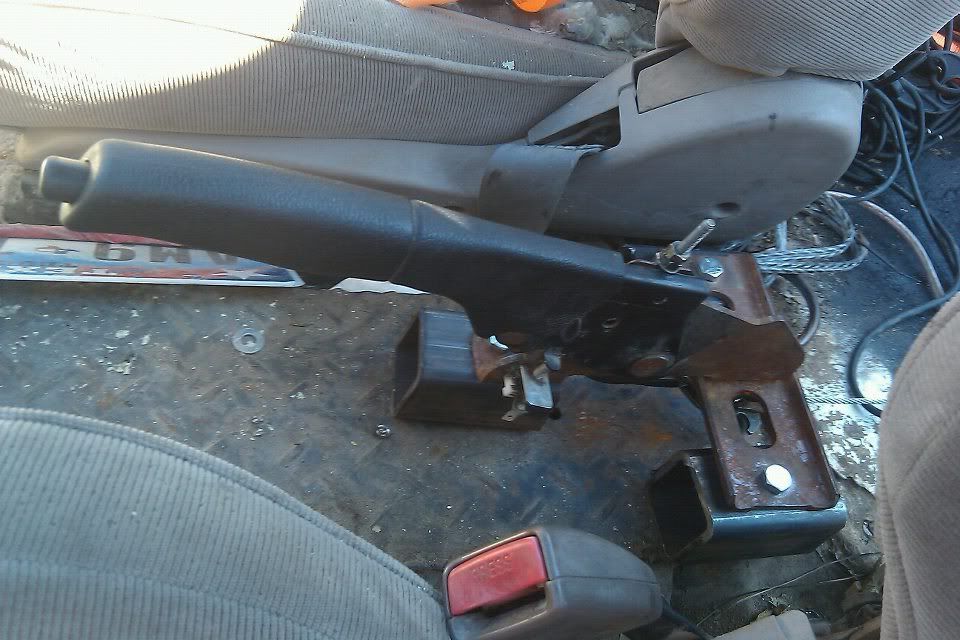
tunnel mounted E-Brake
An alternate e brake idea
Ok, so I think I have some tech here. I had trouble getting my allpro ebrake kit adjusted well and ended up frying out the whole brake pad. With inspection due this month I finally got around to trying to fix it.
Sence the cable was broken on the original ebrake handle I decided to go with a center pull set up. I used the brake leaver out of a isuzu rodeo. I used some 2x2 square steel bolted down to the floor to get the clearance for the cable to go under.
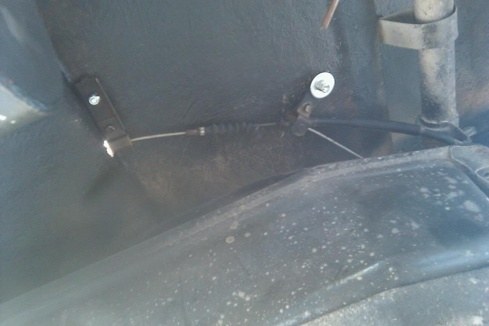
Then I used the end of where the ebrake cable originally hooked up to the axle and ran it through the floor board and to the ebrake handle set up from the rodeo. I drilled a hole in the original ebrake link cable on the rodeo set up to put hook up where the ebrake cable originally hooked up to axle drum.
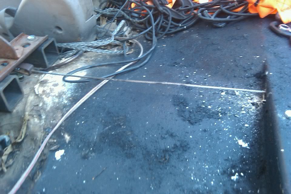
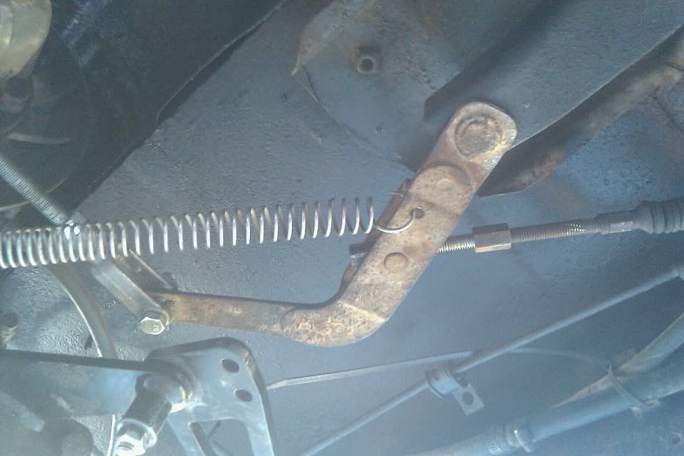
And how its routed under the truck.
Next you hook up the link from the allpro ebrake that go to the lever arm and attach it to the orginal lever arm on the bottom of the toyota like this.
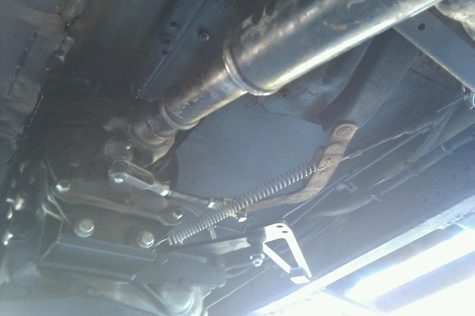
And put the return spring into the new lever arm to return the brake to open.
And thats basically the set up. Im going to get some square tube to cover up the cable that runs on the floor but so far it looks like it will work like a charm. I havent been able to fully test it out because Im waiting for the new caliper from allpro as well as a new rear tcase output seal. (ordered up a marlin ecoseal, figured I might as well go with a quality part). Along with that Im also waiting on the brake upgrade kit I ordered from Davez offroad. For $200 for v6 ifs calipers, pads, and fj rotors is too good of a price to pass up. All in all I paid $15 for the ebrake handle from the pick-n-pull and everything else was laying around. Next I will probably try and get my old rodeos center consel to work in the toyota too.
Sence the cable was broken on the original ebrake handle I decided to go with a center pull set up. I used the brake leaver out of a isuzu rodeo. I used some 2x2 square steel bolted down to the floor to get the clearance for the cable to go under.
Then I used the end of where the ebrake cable originally hooked up to the axle and ran it through the floor board and to the ebrake handle set up from the rodeo. I drilled a hole in the original ebrake link cable on the rodeo set up to put hook up where the ebrake cable originally hooked up to axle drum.
And how its routed under the truck.
Next you hook up the link from the allpro ebrake that go to the lever arm and attach it to the orginal lever arm on the bottom of the toyota like this.
And put the return spring into the new lever arm to return the brake to open.
And thats basically the set up. Im going to get some square tube to cover up the cable that runs on the floor but so far it looks like it will work like a charm. I havent been able to fully test it out because Im waiting for the new caliper from allpro as well as a new rear tcase output seal. (ordered up a marlin ecoseal, figured I might as well go with a quality part). Along with that Im also waiting on the brake upgrade kit I ordered from Davez offroad. For $200 for v6 ifs calipers, pads, and fj rotors is too good of a price to pass up. All in all I paid $15 for the ebrake handle from the pick-n-pull and everything else was laying around. Next I will probably try and get my old rodeos center consel to work in the toyota too.
May 9, 2012 | 10:32 PM
#103
half Door Latch/Handle
half door latch-one approach:
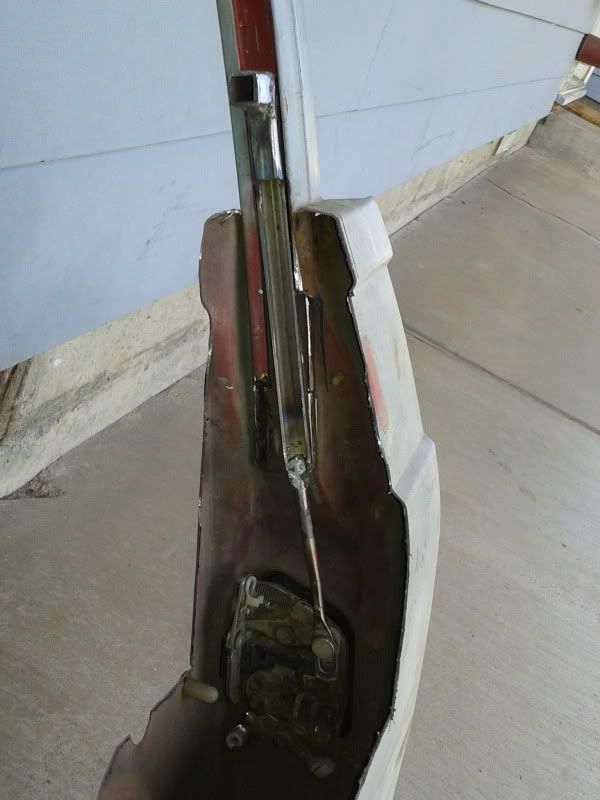
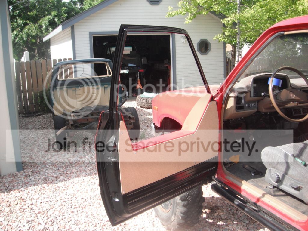
I totally removed the door handle, welded the bar from the handle to a piece of 1/2" tube and brought it up through the window channel:
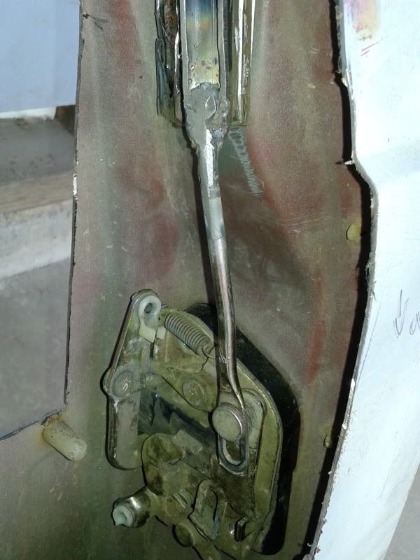
i wish I had seen this approach before I made my latch release...this is stupid simple.
I will post a pic of another latch so you can see how this one would work.
(from this thread on Marlin http://board.marlincrawler.com/index...515#msg1013515)
I totally removed the door handle, welded the bar from the handle to a piece of 1/2" tube and brought it up through the window channel:
i wish I had seen this approach before I made my latch release...this is stupid simple.
I will post a pic of another latch so you can see how this one would work.
(from this thread on Marlin http://board.marlincrawler.com/index...515#msg1013515)
Wanted to share my really simple door release for half doors. It's just a piece of 550 cord tied in a loop to the spring-loaded lever that is normally attached to the inside door release. Passed it through the half door and used a grommet to clean it up. Best part is no rattles!
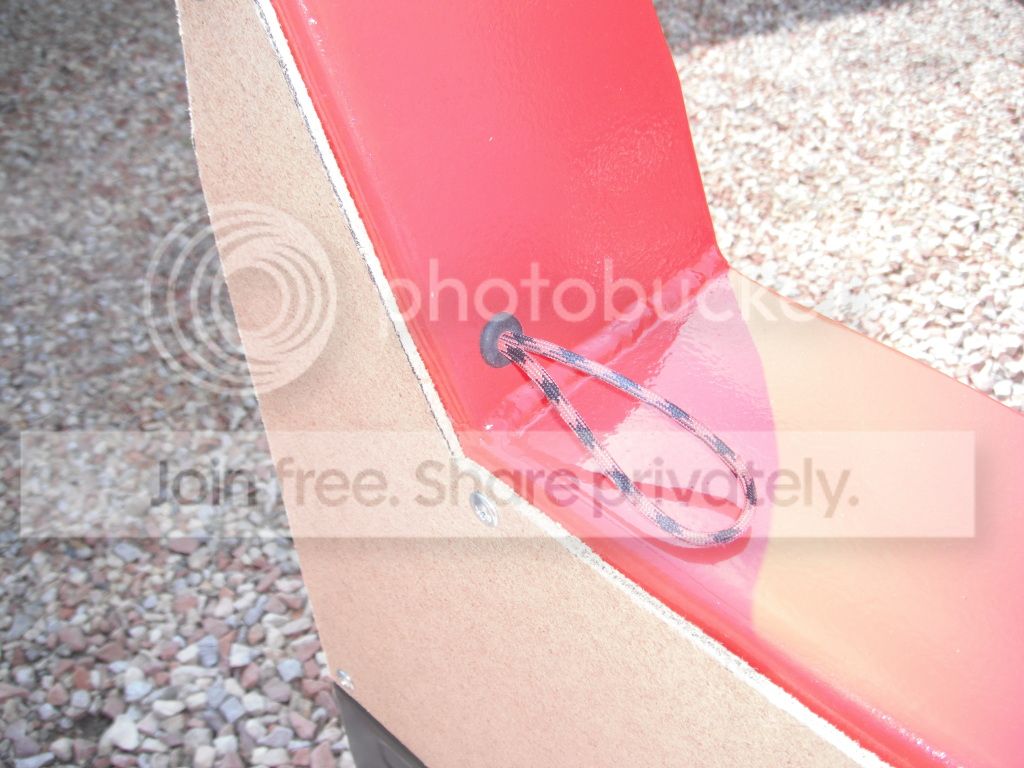
It does not get in the way at all and is very easy to use.
It does not get in the way at all and is very easy to use.
Last edited by dropzone; Jun 14, 2012 at 05:26 AM.
Jun 14, 2012 | 05:08 AM
#105
I have some info on head/block compatibility differents but need to find the thumb drive i stored the pics on..should have uploaded them straight to photobucket
 Jun 14, 2012 | 05:10 AM
#106
Propane Tank Mounts/Internals
the pics below borrowed from this thread:
http://www.pirate4x4.com/forum/showthread.php?t=1071545
will post more info on mounts later on..
http://www.pirate4x4.com/forum/showthread.php?t=1071545
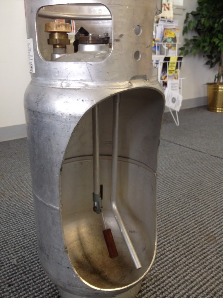
It is a liquid feed tank and must be mounted in the correct position: horizontally with the indexing holes on the bottom, or vertically with the valve at the top of the tank.
There is actually 2 reasons it must be mounted with the holes down if it is sideways, one is so the tube will pick up liquid but also the pressure release is opposite the holes and needs to be at the top so it vents vapor if the tank is over filled or gets too hot. You don't want liquid spraying in the back of your rig. 1 gallon of liquid propane boils to 275 gallons of vapor...
 Jun 16, 2012 | 06:14 PM
#109
Rebuilding Aisin Manual Hubs
how to rebuild hubs:
http://www.se4rj.com/forum/showthread.php?t=293
all of this info is from Waskillywabbit's AIsin hub rebuilt how to in the link above:
Toyota Aisin manual hubs are a nice upgrade over ADD and auto hubs found on various Toyota 4x4s, 79-95. During this time period you have solid front axles (SFA) on pickups and 4Runners, and independent front suspensions (IFS) on the same. I am talking strictly about these years and models. There are numerous other Aisin manual hubs and many of those parts are useful as well.
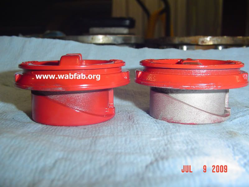
SFA on the left, IFS on the right in the pictures
The red dials are interchangeable on various types of Aisins, with one noticeable difference that disinguishes the SFA dial on the left, it has a raised and curved "handle" for easier gripping. Since the dials are interechangeable do not always assume what kind of hub you have without looking at several factors that distinguish the two, as mentioned below. I have purchased quite a few Aisins that folks thought were IFS and actually turned out to be SFA, thus I got them on the cheap and was pleasantly surprised.
The black face is the same on the SFA and IFS and are easily interchangeable as are the hub dial o-ring, and the little ball and spring located in the little hole on the dials. If you decide to clean your Aisins and disassemble them, be careful not to lose the little ball and spring. The number one thing missing on Aisins I purchase are these items, thus the reason I found a source for them so I could replace them.
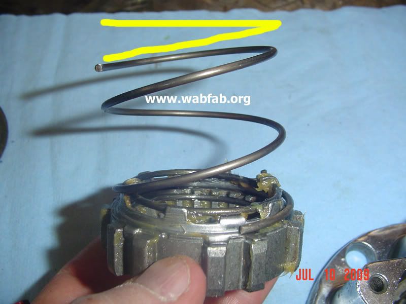
The big springs are all the same, but you must install them correctly. Here is the difference.
This is flat side up.
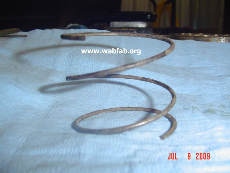
This is flat side down.
You want to install the spring flat side down towards the clutch (see next pic).
The clutch spring mechanism is interchangeable but the clutches themselves are different, and different enough that you can't put the SFA one in the IFS, but it will work vice versa, due to the height difference. I don't swap them myself as it can cause issues of fitment in certain instances. SFA is on the left and taller than the IFS one on the right.
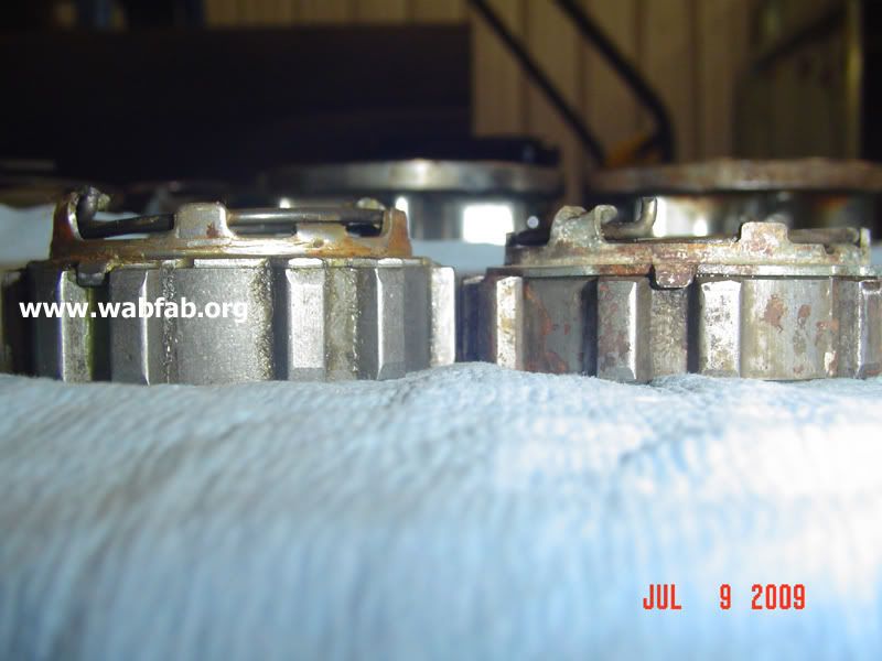
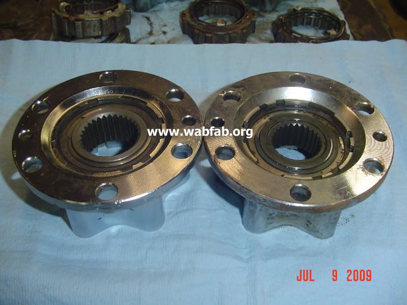
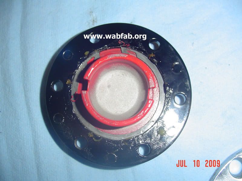
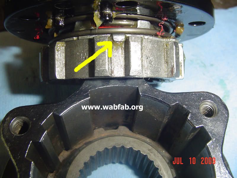
The biggest difference is the hub gear, SFA is 30 spline and the IFS is 26 spline, yep I counted them. While interchangeable in the hub assembly, they are not usable if swapped due to clearances and fitments. Examing the hub from the backside of the flange and seeing the hub gear splines and the difference in the recession on the face of the flange is the sure fire way to tell the difference as to what type of Toyota Aisin manual hub you have. SFA is on the left and shallower, IFS on the right and deeper.
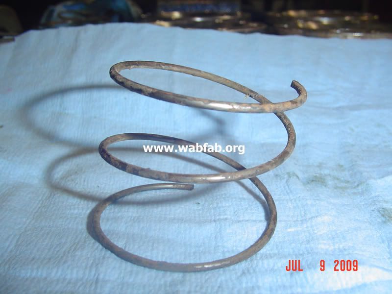
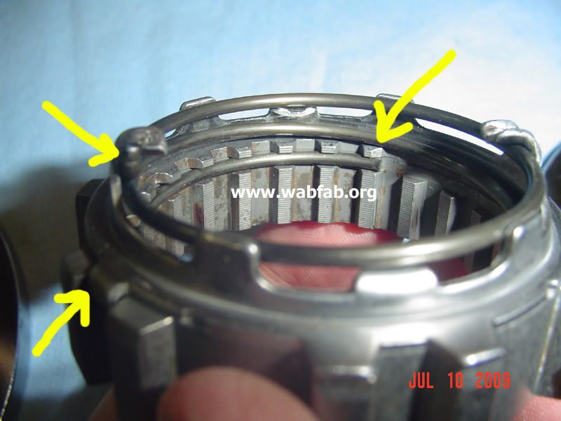
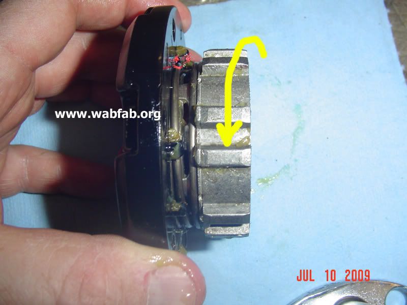
Note the arrows and how the spring sits on the guide.
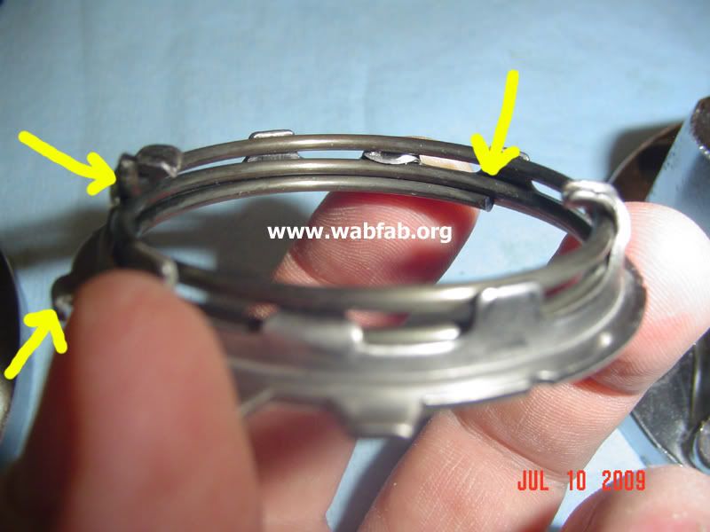
Arrows pointing out where spring should start.
Arrows pointing out where spring should start.
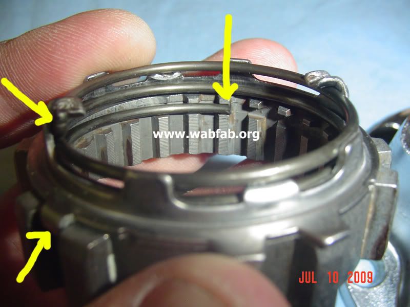
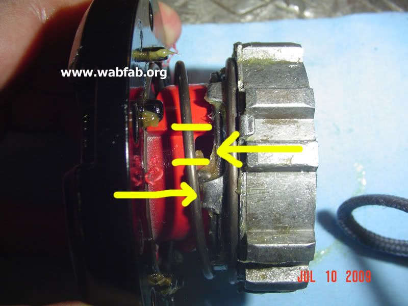
Arrows pointing out where spring should end up.
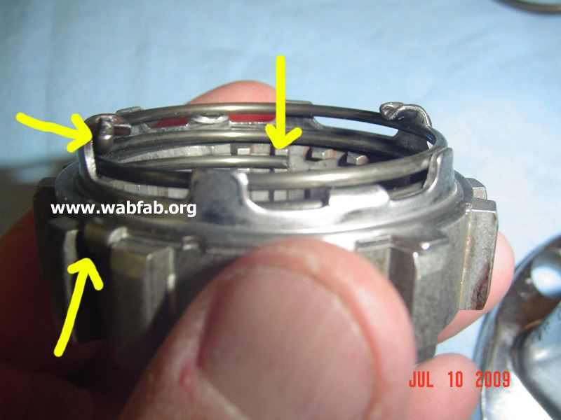
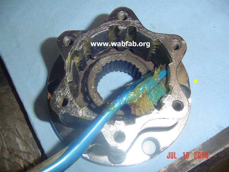
The little spring and ball go in the hole above the little silver triangle and the o-ring wraps around the dial.
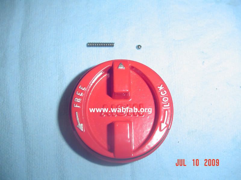
This is why you should replace your hub dial o-rings when you regrease them.
Insert the detent ball into the "FREE" notch on the back of the hub dial face and secure with clip.
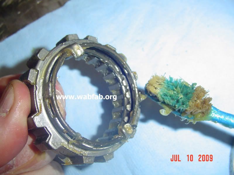
Use an old tootbrush and slightly grease the whole clutch mechanishm.
The flat side goes down on the clutch pawl so that the slanted side of the big spring is towards the back of the red dial.
Turn it on counterclockwise or towards you in this picture.
The little bump sticking up on the clutch goes in the notch on the backside of the dial, then twish counter clockwise. Put these two pieces together with the dial in the FREE position.
Note that the little notch goes into the big space below as it will not fit into the smaller notches.
Lightly grease the whole inside with your toothbrush.
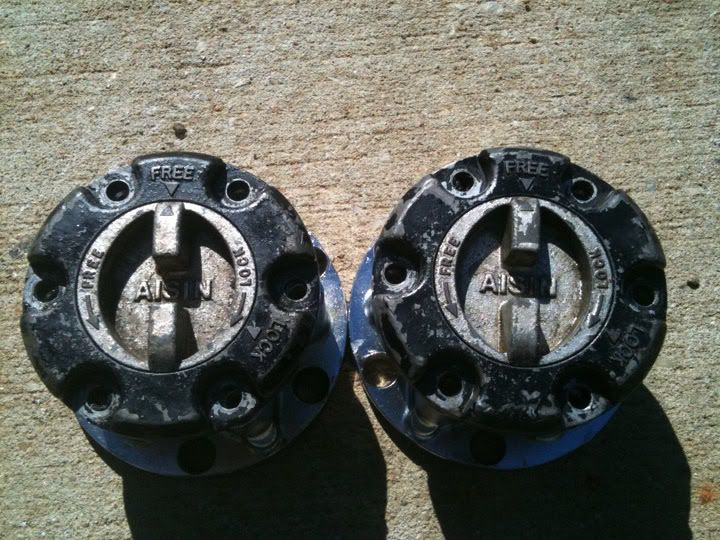
This is how I got them
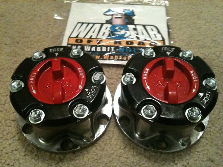
This is how they went back after getting the WabFab refurbishment treatment.
http://www.se4rj.com/forum/showthread.php?t=293
all of this info is from Waskillywabbit's AIsin hub rebuilt how to in the link above:
Toyota Aisin manual hubs are a nice upgrade over ADD and auto hubs found on various Toyota 4x4s, 79-95. During this time period you have solid front axles (SFA) on pickups and 4Runners, and independent front suspensions (IFS) on the same. I am talking strictly about these years and models. There are numerous other Aisin manual hubs and many of those parts are useful as well.
SFA on the left, IFS on the right in the pictures
The red dials are interchangeable on various types of Aisins, with one noticeable difference that disinguishes the SFA dial on the left, it has a raised and curved "handle" for easier gripping. Since the dials are interechangeable do not always assume what kind of hub you have without looking at several factors that distinguish the two, as mentioned below. I have purchased quite a few Aisins that folks thought were IFS and actually turned out to be SFA, thus I got them on the cheap and was pleasantly surprised.
The black face is the same on the SFA and IFS and are easily interchangeable as are the hub dial o-ring, and the little ball and spring located in the little hole on the dials. If you decide to clean your Aisins and disassemble them, be careful not to lose the little ball and spring. The number one thing missing on Aisins I purchase are these items, thus the reason I found a source for them so I could replace them.
The big springs are all the same, but you must install them correctly. Here is the difference.
This is flat side up.
This is flat side down.
You want to install the spring flat side down towards the clutch (see next pic).
The clutch spring mechanism is interchangeable but the clutches themselves are different, and different enough that you can't put the SFA one in the IFS, but it will work vice versa, due to the height difference. I don't swap them myself as it can cause issues of fitment in certain instances. SFA is on the left and taller than the IFS one on the right.
The biggest difference is the hub gear, SFA is 30 spline and the IFS is 26 spline, yep I counted them. While interchangeable in the hub assembly, they are not usable if swapped due to clearances and fitments. Examing the hub from the backside of the flange and seeing the hub gear splines and the difference in the recession on the face of the flange is the sure fire way to tell the difference as to what type of Toyota Aisin manual hub you have. SFA is on the left and shallower, IFS on the right and deeper.
Note the arrows and how the spring sits on the guide.
Arrows pointing out where spring should start.
Arrows pointing out where spring should start.
Arrows pointing out where spring should end up.
The little spring and ball go in the hole above the little silver triangle and the o-ring wraps around the dial.
This is why you should replace your hub dial o-rings when you regrease them.
Insert the detent ball into the "FREE" notch on the back of the hub dial face and secure with clip.
Use an old tootbrush and slightly grease the whole clutch mechanishm.
The flat side goes down on the clutch pawl so that the slanted side of the big spring is towards the back of the red dial.
Turn it on counterclockwise or towards you in this picture.
The little bump sticking up on the clutch goes in the notch on the backside of the dial, then twish counter clockwise. Put these two pieces together with the dial in the FREE position.
Note that the little notch goes into the big space below as it will not fit into the smaller notches.
Lightly grease the whole inside with your toothbrush.
This is how I got them
This is how they went back after getting the WabFab refurbishment treatment.
Last edited by dropzone; Jun 21, 2012 at 09:45 PM. Reason: added pics
Jun 21, 2012 | 08:53 PM
#110
79-80 Truck owners have been kind of getting the short end of the stick when trying to do the conversion with V-6 Calipers and FJ Vented Rotors. I found this info on Marlin:
paged 103 of this thread: http://board.marlincrawler.com/index...213#quickreply
paged 103 of this thread: http://board.marlincrawler.com/index...213#quickreply
for those 79 and 80 owners you don't need to swap to 81-85 hubs. just drill 4 holes.
79 pickup hub

LandCruiser rotor

Land cruiser rotor sitting on the 79 hub. notice the two small holes are lined up with two of the holes that the 79 rotor used to bolt to the 79 hub

79 pickup hub
LandCruiser rotor
Land cruiser rotor sitting on the 79 hub. notice the two small holes are lined up with two of the holes that the 79 rotor used to bolt to the 79 hub
then using a 5/16 drill bit line up the threaded holes and drill the new 4 holes in the rotor.

once they are drilled remove the rotor and use a 3/8 drill bit and open them up so the bolts slip through and then bolt it on with the original 6 bolts.


once they are drilled remove the rotor and use a 3/8 drill bit and open them up so the bolts slip through and then bolt it on with the original 6 bolts.
Jul 24, 2012 | 07:53 AM
#111
door panel repair/grade restoration
Grego92 did an awesome write up on door panel repair. I think it can apply to any application
Original thread here
Original thread here
Put this on my build thread and putting a modified copy on the forum in case someone searches in the future on wanting to repair or upgrade their door panels.
I�m more of a highway driver with my truck so I wanted SR5 cloth door panels with manual windows for some time now. Finally pieced a set together from the junk yard from two separate pickups. One cost me $17 and the other $9. So long as the fabric is up to your liking and standard you can still salvage them to work and look nice.
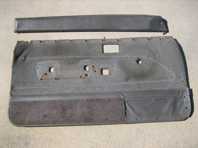
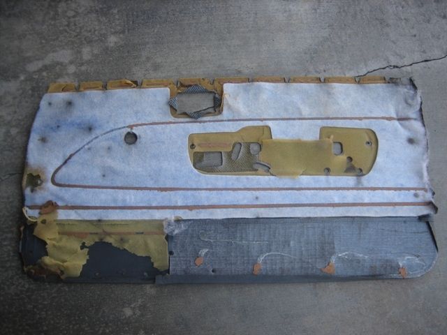
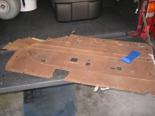
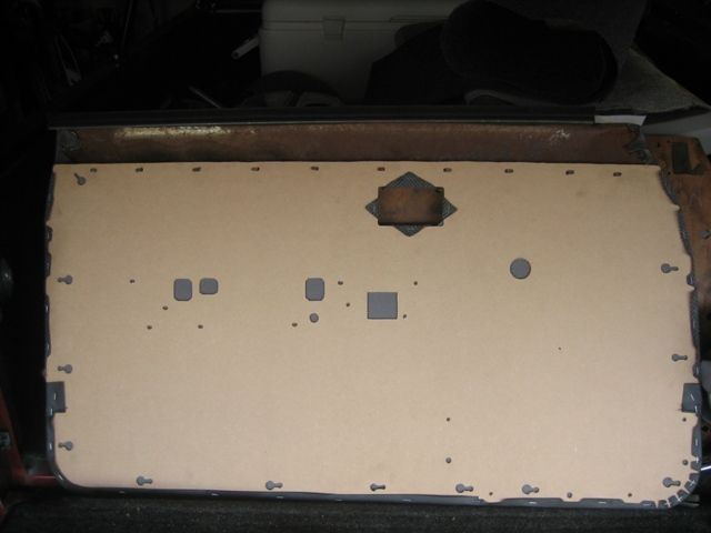
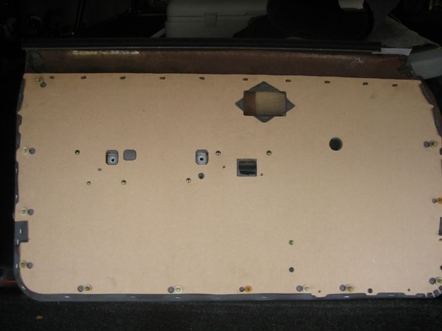
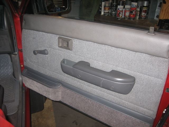
To clean the dirt, stains, and oil off, I scrubbed them down with laundry detergent and then fully air dried. In hindsight, you might want to remove the material from the board before cleaning to prevent further damage from the water. The panels I had were already bent, warped, and torn so I didn�t bother removing the material first before cleaning. Passenger side:

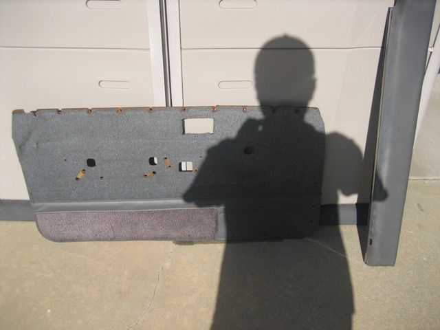
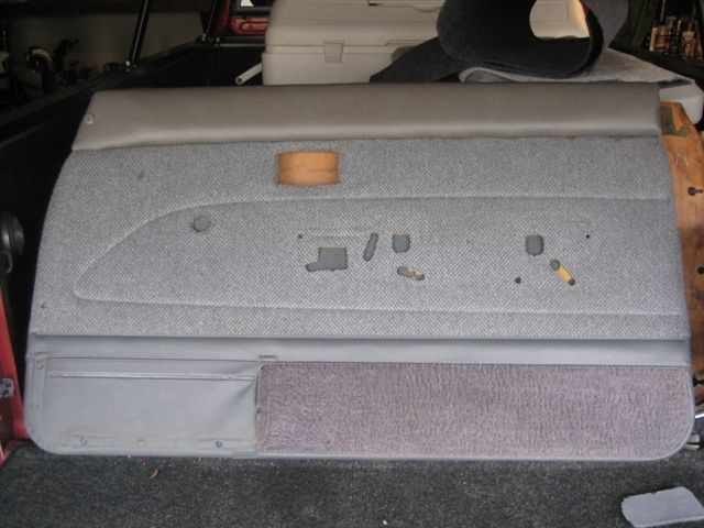
Drivers side. You'll notice the armrest pad is separated, it was already ripped from the board when I found it.
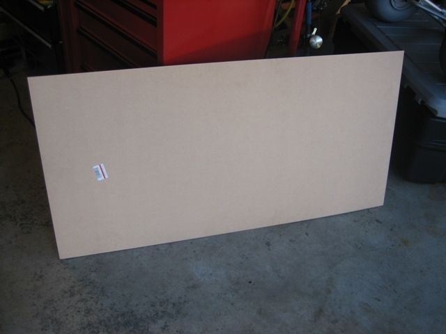
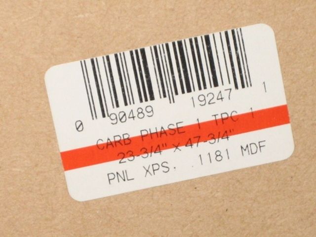
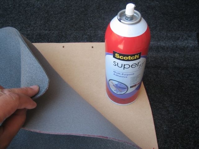
Knowing I needed to replace the particle board I went to Home Depot and purchased two approximately 2' x 4' sheets of 1/8" MDF particle board. This was nice stuff and was smooth on both sides. Cost about $4 each.
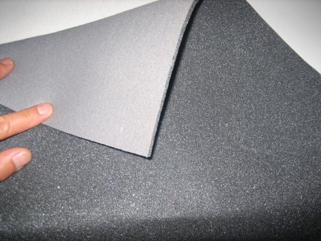
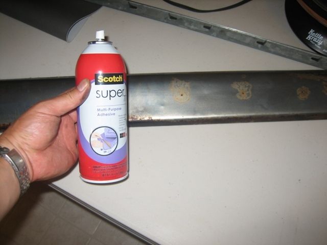
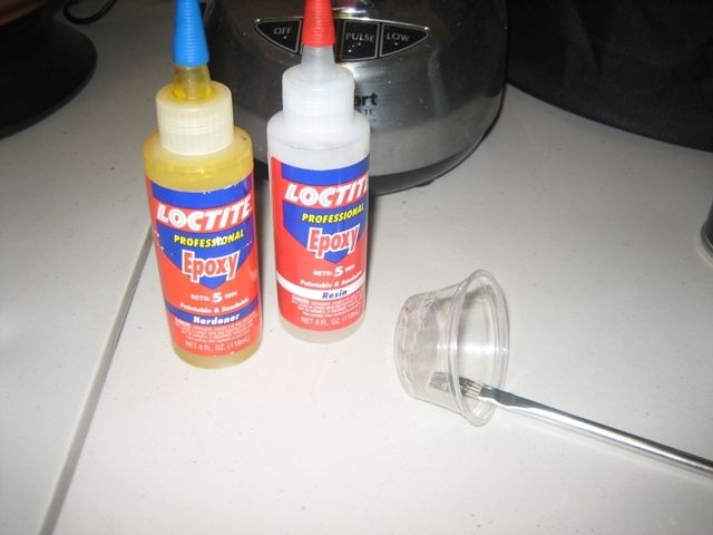
Went to a craft store called Michael's and bought headliner foam padding and grey vinyl material. The foam had felt like material covering one side of it and was about 1/8" thick. You�ll need enough foam to cover the door panel(s) and arm rests. You�ll need enough vinyl to cover the two arm rests. Cost about $20 using a 50% off coupon that the register lady gave me. Also, picked up a can of 3M spray adhesive.
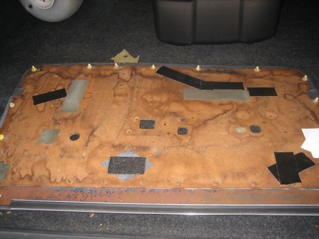
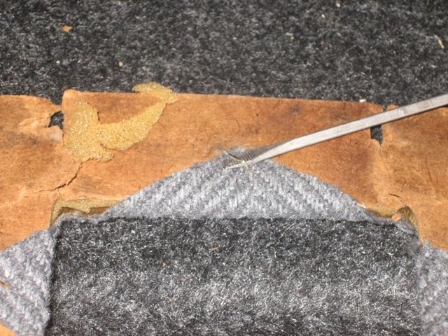
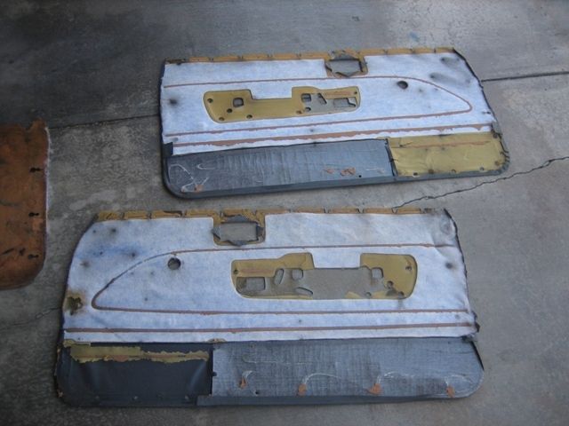
Step 1 - Remove existing door panel material
If re-using the material carefully remove all the staples (front and back sides) and peel/separate all the vinyl and cloth material from the boards. Some of the adhesive is pretty sticky.
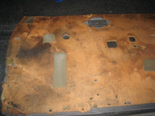
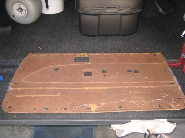
Badly damaged panel.
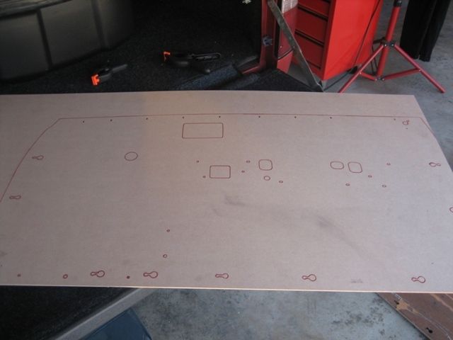
You will need at least one good board in order to make a template, hopefully the other side is in better condition or you�ll probably have to tape and mend what you have to work with.
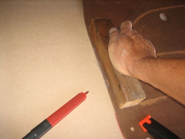
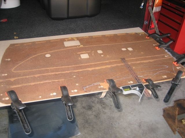
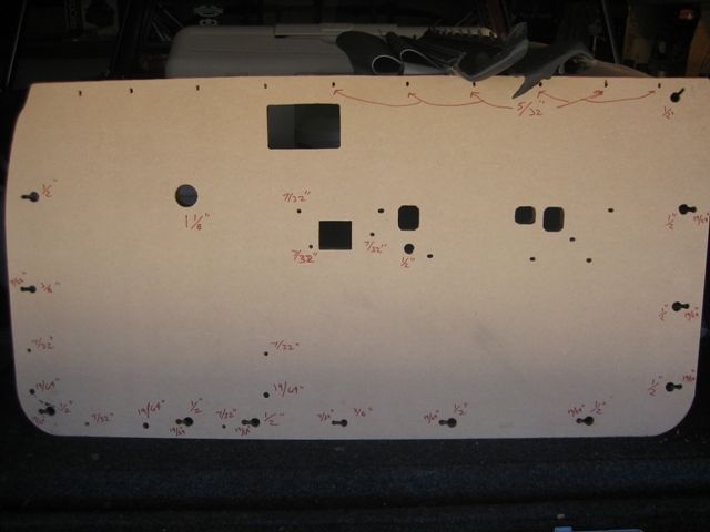
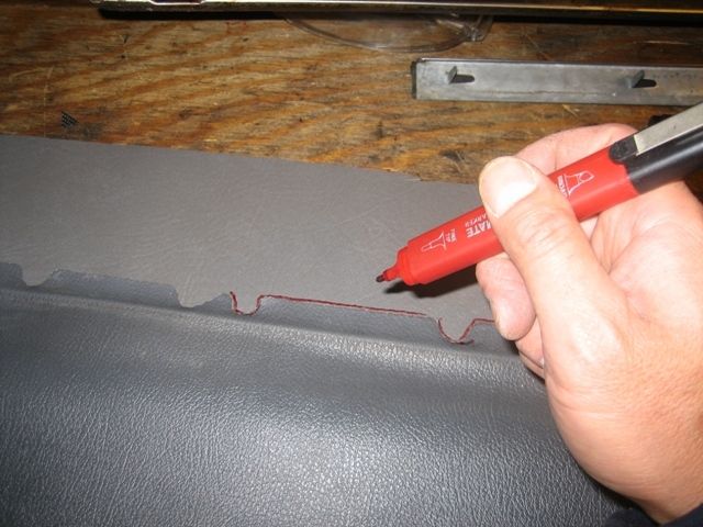
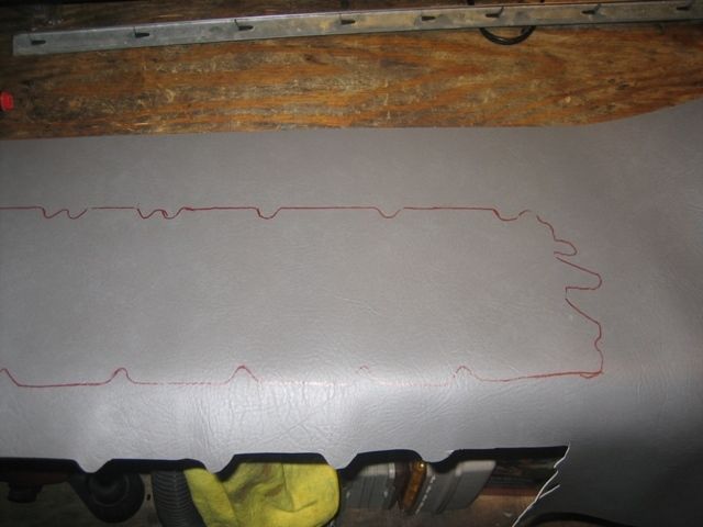
Step 2 - Make the template
Using clamps and a marker trace the panel. You can use a block of wood to push down on the warped panel to get the cleanest and most accurate trace.
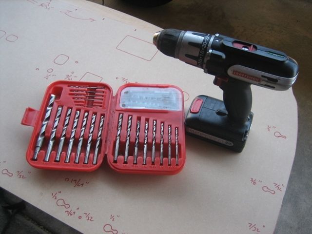
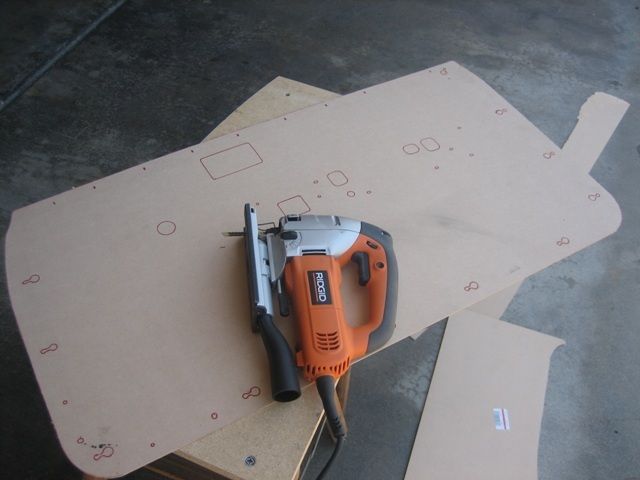
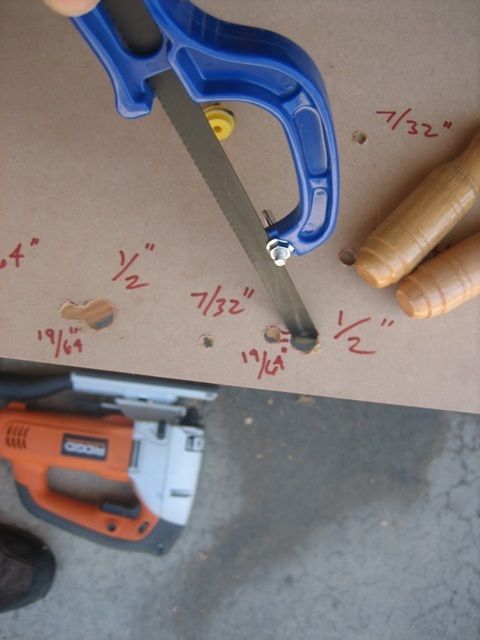
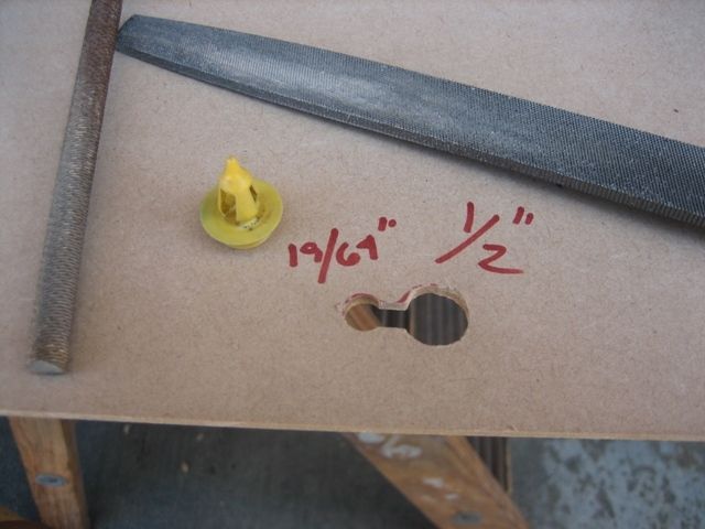
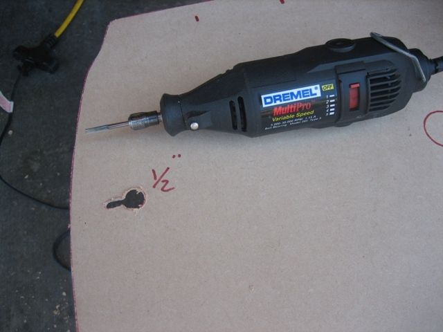
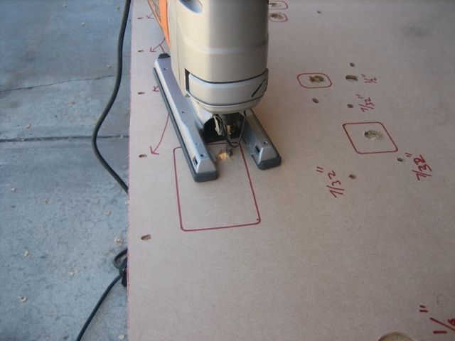
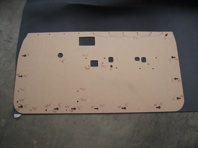
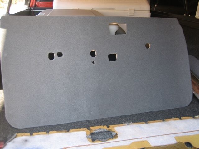
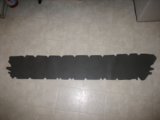
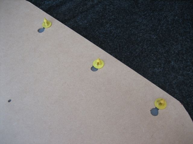
Step 3 - Making the cuts
Using whatever tools you have (Jig Saw, Drill and different bits, Small Hand Saw, Dremel Tool, and Files) cut out the patterns to resemble the original door card panel. You'll notice I labeled the different size bits I used to make most of the holes to make the cutting of the 2nd panel a bit quicker. Use a cylinder and straight file to make final adjustments so that the plastic pieces that hold the card to the door fit correctly.

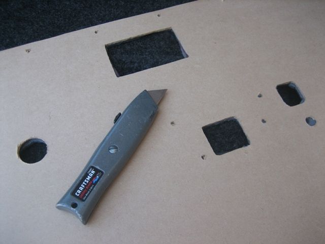
Step 4 - Foam Padding
This isn�t necessary, however I wanted a plusher feeling and additional sound dampening. Lay down the foam headliner material and trace/cut to the outline of the panel. Use the spray adhesive to glue it to the new door card (felt side down), and then use a box cutter to cut out the necessary openings.
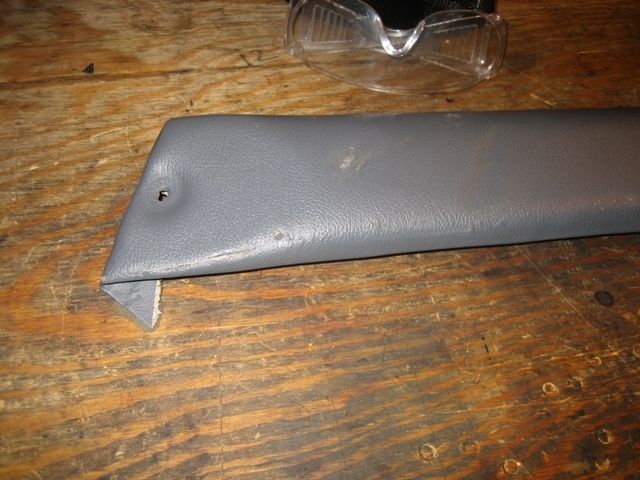
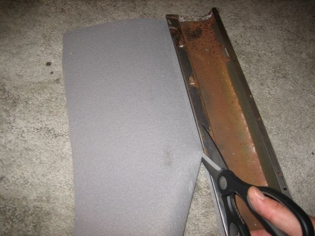
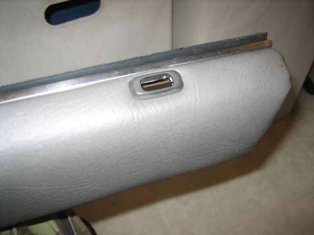
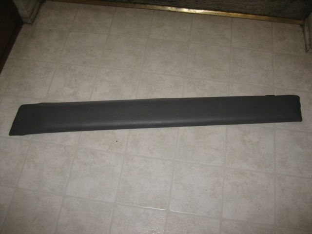
Step 5 - PITA Arm Rests
I like to ride with my window down and arm resting on the door. If you're familiar with our non-SR5 door panels you've noticed the arm pad is not very thick and has no padding, which means not very comfortable. I decided to address that with extra foam padding since I was putting new vinyl on. This part takes some patience.
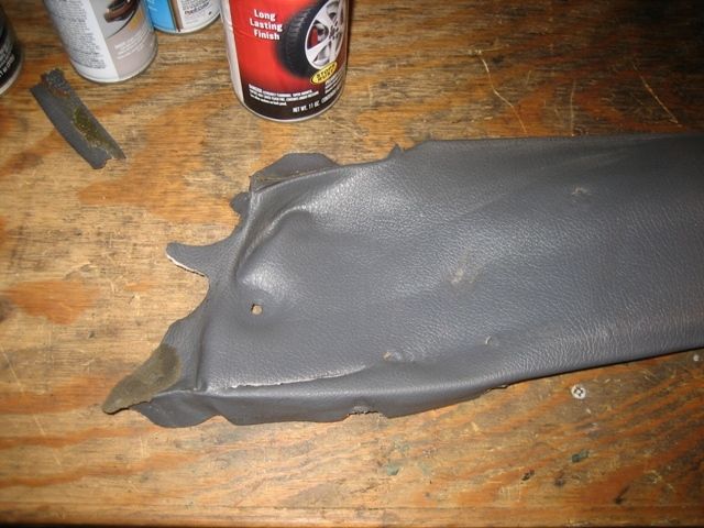
Bad vinyl
Straighten out metal clips to pull window piece off
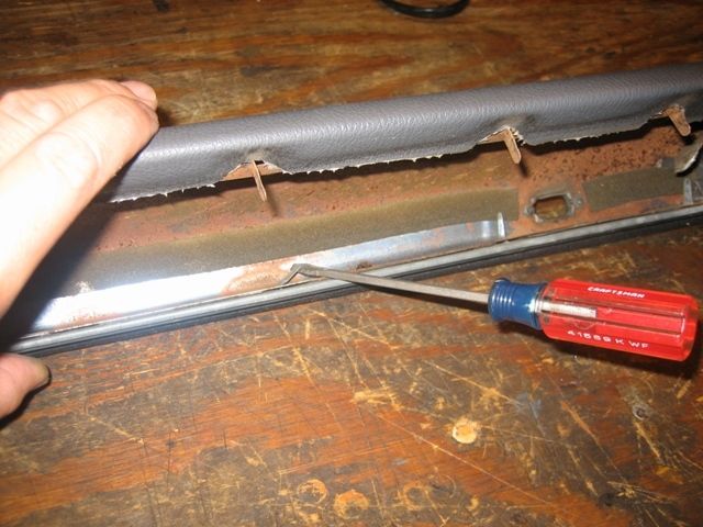
Peel off the old vinyl
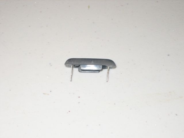
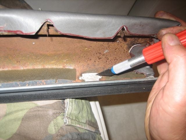
Remove the door lock plastic trim piece. The plastic pieces are melted at the ends to keep them in place so you'll either have to melt them off or just do what I did and break them off and find a substitute replacement. The 2nd Gen Camry (89-91) pieces are a good substitute. The camry's have metal tabs so you can easily remove and re-use them. I had a few extra from the junk yard for my camry so I used them on these arm pads.
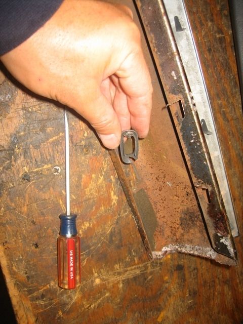
Camry replacement piece
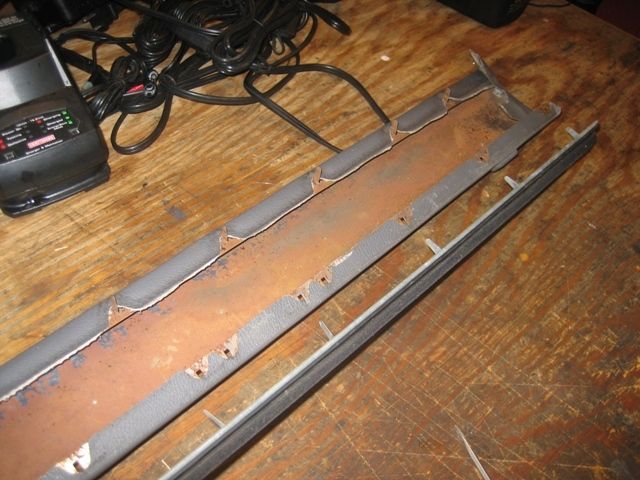
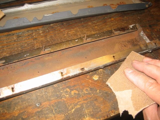
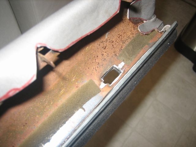
Sand off any rust and sticky residue so the new glue will adhere better
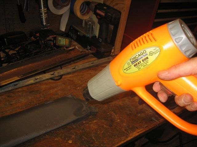
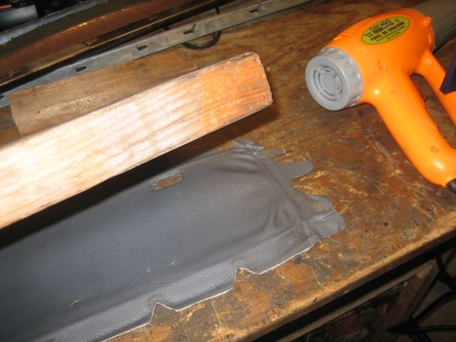
Flatten out the old vinyl so you can use it as a template. A heat gun and board makes quick work of flattening it out so you can trace it easier.
Trace and cut your vinyl skin template
Trace, cut and glue the head liner foam for extra padding.
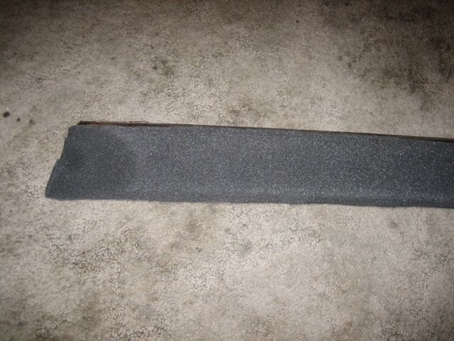
I opted to use a thicker and denser foam padding I had laying around on the top portion of the arm rest.
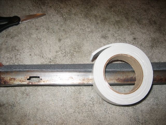
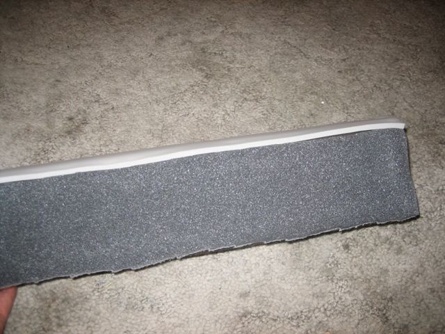
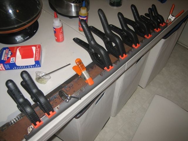
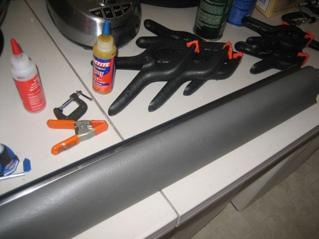
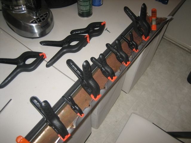
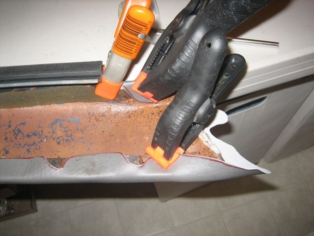
Now is the PITA part, use a good adhesive to get the vinyl stretched and stuck over the arm pad. You'll need a BUNCH of clamps! The ends are the hardest part.
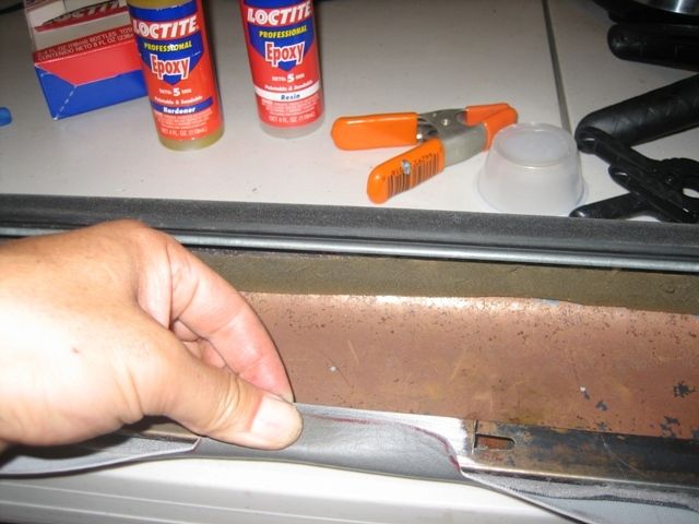
Then after it dries you can cut out the door lock hole and put the plastic camry piece in. The metal tabs just fold over to hold it in place.
Step 6 � Putting it together
Place the cleaned material onto the bew door card and either staple or glue or both in place. I used 1/4" staples.
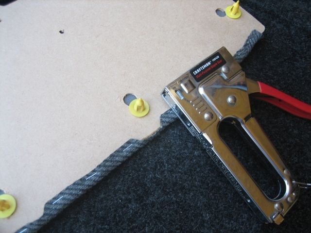
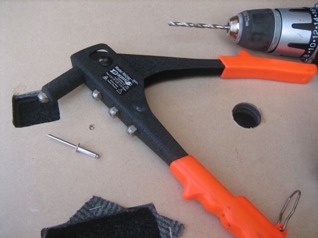
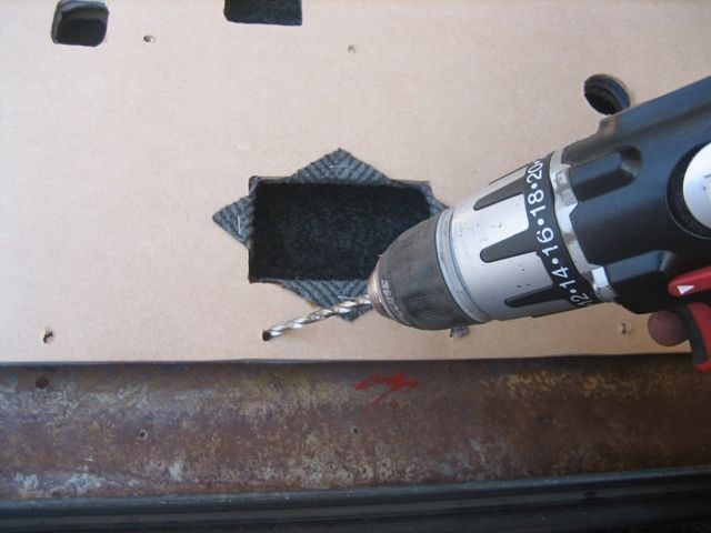
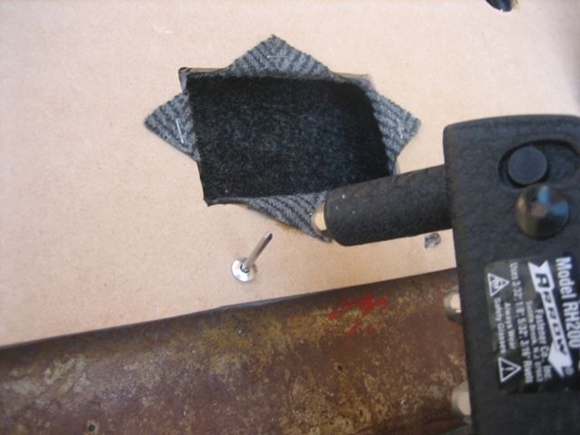
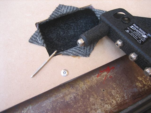
Put the arm rest on by inserting the tabs through the top holes on the board and bend them down to hold in place. If some of the tabs have broken off, you can substitute rivets to hold it in place. I drilled the appropriate hole size for the rivet and used a cheap hand powered pop rivet gun.
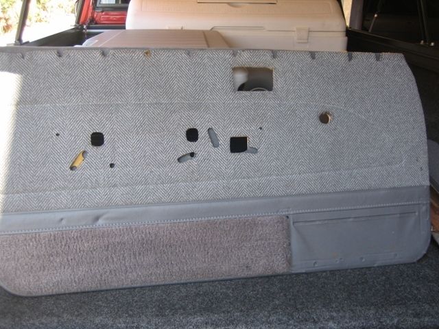
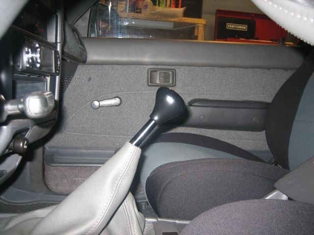
Lastly, grab grab your door handles and map pocket and screw them in. I had previously found the SR5 door handles and carpeted map pockets from a 2nd Gen 4runner.
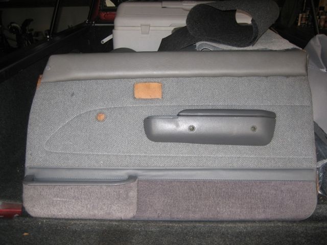
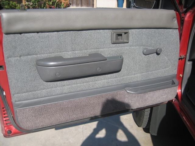
Now mount it up and see how it looks! You'll notice when placing the plastic retaining pieces in why you don't need to cut through the foam for those holes. Enjoy having some nicer looking panels, a little more comfortable arm rests, and additional sound proofing.
Passenger side.
Driver side.
I�m more of a highway driver with my truck so I wanted SR5 cloth door panels with manual windows for some time now. Finally pieced a set together from the junk yard from two separate pickups. One cost me $17 and the other $9. So long as the fabric is up to your liking and standard you can still salvage them to work and look nice.
To clean the dirt, stains, and oil off, I scrubbed them down with laundry detergent and then fully air dried. In hindsight, you might want to remove the material from the board before cleaning to prevent further damage from the water. The panels I had were already bent, warped, and torn so I didn�t bother removing the material first before cleaning. Passenger side:
Drivers side. You'll notice the armrest pad is separated, it was already ripped from the board when I found it.
Knowing I needed to replace the particle board I went to Home Depot and purchased two approximately 2' x 4' sheets of 1/8" MDF particle board. This was nice stuff and was smooth on both sides. Cost about $4 each.
Went to a craft store called Michael's and bought headliner foam padding and grey vinyl material. The foam had felt like material covering one side of it and was about 1/8" thick. You�ll need enough foam to cover the door panel(s) and arm rests. You�ll need enough vinyl to cover the two arm rests. Cost about $20 using a 50% off coupon that the register lady gave me. Also, picked up a can of 3M spray adhesive.
Step 1 - Remove existing door panel material
If re-using the material carefully remove all the staples (front and back sides) and peel/separate all the vinyl and cloth material from the boards. Some of the adhesive is pretty sticky.
Badly damaged panel.
You will need at least one good board in order to make a template, hopefully the other side is in better condition or you�ll probably have to tape and mend what you have to work with.
Step 2 - Make the template
Using clamps and a marker trace the panel. You can use a block of wood to push down on the warped panel to get the cleanest and most accurate trace.
Step 3 - Making the cuts
Using whatever tools you have (Jig Saw, Drill and different bits, Small Hand Saw, Dremel Tool, and Files) cut out the patterns to resemble the original door card panel. You'll notice I labeled the different size bits I used to make most of the holes to make the cutting of the 2nd panel a bit quicker. Use a cylinder and straight file to make final adjustments so that the plastic pieces that hold the card to the door fit correctly.
Step 4 - Foam Padding
This isn�t necessary, however I wanted a plusher feeling and additional sound dampening. Lay down the foam headliner material and trace/cut to the outline of the panel. Use the spray adhesive to glue it to the new door card (felt side down), and then use a box cutter to cut out the necessary openings.
Step 5 - PITA Arm Rests
I like to ride with my window down and arm resting on the door. If you're familiar with our non-SR5 door panels you've noticed the arm pad is not very thick and has no padding, which means not very comfortable. I decided to address that with extra foam padding since I was putting new vinyl on. This part takes some patience.
Bad vinyl
Straighten out metal clips to pull window piece off
Peel off the old vinyl
Remove the door lock plastic trim piece. The plastic pieces are melted at the ends to keep them in place so you'll either have to melt them off or just do what I did and break them off and find a substitute replacement. The 2nd Gen Camry (89-91) pieces are a good substitute. The camry's have metal tabs so you can easily remove and re-use them. I had a few extra from the junk yard for my camry so I used them on these arm pads.
Camry replacement piece
Sand off any rust and sticky residue so the new glue will adhere better
Flatten out the old vinyl so you can use it as a template. A heat gun and board makes quick work of flattening it out so you can trace it easier.
Trace and cut your vinyl skin template
Trace, cut and glue the head liner foam for extra padding.
I opted to use a thicker and denser foam padding I had laying around on the top portion of the arm rest.
Now is the PITA part, use a good adhesive to get the vinyl stretched and stuck over the arm pad. You'll need a BUNCH of clamps! The ends are the hardest part.
Then after it dries you can cut out the door lock hole and put the plastic camry piece in. The metal tabs just fold over to hold it in place.
Step 6 � Putting it together
Place the cleaned material onto the bew door card and either staple or glue or both in place. I used 1/4" staples.
Put the arm rest on by inserting the tabs through the top holes on the board and bend them down to hold in place. If some of the tabs have broken off, you can substitute rivets to hold it in place. I drilled the appropriate hole size for the rivet and used a cheap hand powered pop rivet gun.
Lastly, grab grab your door handles and map pocket and screw them in. I had previously found the SR5 door handles and carpeted map pockets from a 2nd Gen 4runner.
Now mount it up and see how it looks! You'll notice when placing the plastic retaining pieces in why you don't need to cut through the foam for those holes. Enjoy having some nicer looking panels, a little more comfortable arm rests, and additional sound proofing.
Passenger side.
Driver side.
 Dec 11, 2012 | 07:36 PM
#114
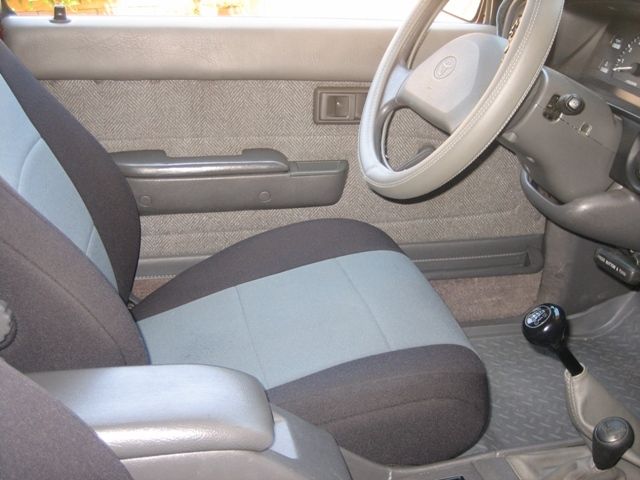
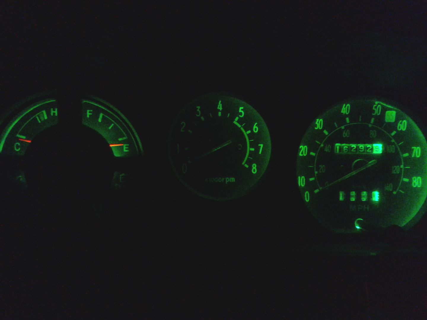
LED Dash light conversion:
after 30 years the bulbs in 1st gen trucks are pretty anemic/ for just the guages you will need 6, 13 total if you convert all the bulbs
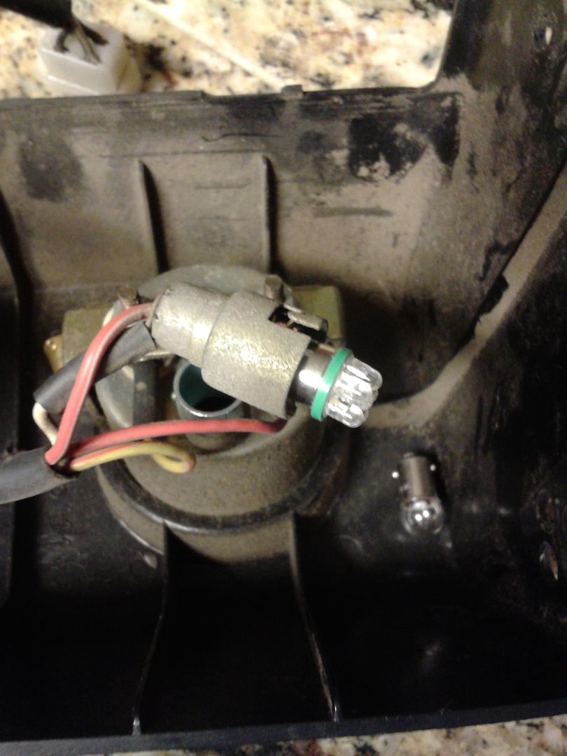
remove the cluster and you will find the bulb holders, just untwist them and swap out the 194's for the LED's

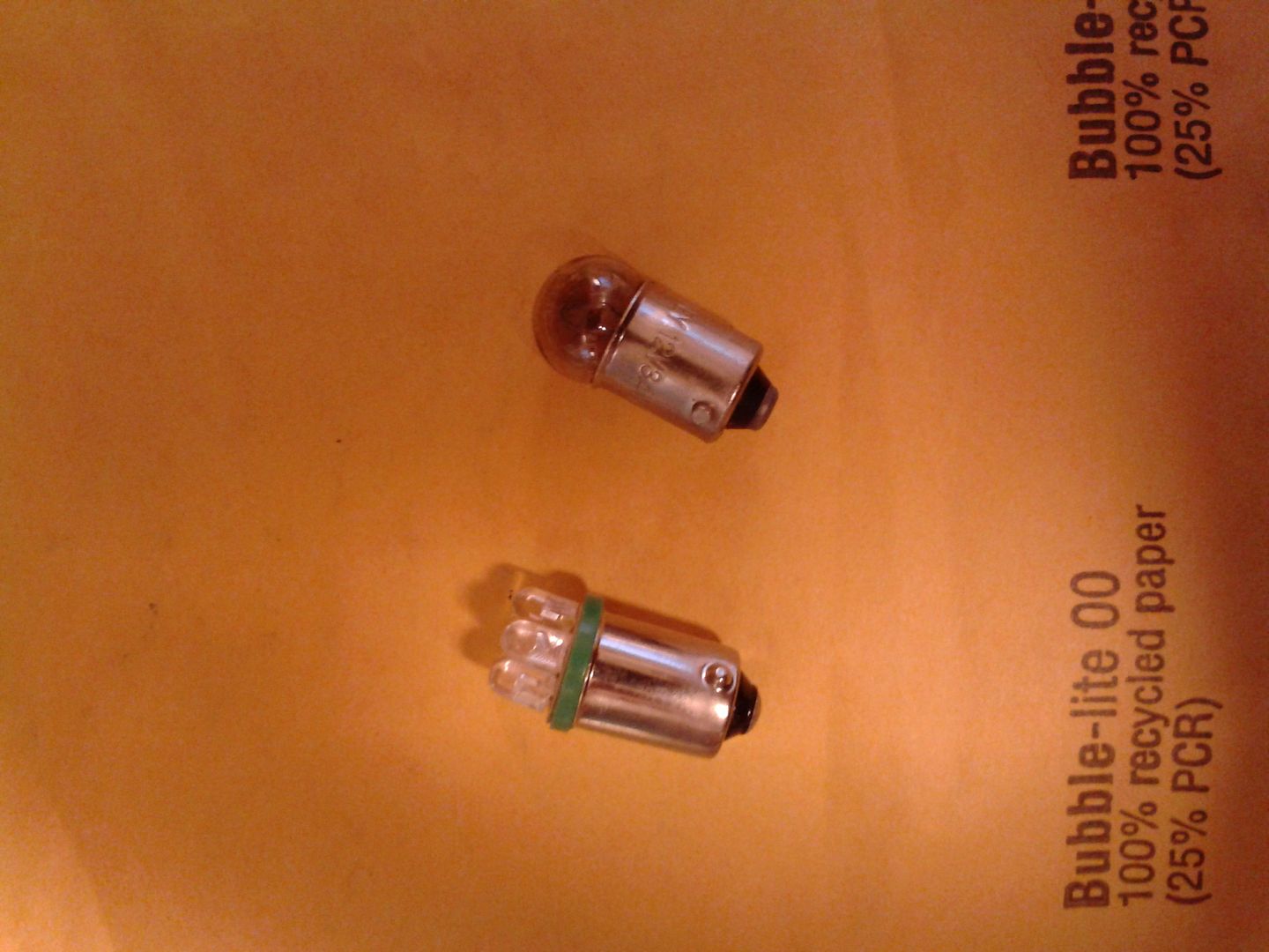
stock bulb on left, LED on right..
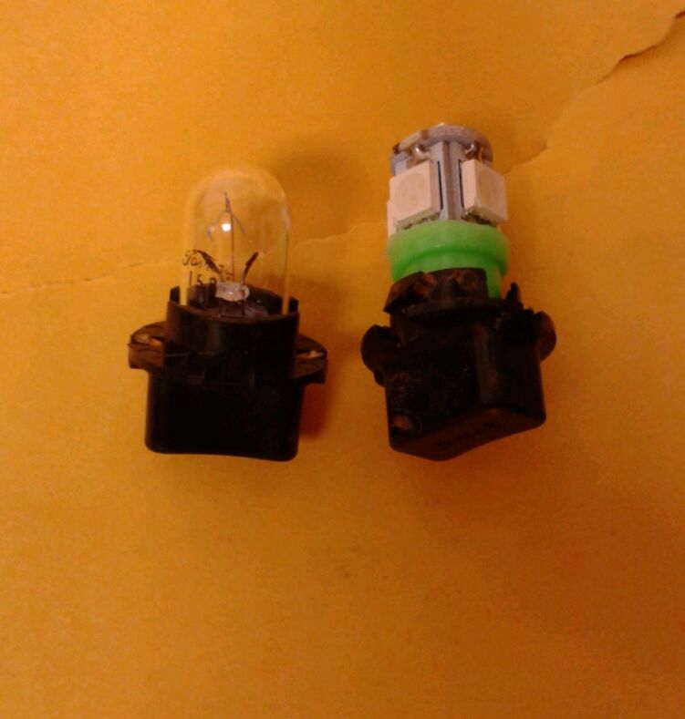
stock bulbs are 194's, if you search superbrightleds.com for 194 LED or T10 you will find a wide assortment available and a wide price range..I got mine off ebay, 10 for $9.99..again there is a wide variety of options and prices
stock bulbs
green bulbs with 5 SMD LED's
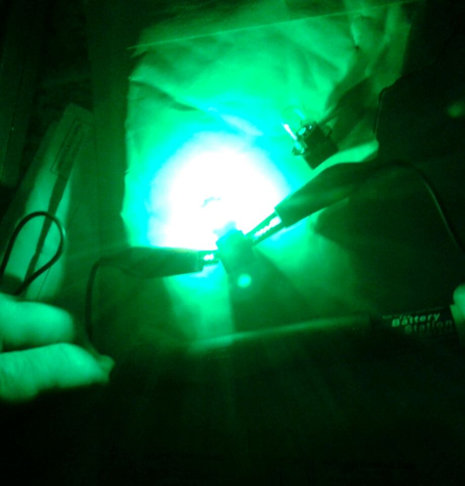
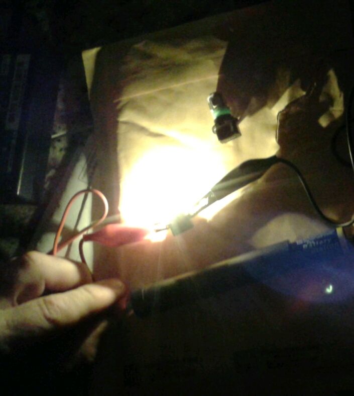
installed:
edit:
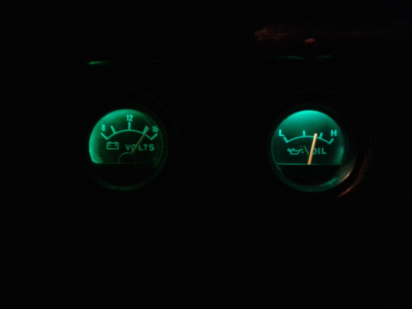
Threw a couple of LED's into the Voltmeter and Oil pressure gauge cluster.
the bulb is a 1445, I just searched 1445 LED bulb on ebay. got a couple of them for $5 delivered.
old anemic output again...I don't think the voltmeter lamp was working..

after 30 years the bulbs in 1st gen trucks are pretty anemic/ for just the guages you will need 6, 13 total if you convert all the bulbs
remove the cluster and you will find the bulb holders, just untwist them and swap out the 194's for the LED's
stock bulb on left, LED on right..
stock bulbs are 194's, if you search superbrightleds.com for 194 LED or T10 you will find a wide assortment available and a wide price range..I got mine off ebay, 10 for $9.99..again there is a wide variety of options and prices
stock bulbs
green bulbs with 5 SMD LED's
installed:
edit:
Threw a couple of LED's into the Voltmeter and Oil pressure gauge cluster.
the bulb is a 1445, I just searched 1445 LED bulb on ebay. got a couple of them for $5 delivered.
old anemic output again...I don't think the voltmeter lamp was working..
Last edited by dropzone; Dec 27, 2012 at 05:47 PM.
Jul 7, 2014 | 02:39 AM
#115

Registered User
Joined: Jul 2014
Posts: 3
Likes: 0
wiring light upgrade...
here is the wiring I'm using on my lights. works well so far... not trail tested yet.
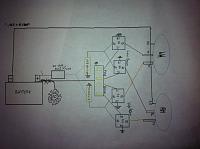
Actually, believe I'm using two five pin relays instead of the four 4-pins as shown in the pic. Pic is a rough wiring as I can't find the one showing the one I'm using. Will update if I locate it. Anyway the idea behind the wiring allows 3 light settings. The use of high beam, the use of low beam and the use of high and low at the same time. Uses stock lights

Actually, believe I'm using two five pin relays instead of the four 4-pins as shown in the pic. Pic is a rough wiring as I can't find the one showing the one I'm using. Will update if I locate it. Anyway the idea behind the wiring allows 3 light settings. The use of high beam, the use of low beam and the use of high and low at the same time. Uses stock lights
Feb 20, 2015 | 12:44 AM
#116
Dash Pad Redo
it has been awhile since this thread had a decent update.
A couple of years ago or so I picked up a dash pad at a local pick n pull while on a parts run with TrekkerPaul. The dash pad was in slightly better shape than my cracked to crap dashpad but it was still in need of work.
Using Corax's Fiberglass Dash Thread as a guide i started this summer of 2014.
Using a donor dash frame made the work outside of the truck easier:

Cut out some fiberglass mesh that was left over from my bed bob project:

Layer the resin down:

I tried to use some foil in an effort to protect the dash frame to keep fiberglass from sticking but that was a lost cause.
Here it is with 3 layers of fiberglass, I filled the center dash pocket with resin. I sanded with with 80, 100, than 150 grit.

I wanted a texture to the dash pad so I used some Herculiner or Duraliner:


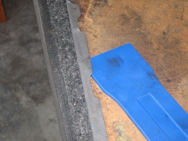
Harbor Freight has some cool little plastic prybars that work great for using on interior clips:

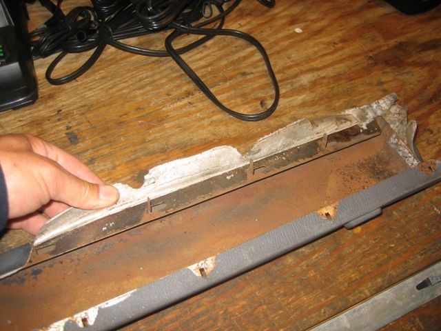
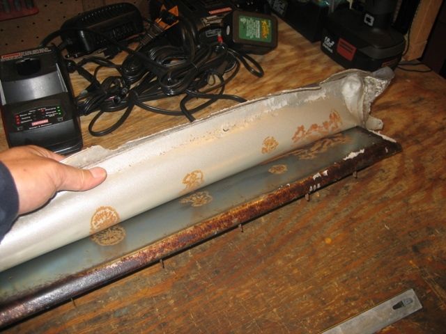
used them to pull out the old dash pad:


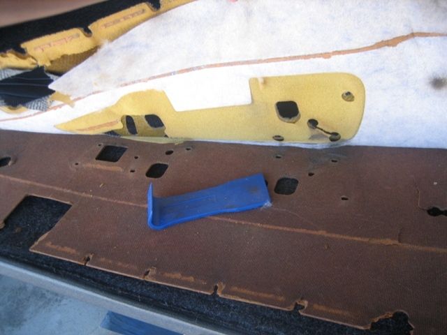
little bit of random 1st Gen trivia, not sure what year i pulled this dash pad out of but it did not have as many retaining clips as the stock 81 dash pad:
new dash on left, old dash on right

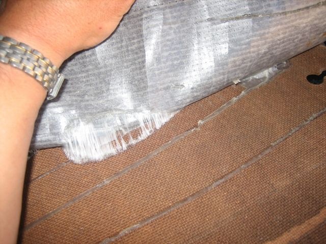
-one thing to see in the above picture is the material that overlaps the main part of the dash, they are used to help old the dash in place by the front edge of the glove box and vent areas. I ended up with a lot of resin over run and had to try to peel it off with out damaging the material..kind of a PITA.
-if you use your current dash pad, try to save all the retaining clips, some of mine broke when I pulled the dash pad, also put masking tape or something over the metal slots where the retainer slide into to keep fiberglass from seeping into it.
Not perfect by any means but better than looking at the ragged out POS i had before.

not sure what the overall cost was, i used left over materials from when I bobbed the bed and extended my rear hatch.
I probably had 7-10 hours on it. Hard to say though since i started the project last summer.
A couple of years ago or so I picked up a dash pad at a local pick n pull while on a parts run with TrekkerPaul. The dash pad was in slightly better shape than my cracked to crap dashpad but it was still in need of work.
Using Corax's Fiberglass Dash Thread as a guide i started this summer of 2014.
Using a donor dash frame made the work outside of the truck easier:

Cut out some fiberglass mesh that was left over from my bed bob project:

Layer the resin down:

I tried to use some foil in an effort to protect the dash frame to keep fiberglass from sticking but that was a lost cause.
Here it is with 3 layers of fiberglass, I filled the center dash pocket with resin. I sanded with with 80, 100, than 150 grit.

I wanted a texture to the dash pad so I used some Herculiner or Duraliner:


Harbor Freight has some cool little plastic prybars that work great for using on interior clips:

used them to pull out the old dash pad:


little bit of random 1st Gen trivia, not sure what year i pulled this dash pad out of but it did not have as many retaining clips as the stock 81 dash pad:
new dash on left, old dash on right

-one thing to see in the above picture is the material that overlaps the main part of the dash, they are used to help old the dash in place by the front edge of the glove box and vent areas. I ended up with a lot of resin over run and had to try to peel it off with out damaging the material..kind of a PITA.
-if you use your current dash pad, try to save all the retaining clips, some of mine broke when I pulled the dash pad, also put masking tape or something over the metal slots where the retainer slide into to keep fiberglass from seeping into it.
Not perfect by any means but better than looking at the ragged out POS i had before.

not sure what the overall cost was, i used left over materials from when I bobbed the bed and extended my rear hatch.
I probably had 7-10 hours on it. Hard to say though since i started the project last summer.


