
I've got the blues
 May 22, 2003 | 09:45 PM
#41
Registered User
Joined: May 2002
Posts: 402
Likes: 0
From: LA, CA
Ok, window switch... Typing as a I go....
-Pop out switch panel. You don't need to take off the door panel. Pops out, unplug two plugs.
-Two screws on the back, remove.
-flip back over, 4 black screws on top, remove.
-Now, this part, I'm not sure of. You gotta slide the top off somehow. When I did it, I heard a CRAPLOAD of stuff falling out/around inside. Opened it up and there were a buncha little pieces everywhere. I don't know how everything fits together... There's two silver springs that don't appear to go anywhere. Everything else seems to go somewhere with no problem. Well, I'll cross that bridge when I come to it.
Oh crap. Just lost a spring. Oh, well, no more window lock... :pat:
FOUND IT!!! Ugh.. looking through the trash for a tiny spring is not fun. NOTE: don't play with the window lock switch because there's a spring on the back that pops off if you push down on it.
-Ok, back to the LED.
-the LED is on the underside of the black thing on a green PCB board, held in by melted plastic.
-OH, the silver springs are for the LED board contacts. They go on two posts on the white piece. *refer to Bill's picture to see what pieces I'm talking about*
-The board is held in in a way similar to Bob's method of fastening the velcro for his V1. "Later, using an old plastic modeler's trick, I took a hot screwdriver and melted the bottom of it flat so as to create a more permanent mount:" To "unflatten" it, I used needle nose pliers and squeezed it until it was thin enough to slide the board off. It looks like Toyota also used 470 ohm 5% tolerance resistors.
-There is pin which the two front window switches pivot on. Remove the C-clip holding it in, remove it, and pull the driver's switch straight up.
-dremel out the LED hole to fit the new LED.
-Unsolder the old LED out, and solder the new one back in. NOTE: careful when unsoldering the old LED and don't be too rough. The solder pads separate easily from the PCB board. I just spent the last half hour repairing it :pat:
-I flattened the top of the LED w/ the dremel (or sandpaper) so that it would have better light dispersion and it looks a little better than leaving it round.
-put the board back, and use the sodlering iron to remelt the plastic
*-from here on, it's just reassembly!
-tip: when putting the black switch cover back on the white piece, the window lock switch's contact block is going to prevent it from closing. Use needle nose pliers to squeeze the contact block so that it slides in.
My driver's side window switch doesn't sound as nice anymore I think I need to get some grease and regrease it one of these days.
Well, that's the driver's side switch! I hope you guys find this useful! Good luck!
Coming in a couple days: Defrost and Hazard switches, cig lighter, ashtray, and glovebox lights! I still haven't gotten my lighting gels, and I can't find any place that has inkjet compatible transparencies so I don't know what to do about those Does anyone have a inkjet tranparency that I can buy?
-Pop out switch panel. You don't need to take off the door panel. Pops out, unplug two plugs.
-Two screws on the back, remove.
-flip back over, 4 black screws on top, remove.
-Now, this part, I'm not sure of. You gotta slide the top off somehow. When I did it, I heard a CRAPLOAD of stuff falling out/around inside. Opened it up and there were a buncha little pieces everywhere. I don't know how everything fits together...
There's two silver springs that don't appear to go anywhere. Everything else seems to go somewhere with no problem. Well, I'll cross that bridge when I come to it. Oh crap. Just lost a spring. Oh, well, no more window lock... :pat:
FOUND IT!!! Ugh.. looking through the trash for a tiny spring is not fun. NOTE: don't play with the window lock switch because there's a spring on the back that pops off if you push down on it.
-Ok, back to the LED.
-the LED is on the underside of the black thing on a green PCB board, held in by melted plastic.
-OH, the silver springs are for the LED board contacts. They go on two posts on the white piece. *refer to Bill's picture to see what pieces I'm talking about*
-The board is held in in a way similar to Bob's method of fastening the velcro for his V1. "Later, using an old plastic modeler's trick, I took a hot screwdriver and melted the bottom of it flat so as to create a more permanent mount:" To "unflatten" it, I used needle nose pliers and squeezed it until it was thin enough to slide the board off. It looks like Toyota also used 470 ohm 5% tolerance resistors.
-There is pin which the two front window switches pivot on. Remove the C-clip holding it in, remove it, and pull the driver's switch straight up.
-dremel out the LED hole to fit the new LED.
-Unsolder the old LED out, and solder the new one back in. NOTE: careful when unsoldering the old LED and don't be too rough. The solder pads separate easily from the PCB board. I just spent the last half hour repairing it :pat:
-I flattened the top of the LED w/ the dremel (or sandpaper) so that it would have better light dispersion and it looks a little better than leaving it round.
-put the board back, and use the sodlering iron to remelt the plastic
*-from here on, it's just reassembly!
-tip: when putting the black switch cover back on the white piece, the window lock switch's contact block is going to prevent it from closing. Use needle nose pliers to squeeze the contact block so that it slides in.
My driver's side window switch doesn't sound as nice anymore
I think I need to get some grease and regrease it one of these days.Well, that's the driver's side switch! I hope you guys find this useful! Good luck!
Coming in a couple days: Defrost and Hazard switches, cig lighter, ashtray, and glovebox lights! I still haven't gotten my lighting gels, and I can't find any place that has inkjet compatible transparencies so I don't know what to do about those
Does anyone have a inkjet tranparency that I can buy?
Last edited by DuB; May 22, 2003 at 09:46 PM.

 May 23, 2003 | 07:51 PM
#46
Registered User
Joined: May 2002
Posts: 402
Likes: 0
From: LA, CA
AUGH, I had a whole writeup for the defrost and hazard switches but a click on a link in AIM and POOF, it's all gone 

Well, it went something like this:
-first off, you should buy some grease to replace all the grease you wipe off from handling.
-Use the crutchfield instructions to figure out how to remove the center of the dash.
-remove switches from the center dashpiece.
-remove bulb from the bottom of the button. 1/4 turn, pop out.
-I didn't know how to make the latches on the side of the button let go so that I could open up the button, so I dremeled them off
-pop the front of the button off. pop the label off. I cleaned the adhesive off, and then scraped the green layer off with a sharp blade. Don't go too deep.
-For the hazard light, the front doesn't pop off, so I stuck a paper clip in there to pop it off. I bent the end of the paper clip into a U so that it wouldn't damage the label. The red is just a piece of plastic behind the triangle sign.
-I didn't use the light films because I haven't gotten them yet. I think it turned out ok.
-solder the LED/resistor combo directly to the bulb contact pads. I don't remember exactly, but I think the pads towards the back of the button are the + ones. Double check though.
can't remember what else I did, but if everything looks ok, reassemble!
Next up... cig lighter, ashtray, ECT switch, glovebox.
May 23, 2003 | 08:00 PM
#47
Thread Starter
Registered User
Joined: May 2002
Posts: 302
Likes: 0
From: Langley AFB, VA
-I didn't know how to make the latches on the side of the button let go so that I could open up the button, so I dremeled them off
Ouch bro! The trick is to stick some very small jewelers screwdrivers in the sides of the switches where the catches are, and not pry out but rather push in the sides at the same time.
-pop the front of the button off. pop the label off. I cleaned the adhesive off, and then scraped the green layer off with a sharp blade. Don't go too deep.
Actually the green on the defrost is a seperate layer, you can stick a razor blade in between the two layers from the side of it and the green part should come right off. Wish I would've got some pictures of that.
-
can't remember what else I did, but if everything looks ok, reassemble!
Next up... cig lighter, ashtray, ECT switch, glovebox.
One note that might help you, don't tear out the entire glove box like I did, if you look up at the stock light, it looks like a little grill covers it. This opens up, and then you can pull the light assembly down and just replace it with an led right there, I didn't realize that until I had the glove box laying on the floor.
keisur, I didn't mean anything negative towards anyone here by that edit up there, let's just say that I received a lot of requests for what I had offered Dub that I wasn't prepared for, I think there's a lot peeps out there contemplating this dash conversion.
Last edited by Wild_Bill; May 23, 2003 at 08:03 PM.
May 24, 2003 | 03:32 AM
#48
Registered User
Joined: May 2002
Posts: 402
Likes: 0
From: LA, CA
Thanks for the tips! I figured it would be ok to dremel the little latch things out because it's still really hard to pop open.
I think the little grill on my glovebox light got ripped off :pat: before I custom installed the PA300 siren in there, it kept bumping the grill and I think it eventually took it off. I think I might take the glovebox off anyway so I have more room to work with, since it's only 2 screws
How did you go about installing the lights in the ashtray and cig lighter? I think I might solder in the LED, and then solder the resistor onto the wire...
May 24, 2003 | 03:49 AM
#49
Registered User
Joined: May 2002
Posts: 402
Likes: 0
From: LA, CA
Also, how did you pop the labels off of the A/C and rear window switches?
*edit* nm the A/C one, I just did it.
A/C:
-pop it open, be careful, there's a spring on top that might shoot out when you open it.
-the pcb board pops out.
-solder in the stuff you need to solder in.
This isn't final as I'm just looking at it right now and don't have the stuff I need to do it correctly.
Bill, did you replace the green LED on the a/c switch? I don't see any resistor soldered the to board so is it ok to just solder the new one in?
Last edited by DuB; May 24, 2003 at 03:54 AM.
May 24, 2003 | 03:58 AM
#50
Contributing Member
Joined: Jan 2003
Posts: 5,377
Likes: 0
From: Houston, TX
Originally posted by Wild_Bill
keisur, I didn't mean anything negative towards anyone here by that edit up there, let's just say that I received a lot of requests for what I had offered Dub that I wasn't prepared for, I think there's a lot peeps out there contemplating this dash conversion.
keisur, I didn't mean anything negative towards anyone here by that edit up there, let's just say that I received a lot of requests for what I had offered Dub that I wasn't prepared for, I think there's a lot peeps out there contemplating this dash conversion.
but I am cutting and pasting this thread to notebook for printing out. 
 hehe.
hehe.
Last edited by keisur; May 24, 2003 at 04:00 AM.
May 24, 2003 | 05:39 AM
#51
Thread Starter
Registered User
Joined: May 2002
Posts: 302
Likes: 0
From: Langley AFB, VA
The ashtray and the cig lighter both have the same kind of bulb holder, like the ignition key ring. For those holders I removed the stock bulb, cut the wires right behind it, pulled out the metal contacts so that all thats left was the plastic holder, dremeled out the inside of the holders so that if you look through it it was just one big hole instead of the two tiny holes where the wires stuck out, then inserted the led/resisistor, then soldered onto the cut wires from the dash. Did the glovebox light the same way.
For the rear window switch I just took the switch apart and pushed it out from inside. If I remember right it's a bear to fit the led/resistor in that switch, I have pics of that one on my site.
I did not replace the green led on the a/c switch, that way the a/c is blue but when on still has the green light on the left.
May 24, 2003 | 04:53 PM
#52
Registered User
Joined: May 2002
Posts: 402
Likes: 0
From: LA, CA
Oh, so you essentially just used the holder part of the bulb. I think I'm gonna keep making my LED/bulb retrofits That way if I REALLY want to, I can turn it back to stock.
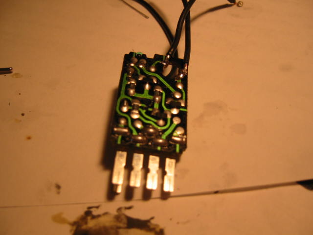
Ok, A/C switch.
-I soldered little wires to the contacts to test them. Ok, I got my digcam back so I'll snap some pics. In this pic, the bulb contacts are in the upper right of the board. the right side is +, left side is -.
That way if I REALLY want to, I can turn it back to stock.Ok, A/C switch.
-I soldered little wires to the contacts to test them. Ok, I got my digcam back so I'll snap some pics. In this pic, the bulb contacts are in the upper right of the board. the right side is +, left side is -.
Last edited by DuB; May 24, 2003 at 06:11 PM.
May 24, 2003 | 05:19 PM
#54
Registered User
Joined: May 2002
Posts: 402
Likes: 0
From: LA, CA
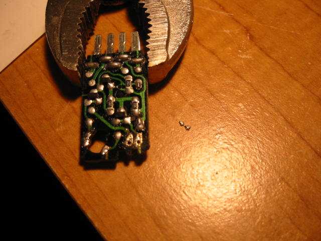
I worked on the LED first.
-unsolder the LED. Heat up both pads and pull the LED from the other side.
-To clean the holes, I heated both pads up, and then smacked the wrench/PCB board combo against the table. Inertia ought to cause the solder to slide right out You can see the two dots of solder in this pic.
-unsolder the LED. Heat up both pads and pull the LED from the other side.
-To clean the holes, I heated both pads up, and then smacked the wrench/PCB board combo against the table. Inertia ought to cause the solder to slide right out
You can see the two dots of solder in this pic.Last edited by DuB; May 24, 2003 at 06:10 PM.
May 24, 2003 | 05:21 PM
#55
Registered User
Joined: May 2002
Posts: 402
Likes: 0
From: LA, CA
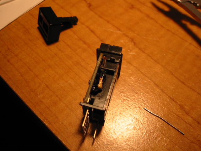
-I used the dremel to enlarge the hole of the piece on the left in this pic. The new LED is a lot bigger.
-The two are initially interlocked. The piece on the right is actually two pieces (you can see the piece in the back is actually another piece), but they snap/slide together.
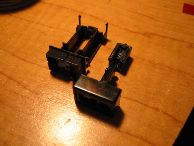
-The two are initially interlocked. The piece on the right is actually two pieces (you can see the piece in the back is actually another piece), but they snap/slide together.
Last edited by DuB; May 24, 2003 at 06:10 PM.
May 24, 2003 | 06:21 PM
#56
Registered User
Joined: May 2002
Posts: 402
Likes: 0
From: LA, CA
DAMNIT. I had buncha stuff written up, but file was too big and erased my text.
-Anyway, bend the legs of the resistor 90 _at_the_base_. It turns out that it makes the LED just the right length and height this way.
-cut the legs to length
-insert in the board and solder in.
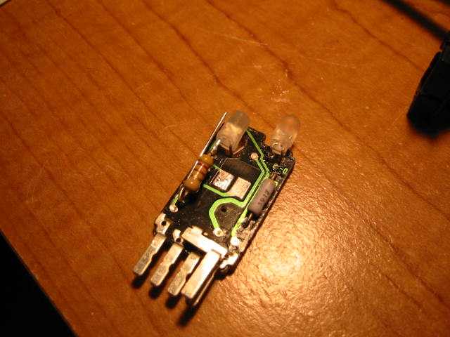
you can see the LED in the upper right of this pic.
The other LED took a bit of creativity. There's no room in the space inside the switch for the resistor, so it has to go on a little space on the outside of it. You might be able to figure out your own solution, but this is how I did mine.
-bend the - leg straight down again and soldered it in place.
-notch the plastic of the switch to let the + leg of the LED slide through.
-solder the resistor on. You can see how I did it in the picture.
-bend the resistor leg back under the resistor. The idea is to have it pass directly under the other leg so that it slides in the same notch in the plastic.
-bend through the hole and solder to the pad.
You can see in this picture that I flattened the tip of the LED that replaced the bulb, and I left the LED that replaced the stock green LED round.
-Anyway, bend the legs of the resistor 90 _at_the_base_. It turns out that it makes the LED just the right length and height this way.
-cut the legs to length
-insert in the board and solder in.
you can see the LED in the upper right of this pic.
The other LED took a bit of creativity. There's no room in the space inside the switch for the resistor, so it has to go on a little space on the outside of it. You might be able to figure out your own solution, but this is how I did mine.
-bend the - leg straight down again and soldered it in place.
-notch the plastic of the switch to let the + leg of the LED slide through.
-solder the resistor on. You can see how I did it in the picture.
-bend the resistor leg back under the resistor. The idea is to have it pass directly under the other leg so that it slides in the same notch in the plastic.
-bend through the hole and solder to the pad.
You can see in this picture that I flattened the tip of the LED that replaced the bulb, and I left the LED that replaced the stock green LED round.
Last edited by DuB; May 24, 2003 at 06:25 PM.
May 24, 2003 | 06:24 PM
#57
Registered User
Joined: May 2002
Posts: 402
Likes: 0
From: LA, CA
This is a bad picture, but if you look really closely, you can see the resistor. There's a bunch of black gunk all over the resistor and its legs which is some paint on electrical "tape" I borrow from my friend. Well, this picture is mostly to show you the little space on the "outside" of the switch.
May 24, 2003 | 06:55 PM
#58
Registered User
Joined: Sep 2002
Posts: 11,199
Likes: 2
From: Pittsburgh, PA
Originally posted by DuB
-To clean the holes, I heated both pads up, and then smacked the wrench/PCB board combo against the table. Inertia ought to cause the solder to slide right out You can see the two dots of solder in this pic.
-To clean the holes, I heated both pads up, and then smacked the wrench/PCB board combo against the table. Inertia ought to cause the solder to slide right out
You can see the two dots of solder in this pic.
You can get it at RS.
May 24, 2003 | 06:56 PM
#59
Contributing Member
Joined: Jan 2003
Posts: 5,377
Likes: 0
From: Houston, TX
Originally posted by DuB
[B]To clean the holes, I heated both pads up, and then smacked the wrench/PCB board combo against the table.B]
[B]To clean the holes, I heated both pads up, and then smacked the wrench/PCB board combo against the table.B]
 May 24, 2003 | 07:02 PM
#60
Registered User
Joined: Jan 2003
Posts: 545
Likes: 0
From: Columbia, SC
Screwdrivers
The little screwdrivers that keep being mentioned can be found at your local wal-mart in the glasses section. I think I saw them in the check-out line in home depot too. They're for fixing glasses and will come in handy if you're doing the blue dash mod.
Zach
Zach


