
FIELD MONITOR UNIT - update w/ pics
 Dec 16, 2009 | 09:13 PM
#1
Thread Starter
Registered User
Joined: Nov 2009
Posts: 79
Likes: 0
From: Olympic City, BC
FIELD MONITOR UNIT - update w/ pics
This Field Monitor Unit write up is for the sole purpose of simplifying the installation and to help understand the ins and outs of the process for those contemplating on doing the same mod. Big thanks to those who did this in the past and have provided invaluable resources and information. Take note that this was done on a '97 4runner, but can also be applied for models thru to 2002. sunroof or non-sunroof models use the same number of wires from the FMU.
here's what i used:
18v impact driver w/ phillips head
flathead screwdriver
ratchet set w/ 10mm socket
angle grinder w/ cut-off wheel
utility knife- used to trim the headliner
2- 25 ft. of 22 awg stranded wire
22-18 awg self stripping tap connector- red color
16-14 awg self stripping tap connector- blue color
5 pcs. of 1/8 dia. x 4ft. long shrink tube- used to insulate the whole wire span
soldering gun/ mini torch
lead...and lots of time and patience
Here goes...
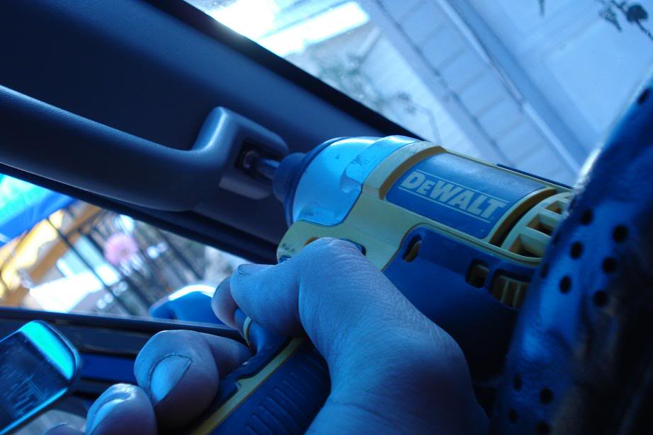
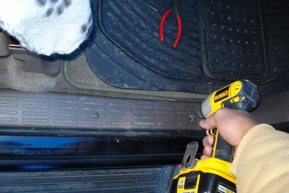
First i removed the grab handles on both sides using my trustee dewalt impact driver, make sure you have the right size phillips bit to eliminate stripping, remember it's held tight with a blue loctite tread locker..
picture shows the bottom screw close to the steering wheel. do both sides.
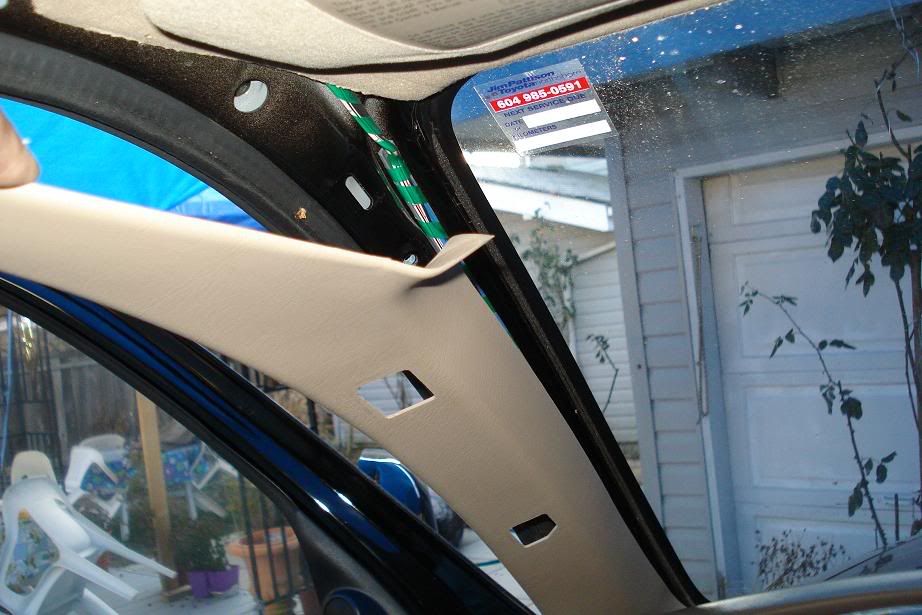
removal of the trim piece is a snap, start by pulling from the rear edge of the front doors towards the dash..they're held by couple of clips and a hook on the bottom part.
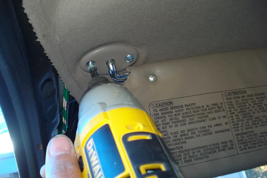
next is to remove both sun visors..it makes it alot easier to run the wires with more room to play with.
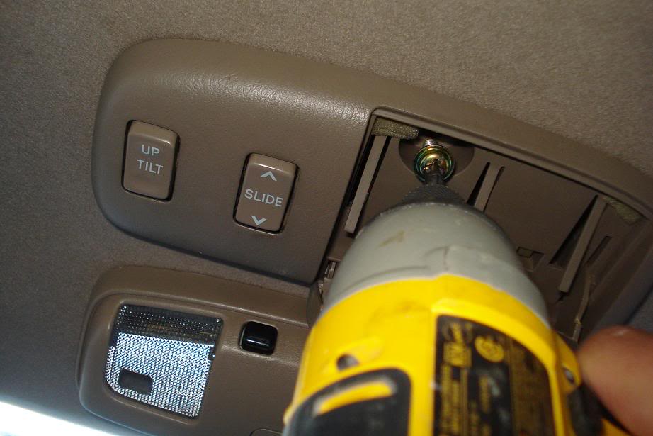
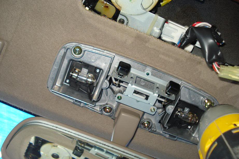
remove the sunroof control by undoing the screw inside of that little compartment, once the screw is removed, push the compartment forward toward the windshield, then pull it down, remember to pull the connector out, this requires pushing down the female connector's tab and then pulling it out at the same time..save the screw for FMU mounting.
to remove the maplights and the rear view mirror, use a flat head screwdriver and pry off the edges of the mirror mount cover. it will then snap off easily by pulling it down. inside are 4 screw holding the actual assembly, remove and retain these screws..only 2 will be re-used to mount the rear view mirror..
next is the removal of the door sill which is held by 4 long phillips screw. remove the sill to be able to remove the kick panel which houses the ABS module. somehow get your fingers under the kick panel then pull it towards you..it should pop off..on my 97 the ABS is on the passenger side kick panel,,,i read that it's on the opposite side on 99's and forward.
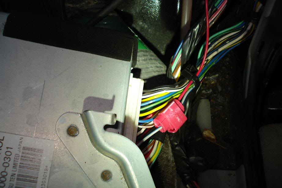
now that the ABS module is exposed, remove the two 10mm bolt to get access to the back of the ABS.
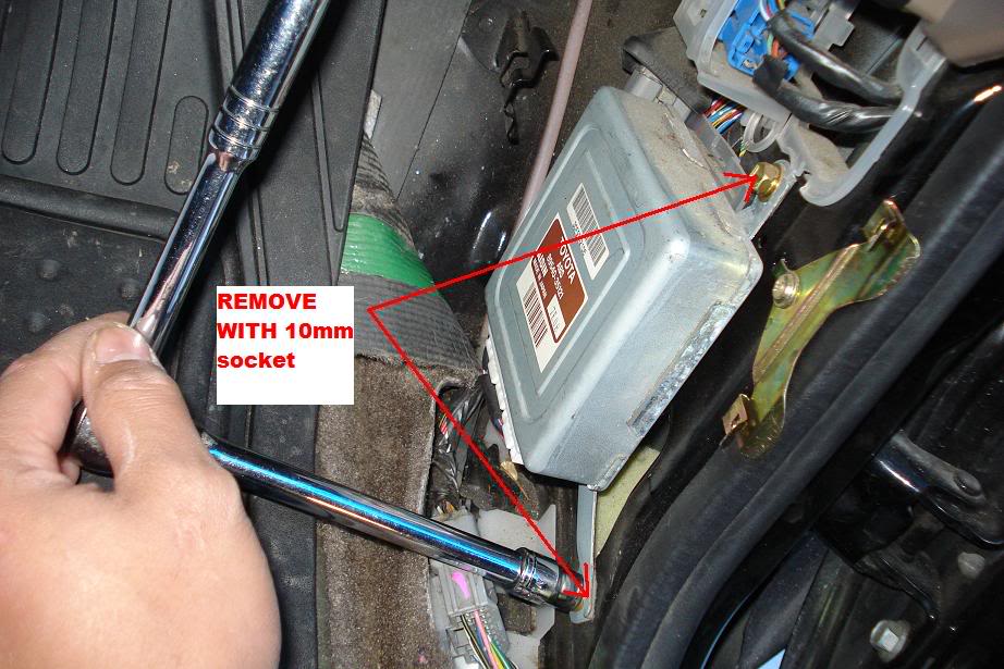
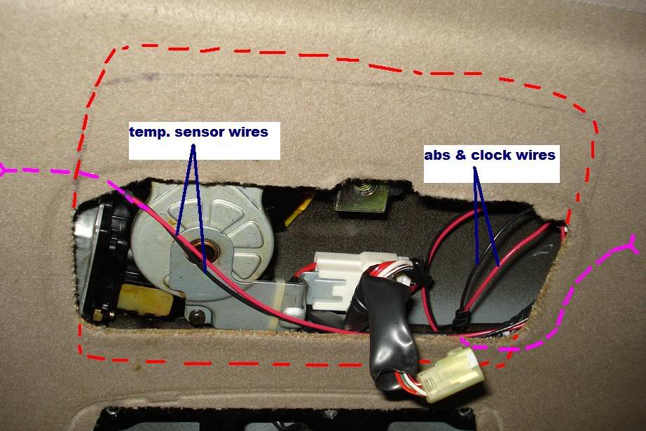
you will then locate the light grey w/ blue stripe colored wire to tap into..run your two wires from the headliner down the passenger side pillar trim. one goes to the ABS and one to the clock wire. Extra care should be taken when fishing the wires using hanger wire..l
Do the same procedure on the drivers side and fish the 2 wires for the temp. sensor.
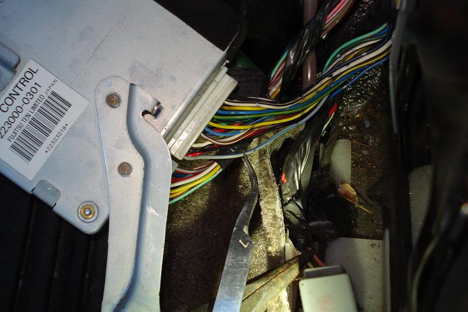
use your red tap connector and tap into the grey/blue stripe wire..top first wire looking from the back of the module(indicated by the tweezer above). make sure of a good connection, zip tie it, put the two 10mm bolts back and you're done with the ABS.
now the clock wire is accessed by removing the front dash trim for the stereo and temperature controls..behind the temp. controls on my '97 are 2 screws holding everything down, plus a couple of hold clips. remove the temp. control cover plate, then the screws and pull the entire dash off, in order to gain full access to the clock wire, few connectors have to be unplugged temporarily like the hazard and the rear window defroster.
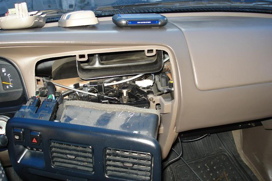
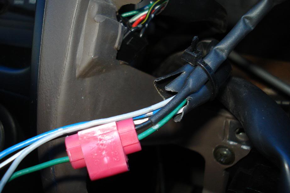
unplug the clock connector and locate the green wire, tap your other wire coming from the passenger side pillar trim into this using your 22awg tap connector..put everything back and were done for the illumination.
Two down..two to go..
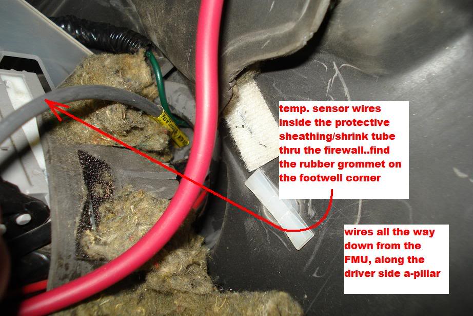
the drivers side is much easier as were only running two more wires for the temp. sensor thru the firewall and towards the sensors final location.
...so again from the FMU's location, two wires go down along the pillar, under the dash and the firewall. use your shortened coat hanger, tape the wires on the other end and punch through the rubber grommet, poke the grommet repeatedly until you know two wires can get through. Pull from the engine bay and if ready, connect the sensor and mount to its location, i left it for last..
i pre-painted the cover and the rear view mirror using Fusion plastic spray i bought from 'Michaels'..closest one i could find.
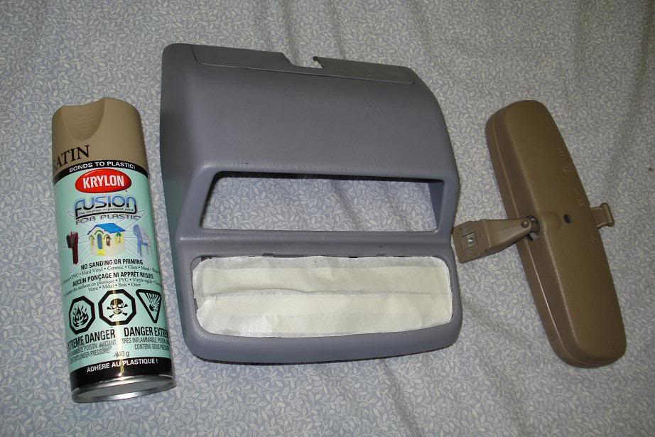
the headliner will have to be trimmed to accommodate the FMU, more than an inch towards the sunroof is needed and a bit towards the windshield(shown with the red dash lines). i suggest pre-fitting the ENTIRE unit, and verify how much will have to be taken off, take time- no room for error here. trim off until the unit sits flat against the headliner and the screw holes line up for installation. tuck all wires so as not to hinder the operation of the sunroof mechanism (if equipped) on your final install.
as for the mirror mount, remove the white male maplight connector from it. then trim off around the screw as shown in the picture below. use an angle grinder or a rotary tool with a cut-off wheel, file the edges of the new mirror mount. re-install the rear view mirror onto the newly cut mount and back to the headliner.
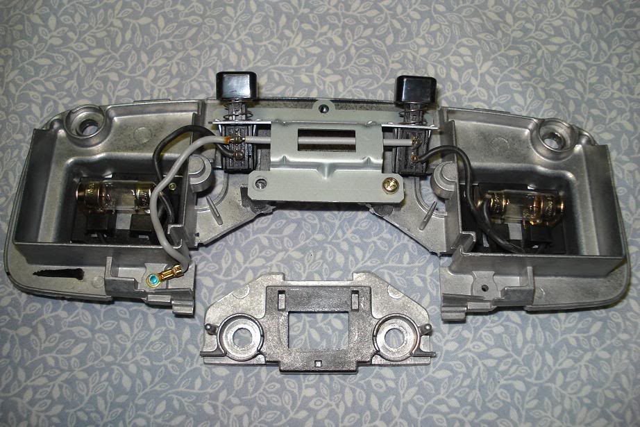
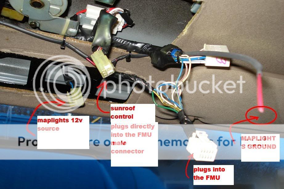
the FMU uses the plug & socket type bulbs whereas the stock uses the fuse style. for the maplights, I elected to use the existing maplight as the 12v source of power, the white male connector on the mirror mount still connects to the existing 12v power wire in the headliner.
See how the rest of the wires from the FMU are connected on the picture below. remove the white connector off the FMU and tap the wires as follow:
blue -temp. sensor
yellow/black -temp. sensor, connecting these two wires to the sensor wires is arbitrary.
green/orange -abs
white/red -switch 12volt(ignition on)
blue/yellow -constant(hot) 12 volt
green -clock(illumination)
white/black -ground, i also used the ground point for the maplights
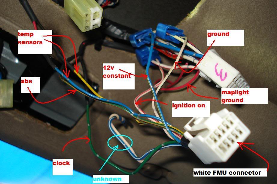
sorted, bundled and zip tied.
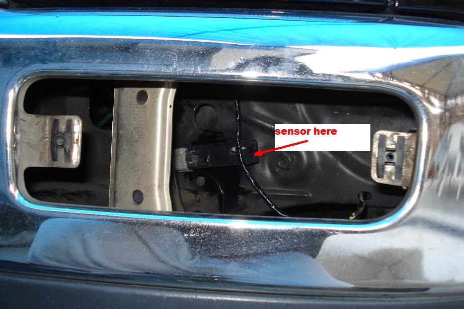
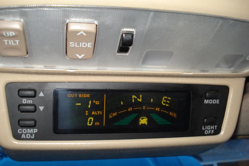
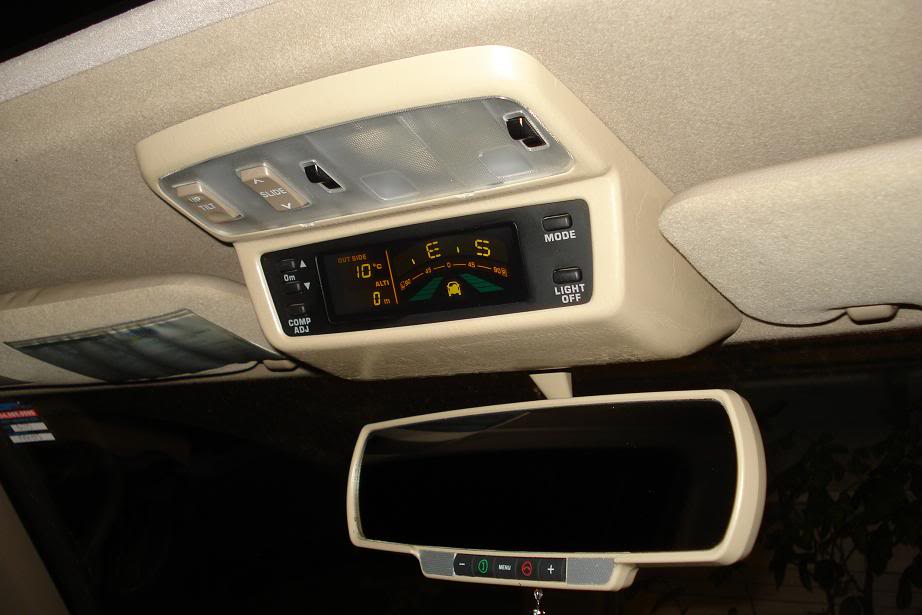
the location of the sensor is just behind to the left of the right bumper lens. i mounted the sensor housing in a way so direct air doesn't hit the sensor itself....Everything works just as they should, the green bars roll as you move forward and reverse, compass directions move in the right headings. i also tried goin' up and the altimeter functions properly..the temperature readings are pretty accurate as per the weather network, turn the headlights on and the FMU screen dims accordingly. sunroof controls are good as well. Light off button to turn the unit on and off.
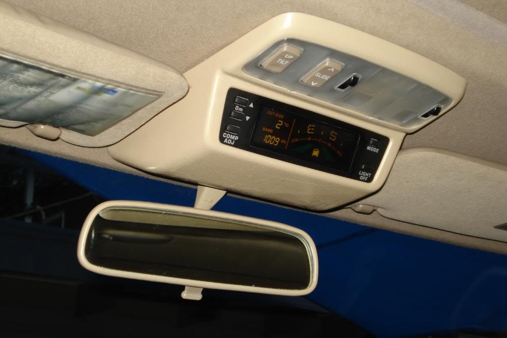
as for our finished product....
Hope this sheds a light in the installation of these nice units.. now i gotta eat!!!!
here's what i used:
18v impact driver w/ phillips head
flathead screwdriver
ratchet set w/ 10mm socket
angle grinder w/ cut-off wheel
utility knife- used to trim the headliner
2- 25 ft. of 22 awg stranded wire
22-18 awg self stripping tap connector- red color
16-14 awg self stripping tap connector- blue color
5 pcs. of 1/8 dia. x 4ft. long shrink tube- used to insulate the whole wire span
soldering gun/ mini torch
lead...and lots of time and patience
Here goes...
First i removed the grab handles on both sides using my trustee dewalt impact driver, make sure you have the right size phillips bit to eliminate stripping, remember it's held tight with a blue loctite tread locker..
picture shows the bottom screw close to the steering wheel. do both sides.
removal of the trim piece is a snap, start by pulling from the rear edge of the front doors towards the dash..they're held by couple of clips and a hook on the bottom part.
next is to remove both sun visors..it makes it alot easier to run the wires with more room to play with.
remove the sunroof control by undoing the screw inside of that little compartment, once the screw is removed, push the compartment forward toward the windshield, then pull it down, remember to pull the connector out, this requires pushing down the female connector's tab and then pulling it out at the same time..save the screw for FMU mounting.
to remove the maplights and the rear view mirror, use a flat head screwdriver and pry off the edges of the mirror mount cover. it will then snap off easily by pulling it down. inside are 4 screw holding the actual assembly, remove and retain these screws..only 2 will be re-used to mount the rear view mirror..
next is the removal of the door sill which is held by 4 long phillips screw. remove the sill to be able to remove the kick panel which houses the ABS module. somehow get your fingers under the kick panel then pull it towards you..it should pop off..on my 97 the ABS is on the passenger side kick panel,,,i read that it's on the opposite side on 99's and forward.
now that the ABS module is exposed, remove the two 10mm bolt to get access to the back of the ABS.
you will then locate the light grey w/ blue stripe colored wire to tap into..run your two wires from the headliner down the passenger side pillar trim. one goes to the ABS and one to the clock wire. Extra care should be taken when fishing the wires using hanger wire..l
Do the same procedure on the drivers side and fish the 2 wires for the temp. sensor.
use your red tap connector and tap into the grey/blue stripe wire..top first wire looking from the back of the module(indicated by the tweezer above). make sure of a good connection, zip tie it, put the two 10mm bolts back and you're done with the ABS.
now the clock wire is accessed by removing the front dash trim for the stereo and temperature controls..behind the temp. controls on my '97 are 2 screws holding everything down, plus a couple of hold clips. remove the temp. control cover plate, then the screws and pull the entire dash off, in order to gain full access to the clock wire, few connectors have to be unplugged temporarily like the hazard and the rear window defroster.
unplug the clock connector and locate the green wire, tap your other wire coming from the passenger side pillar trim into this using your 22awg tap connector..put everything back and were done for the illumination.
Two down..two to go..
the drivers side is much easier as were only running two more wires for the temp. sensor thru the firewall and towards the sensors final location.
...so again from the FMU's location, two wires go down along the pillar, under the dash and the firewall. use your shortened coat hanger, tape the wires on the other end and punch through the rubber grommet, poke the grommet repeatedly until you know two wires can get through. Pull from the engine bay and if ready, connect the sensor and mount to its location, i left it for last..
i pre-painted the cover and the rear view mirror using Fusion plastic spray i bought from 'Michaels'..closest one i could find.
the headliner will have to be trimmed to accommodate the FMU, more than an inch towards the sunroof is needed and a bit towards the windshield(shown with the red dash lines). i suggest pre-fitting the ENTIRE unit, and verify how much will have to be taken off, take time- no room for error here. trim off until the unit sits flat against the headliner and the screw holes line up for installation. tuck all wires so as not to hinder the operation of the sunroof mechanism (if equipped) on your final install.
as for the mirror mount, remove the white male maplight connector from it. then trim off around the screw as shown in the picture below. use an angle grinder or a rotary tool with a cut-off wheel, file the edges of the new mirror mount. re-install the rear view mirror onto the newly cut mount and back to the headliner.
the FMU uses the plug & socket type bulbs whereas the stock uses the fuse style. for the maplights, I elected to use the existing maplight as the 12v source of power, the white male connector on the mirror mount still connects to the existing 12v power wire in the headliner.
See how the rest of the wires from the FMU are connected on the picture below. remove the white connector off the FMU and tap the wires as follow:
blue -temp. sensor
yellow/black -temp. sensor, connecting these two wires to the sensor wires is arbitrary.
green/orange -abs
white/red -switch 12volt(ignition on)
blue/yellow -constant(hot) 12 volt
green -clock(illumination)
white/black -ground, i also used the ground point for the maplights
sorted, bundled and zip tied.
the location of the sensor is just behind to the left of the right bumper lens. i mounted the sensor housing in a way so direct air doesn't hit the sensor itself....Everything works just as they should, the green bars roll as you move forward and reverse, compass directions move in the right headings. i also tried goin' up and the altimeter functions properly..the temperature readings are pretty accurate as per the weather network, turn the headlights on and the FMU screen dims accordingly. sunroof controls are good as well. Light off button to turn the unit on and off.
as for our finished product....
Hope this sheds a light in the installation of these nice units.. now i gotta eat!!!!
Last edited by blcktpgsr; Apr 25, 2010 at 11:14 PM.
Dec 17, 2009 | 04:19 PM
#7
Thread Starter
Registered User
Joined: Nov 2009
Posts: 79
Likes: 0
From: Olympic City, BC
Rock Slide, your write up along with others was very instrumental in my build of this unit. again much gratitude to you guys!..by all means add this to your write up...and thanks to everyone rating & visiting this thread.
Last edited by blcktpgsr; Dec 22, 2009 at 05:11 PM.
Trending Topics
 Apr 26, 2010 | 08:50 AM
#11
Thread Starter
Registered User
Joined: Nov 2009
Posts: 79
Likes: 0
From: Olympic City, BC
Thanks...The green bars are like indicators that scrolls according to the speed and the direction the vehicle is moving, either in forward or reverse, ABS senses that movement.
 Apr 26, 2010 | 09:29 AM
#14
Thread Starter
Registered User
Joined: Nov 2009
Posts: 79
Likes: 0
From: Olympic City, BC
I went with the Yada model # BT30404F-1. I have it set to auto answer so when I receive calls I don't have to press the green button, I just start talking, turns off auto too when conversations over. just one of the convenient features. Auto shuts down so the battery don't drain. I've had it since December and I've yet to re-charge..trucks my DD.
Last edited by blcktpgsr; Apr 26, 2010 at 09:34 AM.
Apr 26, 2010 | 10:31 AM
#16
Thread Starter
Registered User
Joined: Nov 2009
Posts: 79
Likes: 0
From: Olympic City, BC
No it's an independent unit.,I've never tried hooking it up to any accessories for auto turn on/off, not sure it's even possible. Red end call button must be pressed for a few seconds to activate it, when you're away for some time and it doesn't sense any BT signal, it automatically shuts off even if you forget.
Last edited by blcktpgsr; Apr 28, 2010 at 10:17 AM.
May 1, 2010 | 10:22 PM
#18
Thread Starter
Registered User
Joined: Nov 2009
Posts: 79
Likes: 0
From: Olympic City, BC
Thank you Ron..The altitude is in 50 meter increments as you climb up or down. altimeter and barometer is in direct relationship w/ each other, altimeter uses the changes in atmospheric pressure(barometer) in determining altitude changes. Lower the pressure- higher the altitude..something like that. Pressing the mode button toggles between Barometer and Altimeter . If I try manually setting the altimeter it maxes out at 900 meters.
Last edited by blcktpgsr; May 15, 2010 at 09:38 PM.
Sep 13, 2010 | 11:04 AM
#19
Registered User
Joined: Aug 2010
Posts: 242
Likes: 0
Hey Blcktpgsr, great write-up. This has inspired me to try it on my 4runner as I have the same oak interior.
How has the spraypaint held up? I will have to do the same thing when mine comes in. Is the texture pattern of the original vinyl maintained by the paint?
Also, what color is that? I can't seem to find a retailer for that plastic spray paint, so I may have to order it.
How has the spraypaint held up? I will have to do the same thing when mine comes in. Is the texture pattern of the original vinyl maintained by the paint?
Also, what color is that? I can't seem to find a retailer for that plastic spray paint, so I may have to order it.
Last edited by Nelsonmd; Sep 13, 2010 at 11:10 AM.


