
RAD4Runner's 1986 4Runner dlx Build-up
 Apr 3, 2013 | 07:02 PM
#221
I know just enough of electricity to be dangerous, or at least enough on how to get shocked. Done that a few times. It is interesting to see how current flows and gets things to working.
Apr 4, 2013 | 05:36 PM
#222
Thread Starter
Registered User


Joined: Mar 2012
Posts: 7,125
Likes: 681
Apr 4, 2013 | 06:11 PM
#223
Thread Starter
Registered User
Joined: Mar 2012
Posts: 7,125
Likes: 681
Special Service / Diagnostic Tool
DIVIDE AND CONQUER!
The starter solenoid is a good place to divide a cranking issue.
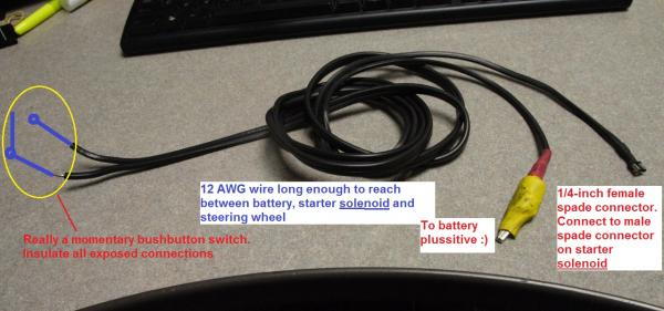
This Special Service Tool Will help you troubleshoot and/or get you started If something keeps power from getting to your starter solenoid coil. I used it to verify what my suspected problem was.
For troubleshooting:
To check solenoid and downstream to starter motor, clutch gear and flywheel,
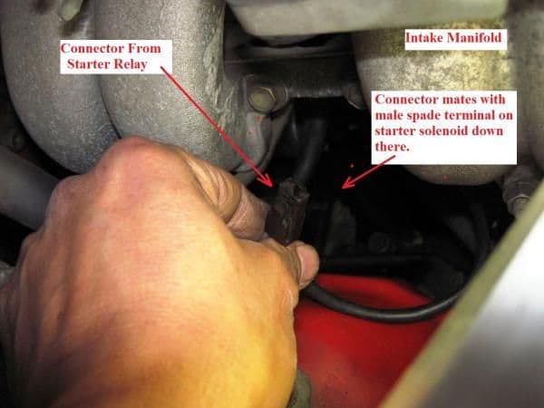
Disconnect this female spade connector from starter solenoid. (This connnector supplies power from starter relay to the starter solenoid)
Connect RAD's Special Service Tool as follows:
Alligator clip to battery plussitive
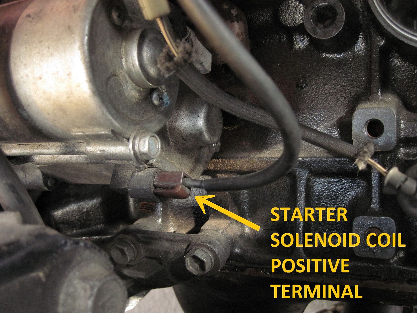
Quarter-inch female spade to male spade on solenoid coil positive where you disconnected wire from in picture above.
Ensure safety - manual trans in neutral or auto in park, your tie not dangling near fans or belts, etc
Push button on. Solenoid should clunk, solenoid contacts will close sending cranking current from superthick wire (connected to battery and screwed-on to terminal on solenoid) to starter motor. Motor should turn, solenoid plunger will actuate clutch, engage starter gears with flywheel gears. You should already know how starter alone or starter engaged with flywheel sounds when turning. See what does not do what it's supposed to do, and go from there.
If all from solenoid and downstream works, troubleshoot from that female spade terminal, upstream to your ignition switch.
To start when you know solenoid and downstream is good, but power is not going to your solenoid coil (i.e., clutch switch defective, starter solenoid defective), or not enough power is getting to your solenoid coil (i.e., wiring flaw explained on my thread), and you have no assistant to jump battery directly to solenoid, do same while attempting to start- at the wheel of course.
If you really have to start the engine while you're looking into the engine compartment by yourself, use in combination with the other Special Service Tool - LOL!
The starter solenoid is a good place to divide a cranking issue.
This Special Service Tool Will help you troubleshoot and/or get you started If something keeps power from getting to your starter solenoid coil. I used it to verify what my suspected problem was.
For troubleshooting:
To check solenoid and downstream to starter motor, clutch gear and flywheel,
Disconnect this female spade connector from starter solenoid. (This connnector supplies power from starter relay to the starter solenoid)
Connect RAD's Special Service Tool
as follows:Alligator clip to battery plussitive
Quarter-inch female spade to male spade on solenoid coil positive where you disconnected wire from in picture above.
Ensure safety - manual trans in neutral or auto in park, your tie not dangling near fans or belts, etc
Push button on. Solenoid should clunk, solenoid contacts will close sending cranking current from superthick wire (connected to battery and screwed-on to terminal on solenoid) to starter motor. Motor should turn, solenoid plunger will actuate clutch, engage starter gears with flywheel gears. You should already know how starter alone or starter engaged with flywheel sounds when turning. See what does not do what it's supposed to do, and go from there.
If all from solenoid and downstream works, troubleshoot from that female spade terminal, upstream to your ignition switch.
To start when you know solenoid and downstream is good, but power is not going to your solenoid coil (i.e., clutch switch defective, starter solenoid defective), or not enough power is getting to your solenoid coil (i.e., wiring flaw explained on my thread), and you have no assistant to jump battery directly to solenoid, do same while attempting to start- at the wheel of course.
If you really have to start the engine while you're looking into the engine compartment by yourself, use in combination with the other Special Service Tool - LOL!
Last edited by RAD4Runner; Dec 30, 2015 at 01:34 PM.
Apr 5, 2013 | 12:37 PM
#227
Registered User
iTrader: (2)
Joined: Dec 2009
Posts: 2,159
Likes: 7
From: Pleasanton, CA - SF Bay Area
I was wondering what the hell that brown plug on my wiring harness was for (putting back together after HG/Head install) - thanks!!
Last edited by Philbert; Apr 5, 2013 at 12:38 PM. Reason: wrong photo
Apr 5, 2013 | 01:23 PM
#228
Thread Starter
Registered User
Joined: Mar 2012
Posts: 7,125
Likes: 681
Apr 5, 2013 | 03:43 PM
#229
Registered User
Joined: Jul 2012
Posts: 2,365
Likes: 4
From: Idaho
Started April Right; Headlight Mod Successful!
To minimize additional parts I rewired the headlight circuit, instead of making an add-on harness.
Stock:
As of 1205 Hrs, 01Apr2013:
Schematic is here (Slumming with MS Paint 'cause I lost Auto CAD license with upgrade to Windows 7 ] :
] :
Notes:
I replaced all thin stock wire from left & right headlight fuses to positive side (pin 3) of bulbs.
Stock wiring all in black. Red "X" are where I cut stock wiring.
Looking at colored wire:
Basically, I cut off stock wiring connecting ground side of bulbs (terminal 1 for low beam, terminal 2 for high beam) from dimmer switch.
Bulb pin 1 (low beam) was disconnected from dimmer contact "HL" and moved to relay contact 87A, This contact now provides ground to pin 1 to turn on low beam.
Bulb pin 2 (hi beam) was disconnected from dimmer contact "FU" and moved to relay contact 87. This contact now provides ground to pin 2 to turn on high beam.
Pin 5/"FU" of dimmer switch connected to negative side of added relay (pin85).
Operation:
When taillight switch is turned to headlight on, headlight relay closes providing +12V to pin 3 of bulb AND positive side of added relay. Normally-closed contact 87A of relay provides ground to pin2, turning on low beam. (In stock circuit, contact FL of dimmer provided this ground and carried the high current.)
When dimmer switch stalk is pulled to "flash" momentarily or pushed forward to turn on high beam, FU contact of dimmer provides ground to negative side of added relay and turns relay on. Contact 87 closes, provides ground to pin 2 of bulb and turns on high beam. (contact 87a opens and low beam turns off.)
Voltage Drop Comparisons:
With Sealed Beam & Engine off
Stock Wiring
High beam indicator circuit TBD after I find junction as noted on schematic.
keyword search H4 conversion, H4 convert
To minimize additional parts I rewired the headlight circuit, instead of making an add-on harness.
Stock:
- Dimmer (combo) stalk switch contacts carry high current for headlights.
- Wires are thin.
- Ground circuit goes on thin wires (AWG 18/20?), from bulbs, to cabin, to dash to dimmer switch, back to engine compartment to ground inside passenger side fender (exactly a convoluted path as 4Crawler describes it), causing a lot of resistance, a lot of voltage drops and reducing voltage that ends up across the bulbs.
- High current (10 Amps on 60-watt high beam, 17 Amps on 100-watt high beams) through dimmer switch contacts will shorten contact life.
As of 1205 Hrs, 01Apr2013:
- Used only one additional part, a 5-pin relay, plus solder & wiring supplies.
- Uses existing headlight fuses
- Upgraded to thicker 12AWG wires, from fuses to ground
- Ground path goes directly from bulb to relay to fender ground, minimizing voltage drops.
- Relay carries headlight current, helping extend dimmer switch life.
- Using normally-closed contact 87A replicates stock circuit for low beam. Even IF relay fails (no power, no ground, or coil open), low beam will still work.
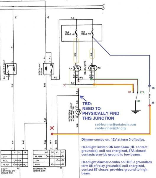
Schematic is here (Slumming with MS Paint 'cause I lost Auto CAD license with upgrade to Windows 7
] : Notes:
I replaced all thin stock wire from left & right headlight fuses to positive side (pin 3) of bulbs.
Stock wiring all in black. Red "X" are where I cut stock wiring.
Looking at colored wire:
Basically, I cut off stock wiring connecting ground side of bulbs (terminal 1 for low beam, terminal 2 for high beam) from dimmer switch.
Bulb pin 1 (low beam) was disconnected from dimmer contact "HL" and moved to relay contact 87A, This contact now provides ground to pin 1 to turn on low beam.
Bulb pin 2 (hi beam) was disconnected from dimmer contact "FU" and moved to relay contact 87. This contact now provides ground to pin 2 to turn on high beam.
Pin 5/"FU" of dimmer switch connected to negative side of added relay (pin85).
Operation:
When taillight switch is turned to headlight on, headlight relay closes providing +12V to pin 3 of bulb AND positive side of added relay. Normally-closed contact 87A of relay provides ground to pin2, turning on low beam. (In stock circuit, contact FL of dimmer provided this ground and carried the high current.)
When dimmer switch stalk is pulled to "flash" momentarily or pushed forward to turn on high beam, FU contact of dimmer provides ground to negative side of added relay and turns relay on. Contact 87 closes, provides ground to pin 2 of bulb and turns on high beam. (contact 87a opens and low beam turns off.)
Voltage Drop Comparisons:
With Sealed Beam & Engine off
Stock Wiring
Low Beam:
Batt: 12.05V, Bulb 11.15V
Voltage drop in wiring: 0.9V
volt drop = 7.5% of battery voltage
High Beam:
Batt 11.94, bulb 10.07
Volt drop: 15.7% of battery voltage!
After Retrofit:Batt: 12.05V, Bulb 11.15V
Voltage drop in wiring: 0.9V
volt drop = 7.5% of battery voltage
High Beam:
Batt 11.94, bulb 10.07
Volt drop: 15.7% of battery voltage!
Low Beam:
Batt: 12.31V, Bulb 12.11V
Volt Drop: 0.2 = 1.6% of Battery voltage
High Beam:
Batt: 12.24V, bulb 11.78V
Voltage drop: =0.46V = 3.75% of battery voltage
Still To Do:Batt: 12.31V, Bulb 12.11V
Volt Drop: 0.2 = 1.6% of Battery voltage
High Beam:
Batt: 12.24V, bulb 11.78V
Voltage drop: =0.46V = 3.75% of battery voltage
High beam indicator circuit TBD after I find junction as noted on schematic.
keyword search H4 conversion, H4 convert
http://revlimiter.net/mods/lowpro.php
shows where to feed power from back to the high beam indicator with a diode
likely im not bein much help but..
Apr 5, 2013 | 04:10 PM
#230
Thread Starter
Registered User
Joined: Mar 2012
Posts: 7,125
Likes: 681
saw this an a page i looked at recently popped up in mind
http://revlimiter.net/mods/lowpro.php
shows where to feed power from back to the high beam indicator with a diode
likely im not bein much help but..
http://revlimiter.net/mods/lowpro.php
shows where to feed power from back to the high beam indicator with a diode
likely im not bein much help but..
the mod on the link is similar to the drop-in H4 harness conversion - relays' are being added. Diode does something else.. something about preventing both High beams and low beams from coming on at he same time.-RAD
Apr 5, 2013 | 04:27 PM
#231
Registered User
iTrader: (2)
Joined: Dec 2009
Posts: 2,159
Likes: 7
From: Pleasanton, CA - SF Bay Area
Hell no! I don't even have the upper intake manifold on yet - wanted to make sure I got all the wiring plugged back in right first

Love your writeups - going to use yours for the H4 harness upgrade soon.
Apr 5, 2013 | 07:40 PM
#232

Symbol is backwards I think. assuming it turns the low beams on with the high beams. *cough*violates FMVSS*cough* all though I did check and it's legal in Colorado to have 4 beams on at once *shrug*
I'll get to this relay mod eventualy, If I go the right day the salvage guy will probably let me have relays. Just gotta show up when he's busy tearing something apart and doesn't want to walk all the way back to the office to write me up a receipt.
 Apr 11, 2013 | 06:57 AM
#233
Registered User
Joined: Apr 2012
Posts: 2,817
Likes: 2
From: Los Angeles CA
Hey Ray. Have you taken before and after shots to aee thw difference with brightness on your headlights? Maybe I might have missed it. But I don't hink so. I'm just curious to see how much of a difference it makes.
Apr 11, 2013 | 07:38 AM
#234
Thread Starter
Registered User
Joined: Mar 2012
Posts: 7,125
Likes: 681
BTW, a drop-in harness will have slightly better performance than my method because you'd be taking power directly from battery, bypassing the main fusible link and network of fuses.
Now I'm ready to install the AutoPals
Apr 11, 2013 | 08:59 AM
#235
Registered User
Joined: Apr 2012
Posts: 2,817
Likes: 2
From: Los Angeles CA
Sorry, Richard, I was not able to take before and after. However, I can really tell the difference. It's not as yellow and dim anymore. Numbers I posted can be used to calculate how much extra power bulbs Re-gained and that can be converted to light output (just don't have time to calculate).
BTW, a drop-in harness will have slightly better performance than my method because you'd be taking power directly from battery, bypassing the main fusible link and network of fuses.
Now I'm ready to install the AutoPals
Apr 11, 2013 | 08:21 PM
#236
Thread Starter
Registered User
Joined: Mar 2012
Posts: 7,125
Likes: 681
Mis-Aligned Clip/Bracket On Overload Spring
Hi I just found this bracket on my left hand side overload spring mis-aligned, and it's probably causing squeaking when I start from full-stop or shift in lower gears.


UPDATED 20130421:
Fixed, guys! Thanks for your ideas.
I merely placed jackstand under frame, jack under rear axlle near spring seat, removed wheel and lowered axle to relive weight on spring pack. Loosened U-bolts and tapped overload spring to line up properly. I did not notice sign that axle shifted on leaf pack. Bracket has obvious wear where overload spring had been rubbing on it (see step in pic below). Overload spring must not have been installed properly in the first place. I hope that fixes the squeak I've been hearing since I did the Zuk.
Last edited by RAD4Runner; Apr 21, 2013 at 07:28 PM.
Apr 11, 2013 | 08:29 PM
#238
Thread Starter
Registered User
Joined: Mar 2012
Posts: 7,125
Likes: 681
Apr 11, 2013 | 08:39 PM
#239
Bfh'd many a starters with a sticky solenoid. I would do just as Phil said. That happened when hitting the perfect mix of relief of the overload in a nasty turn or something. BUT, I only would add that u wanna seee if ur u bolts have become tweeked or backed off.... NOT EVEN CLOSE to likely, but just check.
Apr 11, 2013 | 08:56 PM
#240
Thread Starter
Registered User
Joined: Mar 2012
Posts: 7,125
Likes: 681
Thanks, Mark. Will check that. I also notice that truck now pulls to the left- while it never did for months since I first got her. Maybe happened when I went out to Blair/Little Blair Valley last November.


