When you click on links to various merchants on this site and make a purchase, this can result in this site earning a commission. Affiliate programs and affiliations include, but are not limited to, the eBay Partner Network.
Good stuff! enjoying the build! Question thou, For the 5vz swap did you still need the dash harness from the donor vehicle?
Thanks shoes! You need the dash harness plugs that go into the ECM from the donor as well as the OBDII plug. You'll need to splice these into the plugs from your receiving engine harness so it can plug into the dash harness of receiving vehicle. I don't think I have a picture of the plugs but this is from the toyonlyswaps website.
Whew... been a long time but still alive and the build crawling along. Hit that time of year again where I don't get any time in... that and the wait on a fiberglass bed didn't put any giddy-up in my step... I'll save the story so here's some updates/progress.
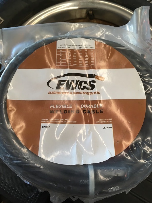
Manufactured the battery cables with 4 gauge welding wire. Very flexible, easy to work with, fine wire, and oil resistant insulation. I bought it off of amazon. Here it is;
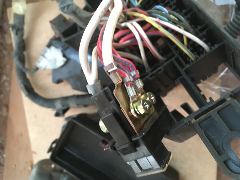
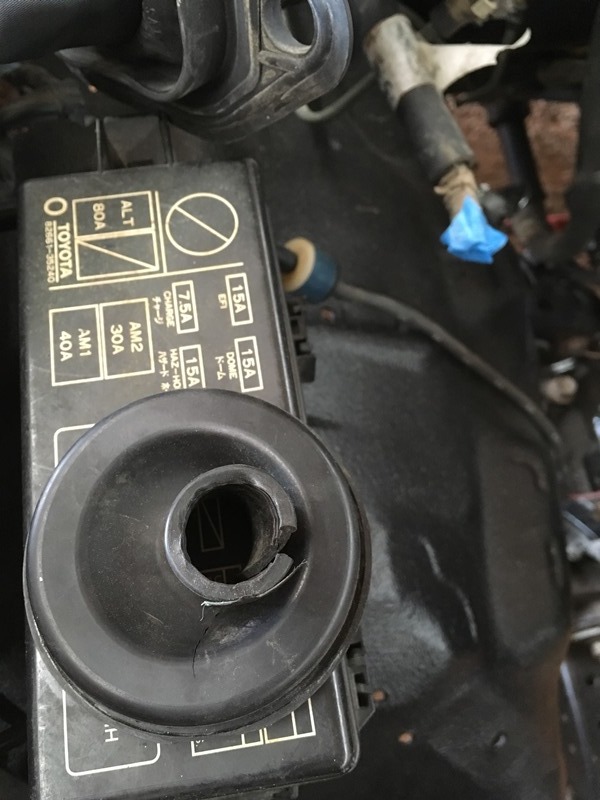
This is really common but for completion this is what I did. Take the fuse box apart and remove the terminal where the old battery cable connects to. The crimp should be integrated with a plate and looks like this once out.
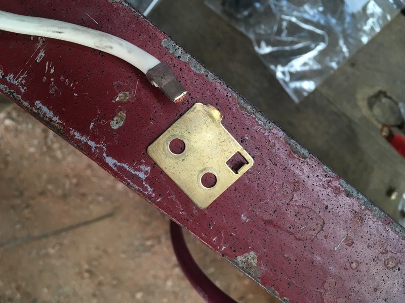
Remove the wires and then break the old battery wire off. My old wire didn't ohm out very well on the Fluke. I can't remember what it was but it wasn't low that's for sure.
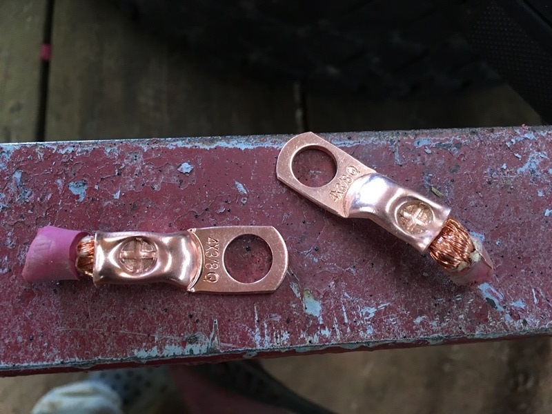
I had problems with the lugs when I crimped them with my Temco lug tool. Many manufacturers don't solder them in and I tried this route. Well inside the fuse box there is a pretty rough 90 degree bend that needs to happen in order for the wire to get fed out of the box. When I bent the cable the copper strands would pull out a bit where the cable experienced tension. I ended up crimping with the lug tool and then soldering to keep everything in place. I didn't take many pics of the process because I figured this was pretty common. Here are a couple of tries where the copper strands pulled out of the lug. I clipped then started over. Insulation fell off the second lug but the first you can see how much pulled from the lug
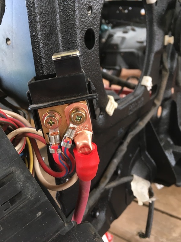
I shrink tubed it with tubing that has an adhesive to try and prevent any oxidation. Take the plate and hook everything back up.
Slap the fuse box together and put it where it belongs. I used 1/2" wire loom for the new battery cable. Just zip tied it to the old loom.
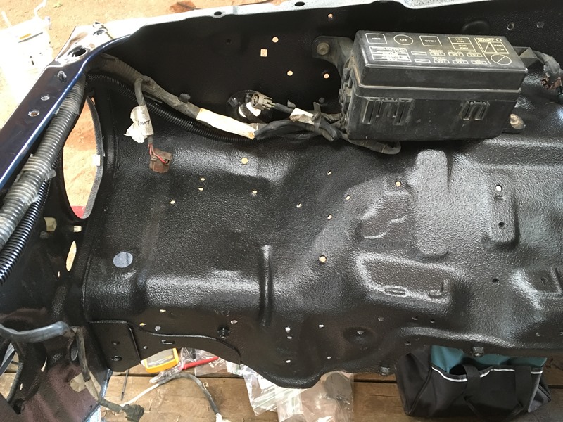
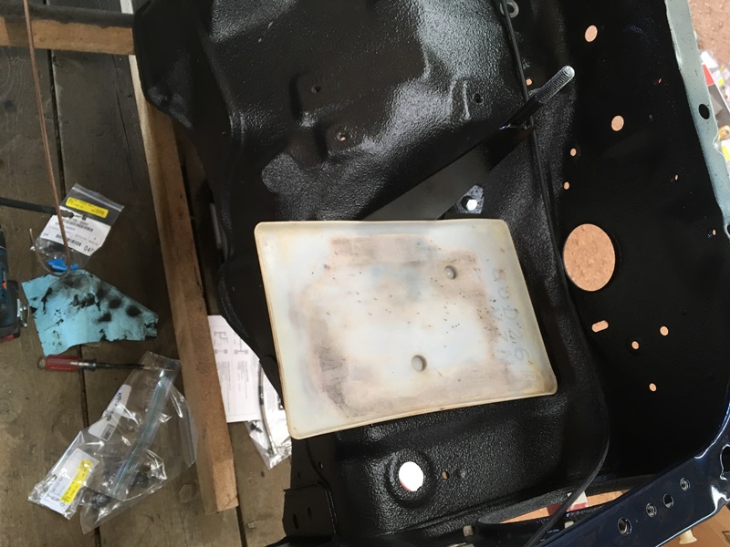
Here's the painted batter box in its place
Plastic tray in
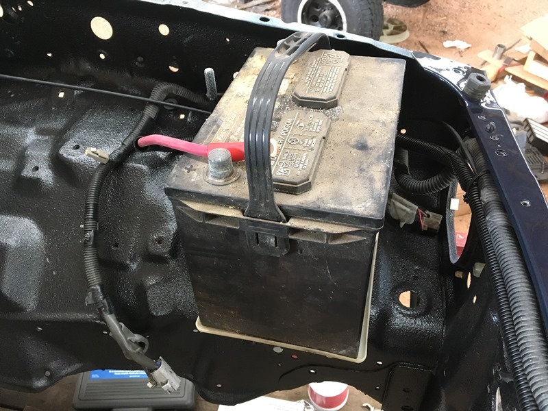
Full mock up
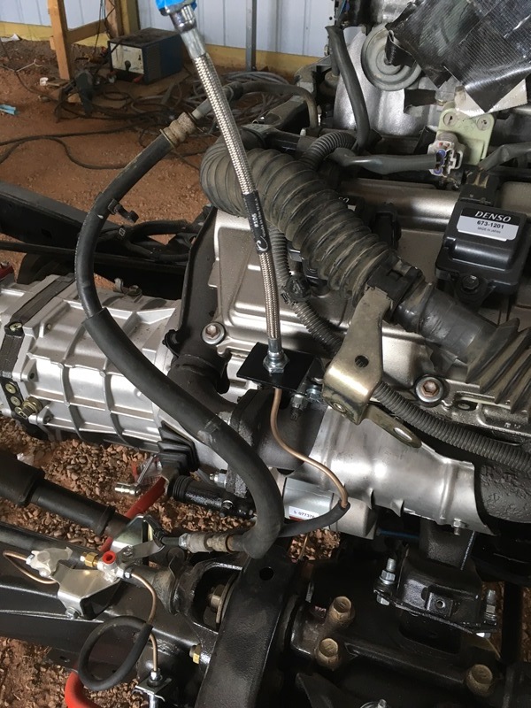
Next was clutch line going to slave. Used some flat stock and did a mock up. Easier with cab off that's for sure.
This is how the lower part looks. I basically made it identical to my stock line
And painted with the stainless line from Marlin Crawler
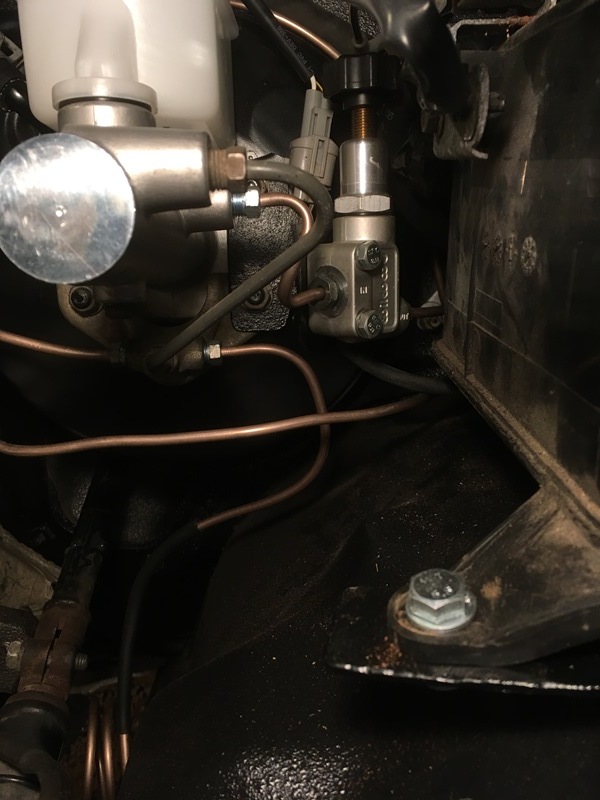
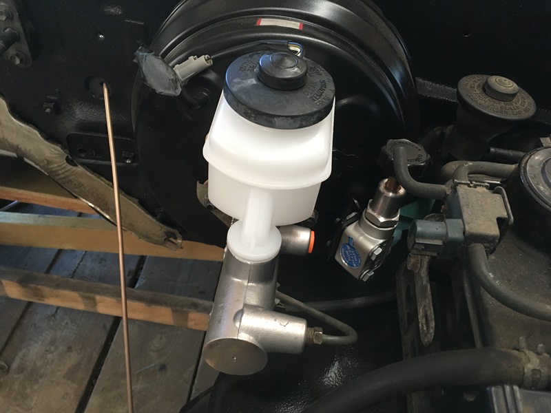
Because I did the disc conversion on the rear, I needed a proportioning valve. I bought one from summit racing with metric fittings. Problem was it's a bubble flare and I didn't see that upon purchase. Took it out of the package and kicked myself for not reading properly Making my own lines so not a big deal, just had to go get the correct nuts. I also needed a larger bore master cylinder so I bought Marlin Crawler's big bore
Willwood 260-12627
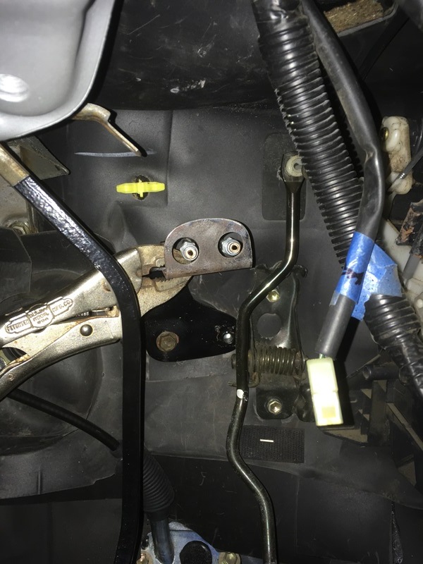
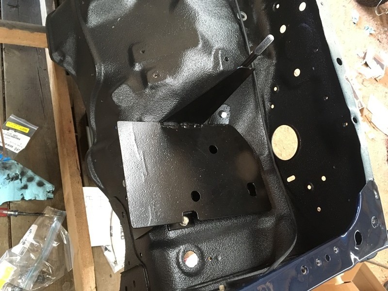
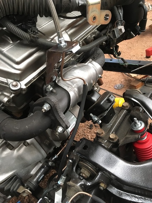
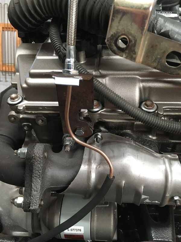
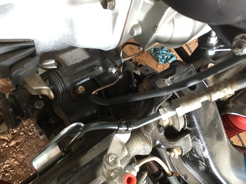
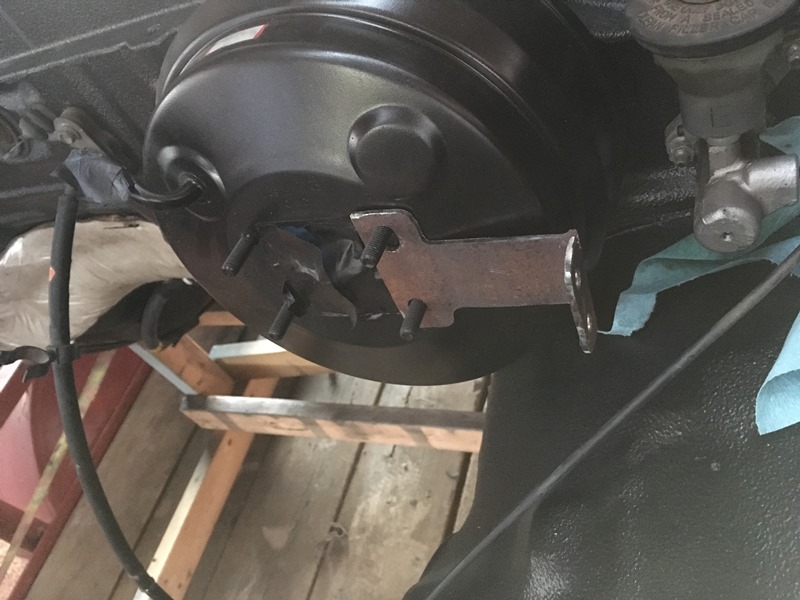
I thought I could get away with a straight bracket without the mockup. This was my initial bracket I made. DON'T MAKE YOURS LIKE THIS!!!! Unless your evap box isn't in the way... Needless to say I had to redo it
I used same bracket but cut it off and welded it on with a goofy angle to make it work. Finished product. Notice how I wised up and placed the evap box in where it will be?
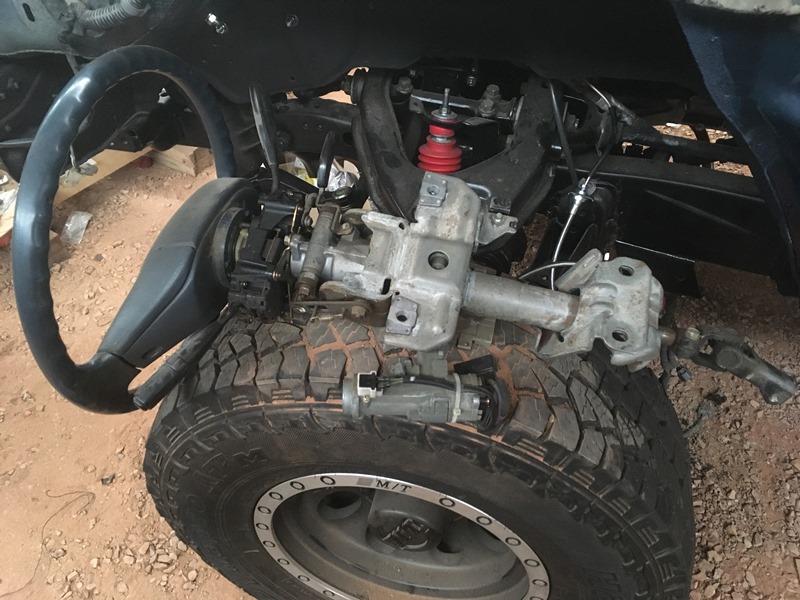
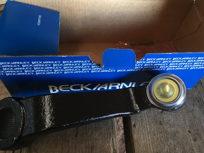
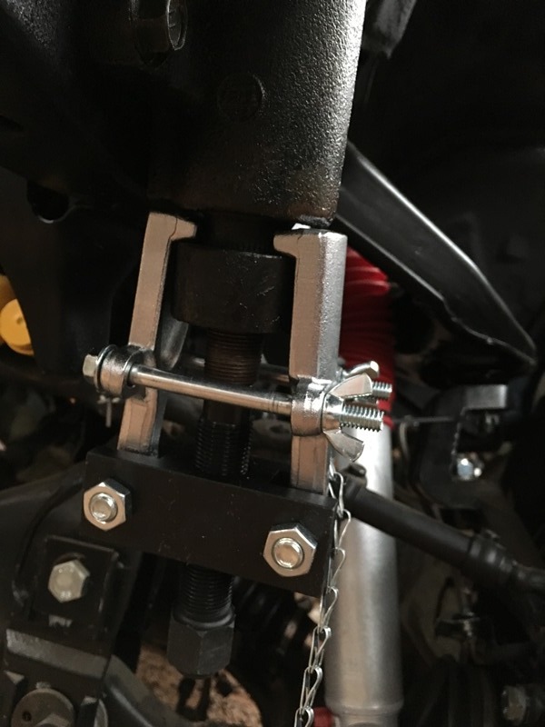
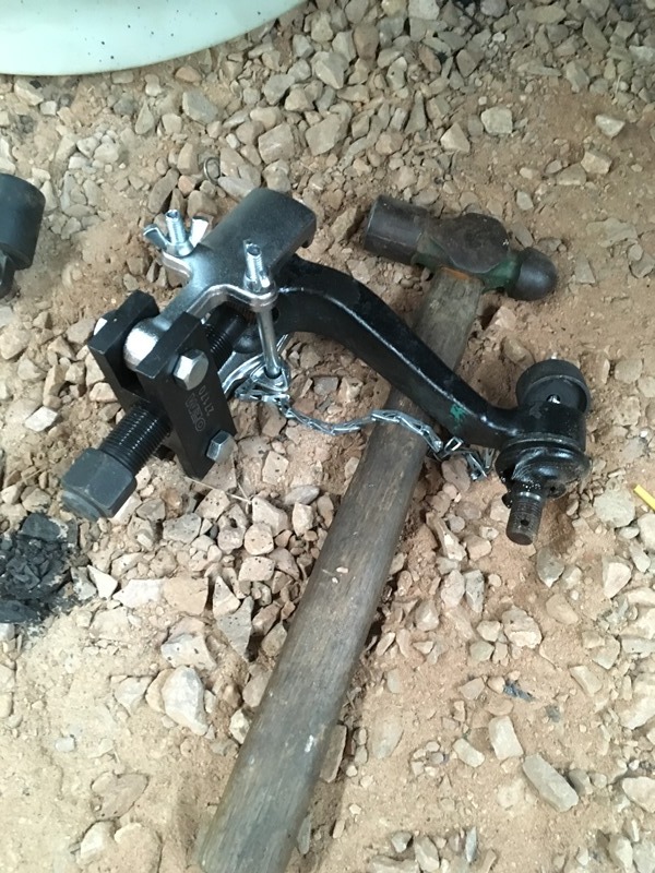
Dropped new pitman arm on. Went through rock auto for a beck arnley to save $$$ but didn't get so lucky. No 555 brand and no idea what it was. I will say I had to buy a tool to get the damn thing off. My gear pullers were about to snap the screw in half.
New tool
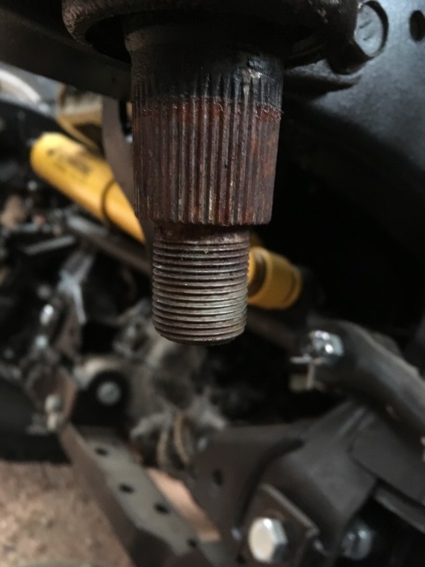
Finally off
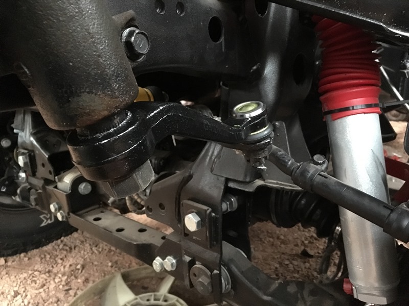
Pretty rusty so wire brushed and lubed up with never-seize....
Nice to see your still at it and with a good update. I like your battery tray you made.. and your bedliner engine bay looks good too! Im in the middle of my 3.4 swap right now, and I think you might have just convinced me to put some new paint into the engine bay.. damn. Two steps forward, one back.
Nice to see your still at it and with a good update. I like your battery tray you made.. and your bedliner engine bay looks good too! Im in the middle of my 3.4 swap right now, and I think you might have just convinced me to put some new paint into the engine bay.. damn. Two steps forward, one back.
Keep it up!
Hey bomberz! As you know it sometimes seems like 5 steps back to every 2 forward I can't count how many times I did something only to tear it apart in order to redo it or I saw a better way to do something. I think the bedliner will be worth it from a durability standpoint with falling wrenches or other tools scraping around in there. I'm feeling good about it so far! Diving into my swap pretty hard right now so stay tuned!
Originally Posted by 84 yota dude
I was actually thinking about this thing recently! Love how you are making it look literally brand new! haha
Thanks again yota dude! Yah my end of year hiatus is always painful when I know there's so much to do. More to come!
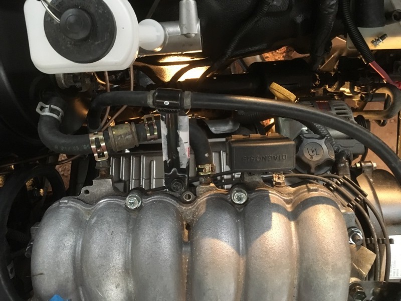
Bought silicon vacuum hose from siliconeintakes.com… Went with black because I didn’t want it to look too loud in the bay. Everything else is pretty bland and “normal” with silver and black so I thought blue and red may look a little out of place in there. I went with the “engine dress up kit” and it should be enough if you don’t do your ADD lines. The ADD suck up all of that diameter length… I’m not done running them but this is what I did so far. I’ll post up the rest of the pictures once they are complete for those that want to reference where the vacuum hoses go
This is rear of engine under manifold. Easy to do without the cab on
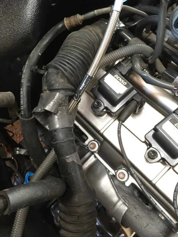
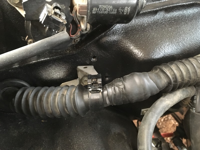
Dropped the cab on and started terminating the engine harness to the ECU. Need to reconfigure a bit in order to get a “factory” look. The metal part on the donor harness needs to be removed and then the rubber needs to be cut back. This is the part I’m referring to. Make sure you cut as little as possible off.
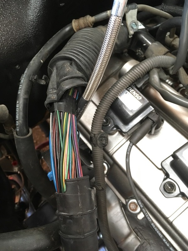
Removed the tape to expose the two rubber loom ends.
Need to shift the harness loom around and stretch it out for complete coverage to the new firewall entrance. I used electrical tape to tape it off
Then took 3M mastic tape to waterproof. Shout out to dntsdad for the mastic tape. I was just going to use self fusing emergency tape which I feel is the same thing…
Take the original 3.0 engine harness firewall plug and make a slit down one side. I needed to do this anyway to get my engine harness plug out of it. I’m sure others had to do the same thing.
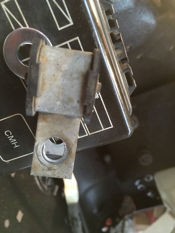
They ECU needs to be set in place in order to figure out how much of the harness needs to be inside the cab. The old mounting brackets need to be removed and fortunately they have tapped holes exactly where the old 3.0 ECU had them. Just need to remove the electrical tape.
Mounts up perfectly but like many others, I had to mount the ECU in upside down. This isn’t ideal due to moisture but I wasn’t about to make any extensions for the engine harness. Hoping I can keep the water out and nothing will fry the board. I haven’t read anyone else complaining so I assume it should be fine.
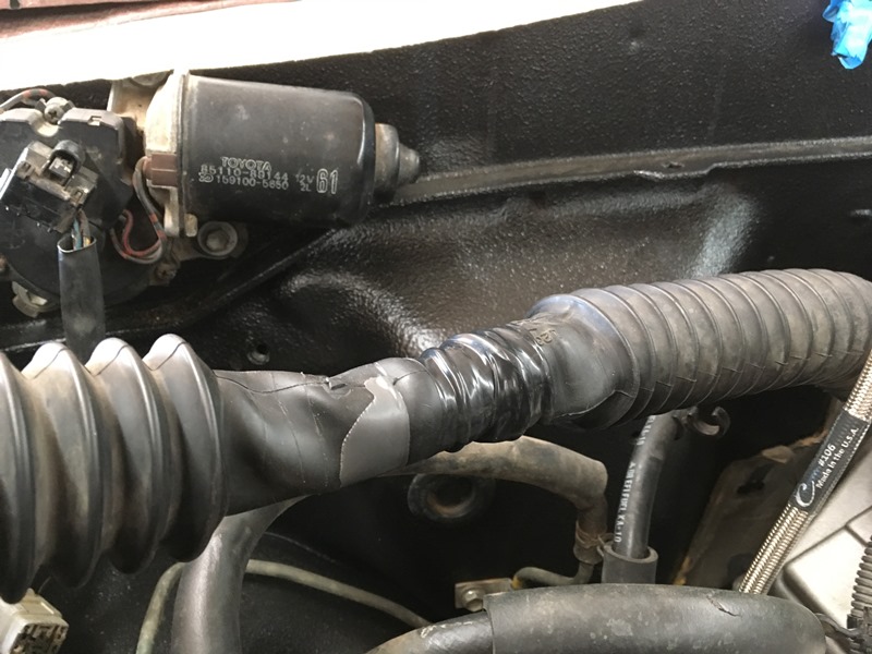
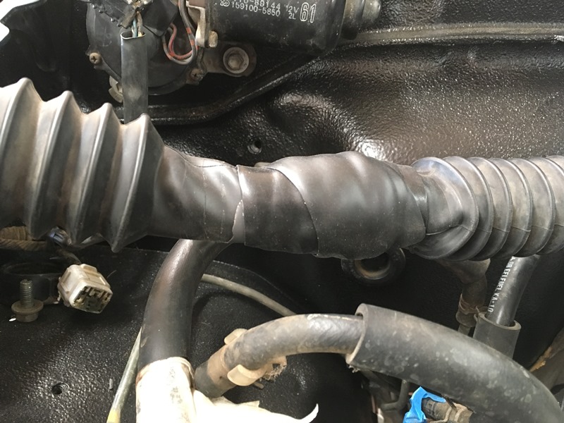
Back to engine bay. I am not using the 3.0 charcol canister so I used those mounting locations on the firewall for the original engine harness bracket of the 3.4…
Combination of mastic and electrical tape on the 3.0 firewall plug
Finished
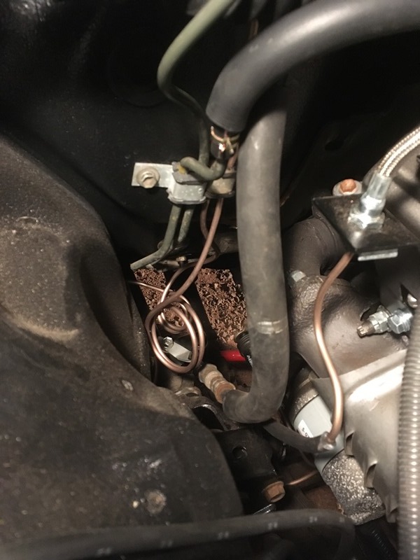
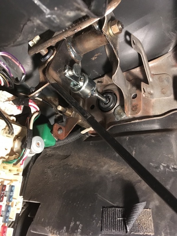
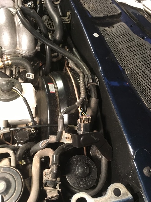
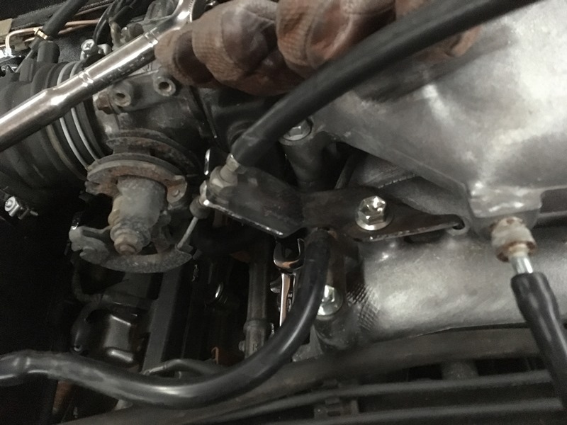
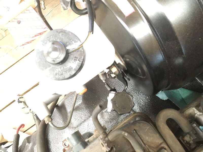
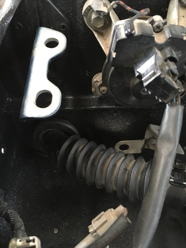
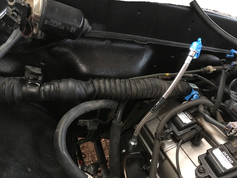
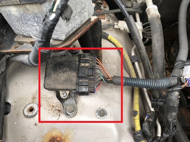
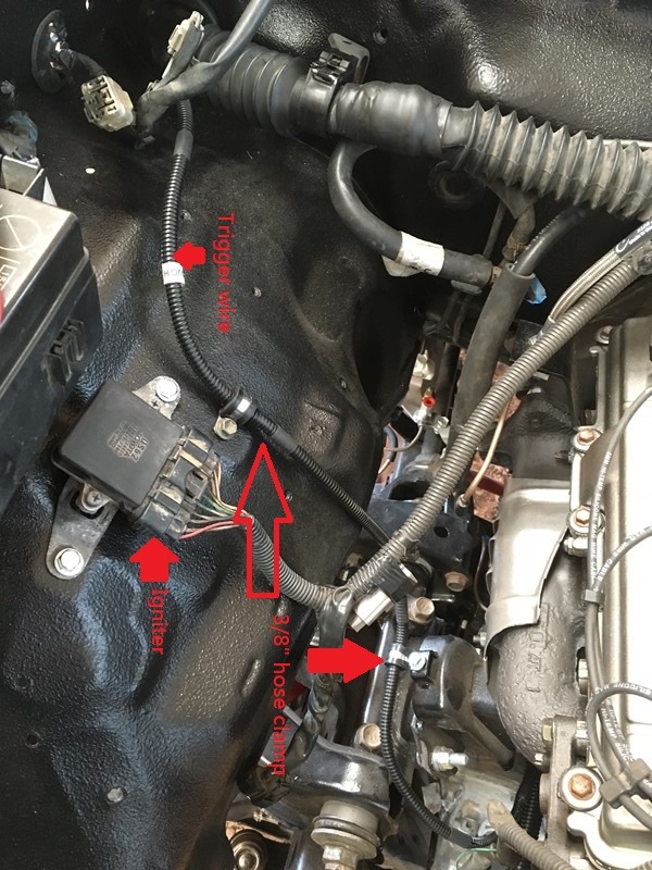
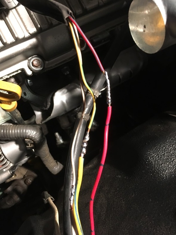
My only concern with what I did is that I may not have given enough slack in the engine bay for engine rock. I may need to remove some slack from the cab but I’ll see how much I’ll need or how it looks when I first start it up. I forgot about the damn trigger wire and the way Toyonlyswaps builds theirs is that it needs to go through the firewall. So I redid the plug to get it through. Below you’ll see how I routed my trigger wire. The ignitor also needs to be swapped over from the donor vehicle. This is what it looks like inside the donor
There are already mounting holes on the pickup so no drilling is necessary. Nuts are tac’d on at those locations too so just need to bend the donor bracket a little bit to make it fit. Trigger wire can also be seen here too
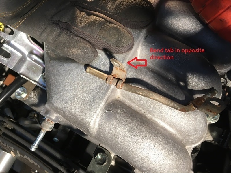
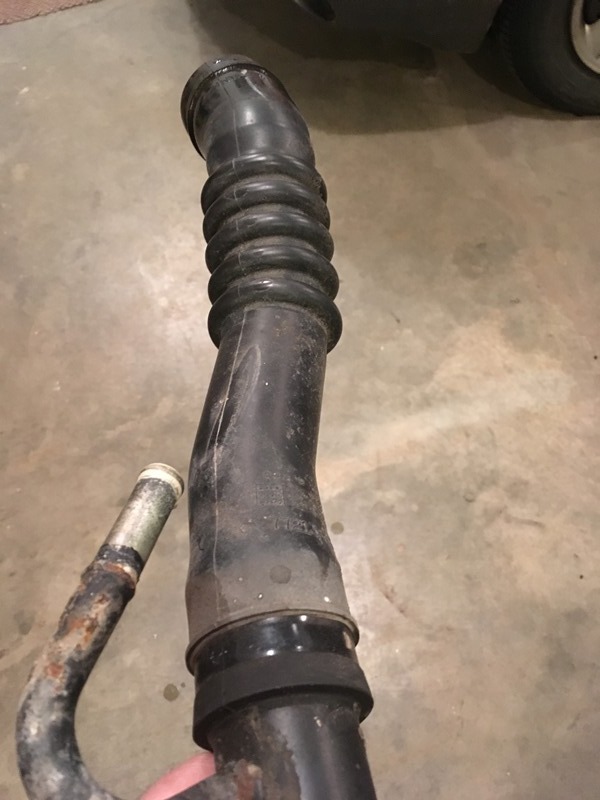
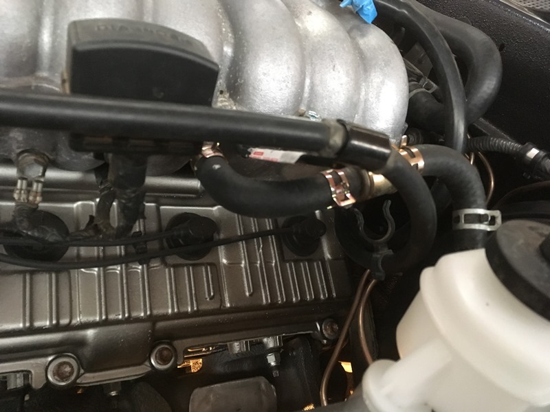
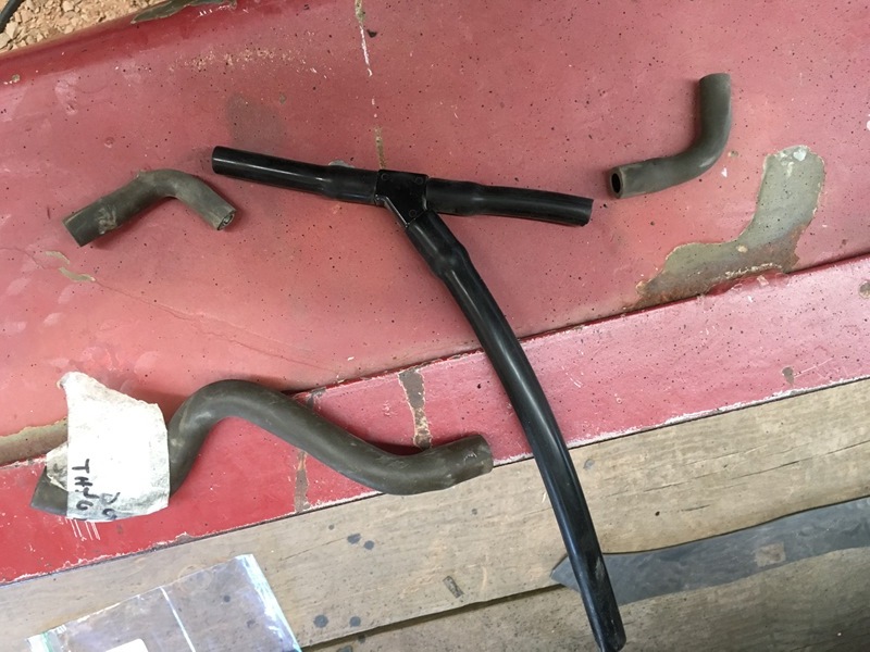
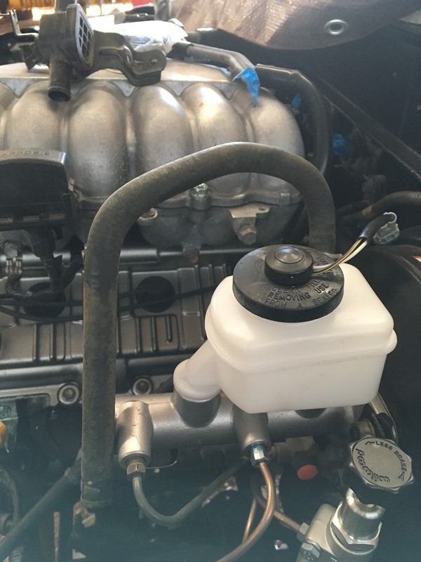
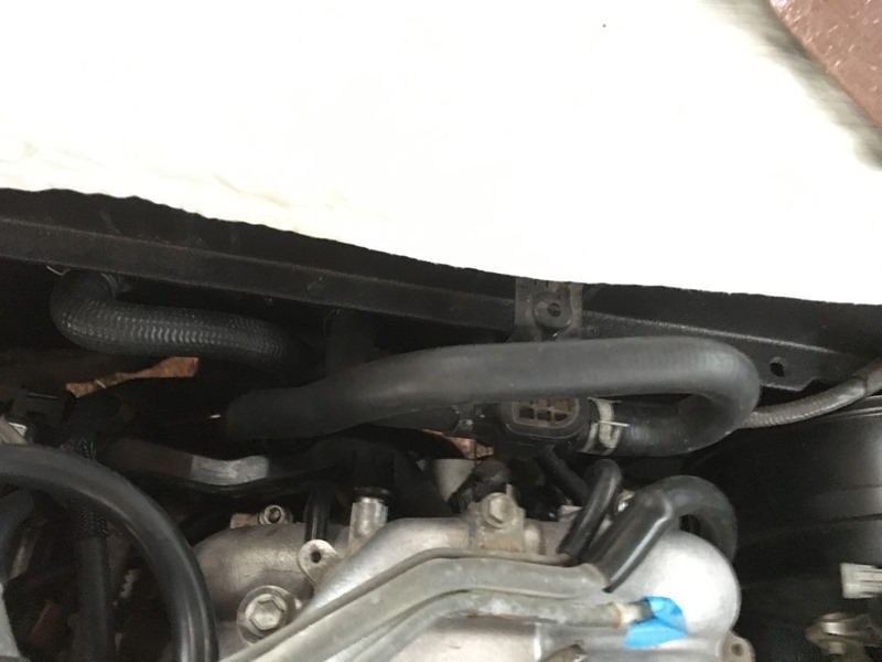
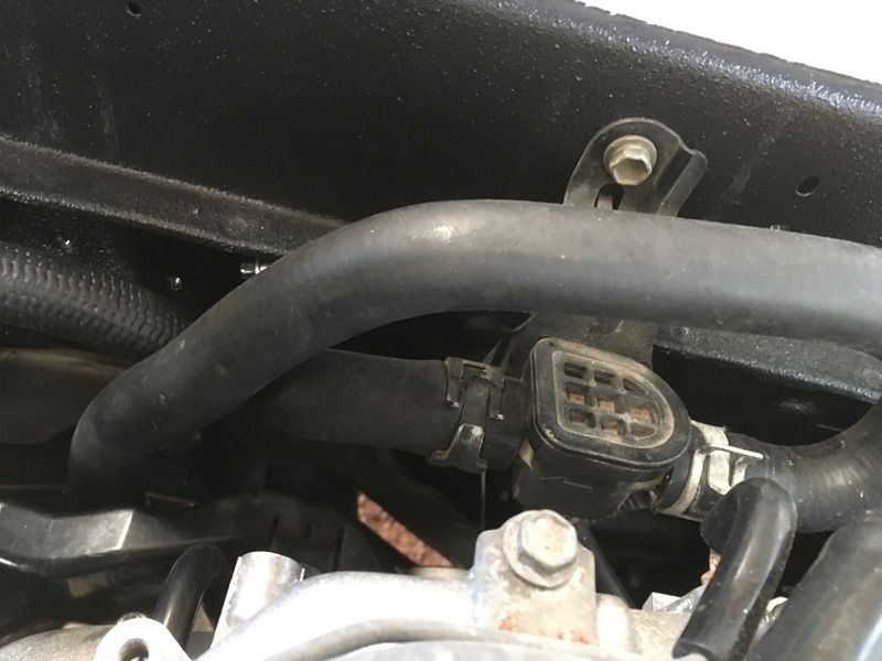
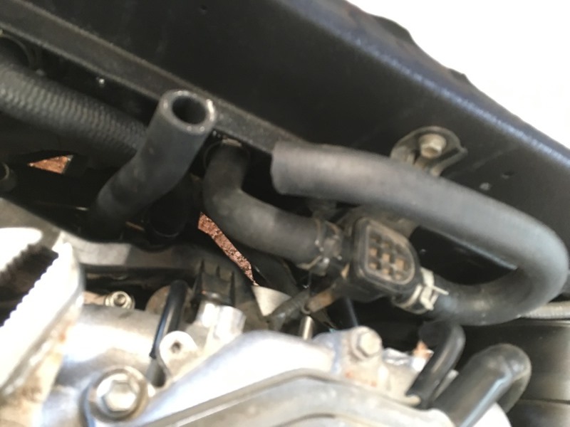
I used the original brake booster hose and check valve for the 3.4. Only the one side of it. I peeled off the check valve and put it in the middle. This is the section I’m referring to
Uncut this is how it looks hooked up
Finished product
With check valve
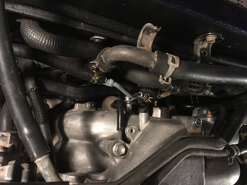
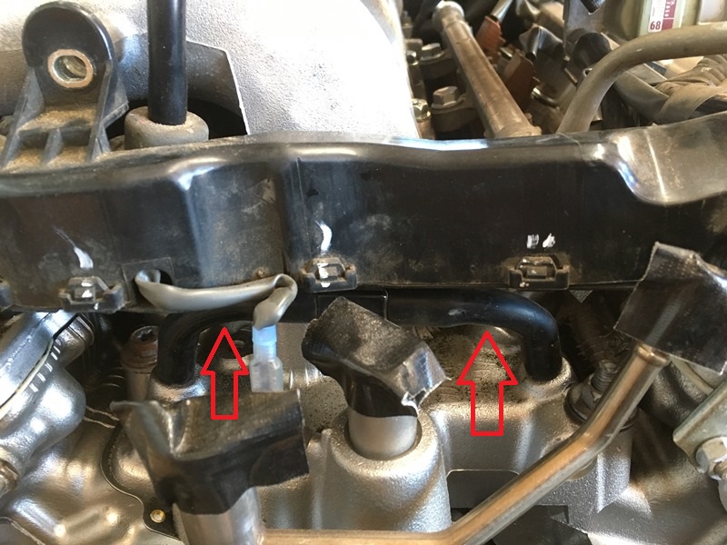
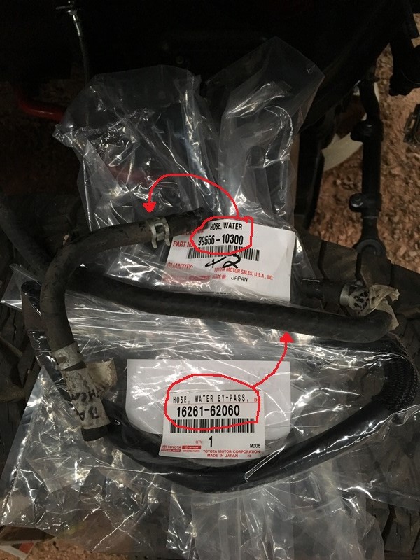
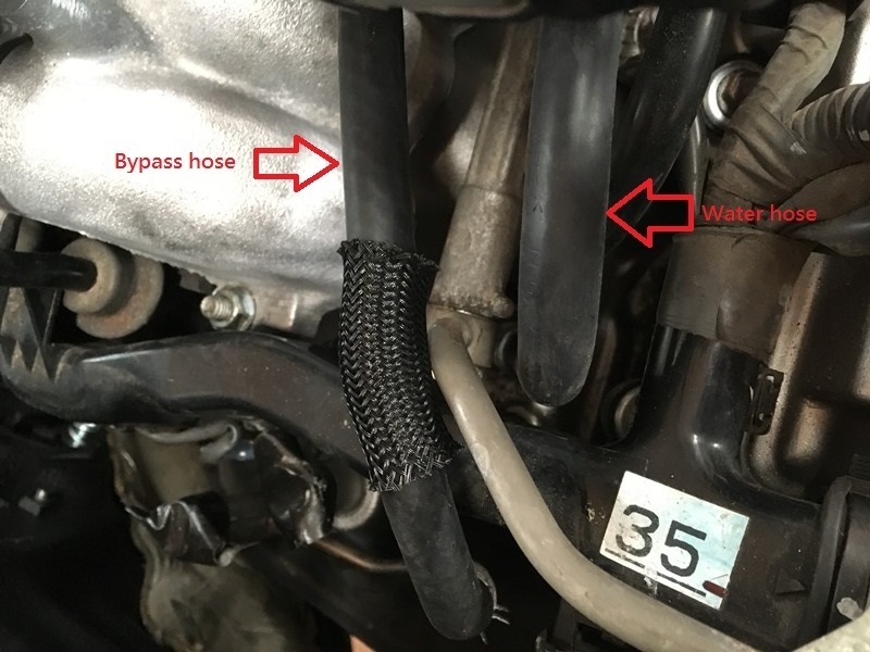
I replaced the water bypass hose and a water hose. I couldn’t find anyone that had anything at the local auto stores. Went factory Toyota.
Bypass hose – 16261-62060
Water hose – 99556-10300
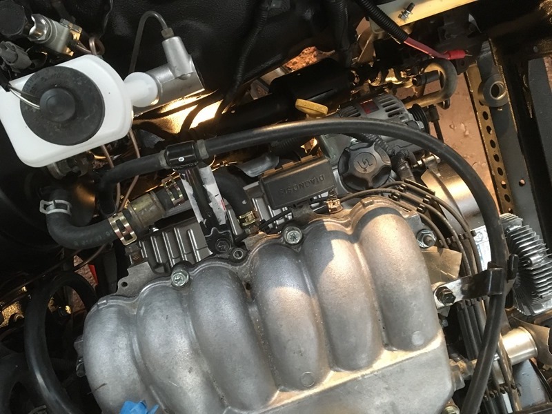
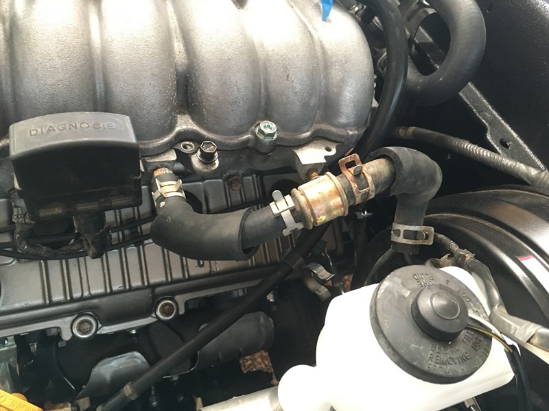
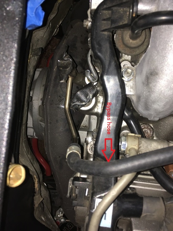
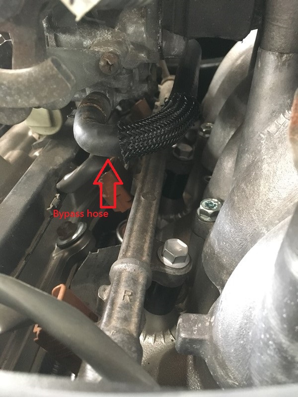
And the installed products. They connect under the throttle body. The high pressure fuel line was rubbing on the bypass so I used the supplied protective sleeve at that point…
Got the heater hoses done too but I'll post that later. Not enough time to do it tonight...
Last edited by duckhead; Jun 28, 2017 at 06:21 AM.
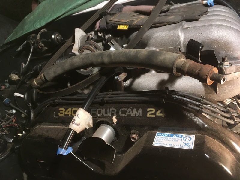
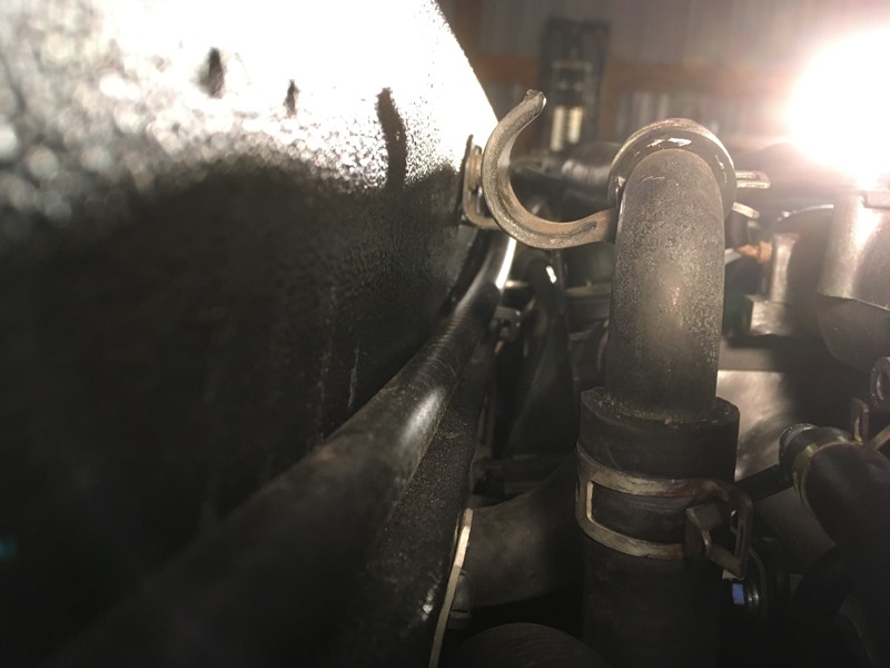
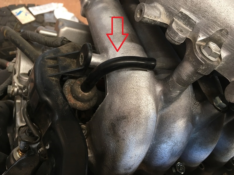
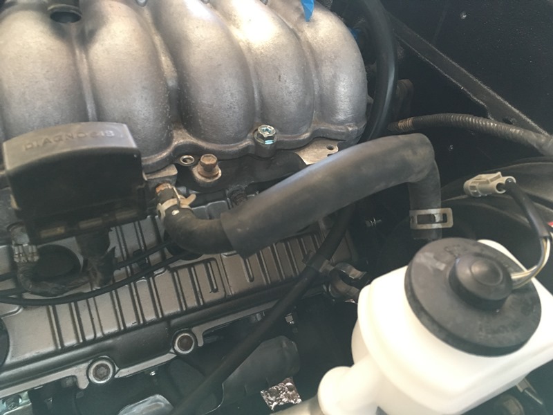
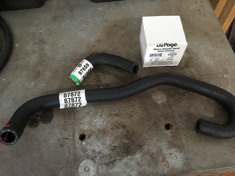
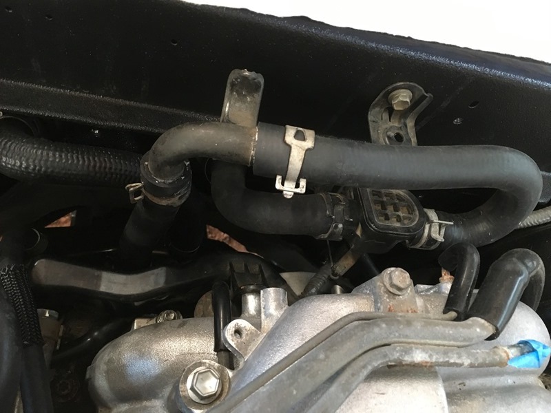
It�s easy to see which hoses are what in this pic. Only problem with the stock hoses is that the 87872 hose rubs as it stands. This can be seen here
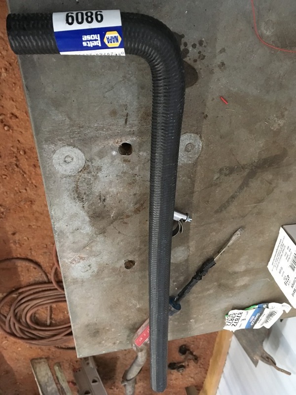
So I cut it at the bend and put in the old 3.0 hardened 90 degree tube. Cut it here
And no rubbing/finished product
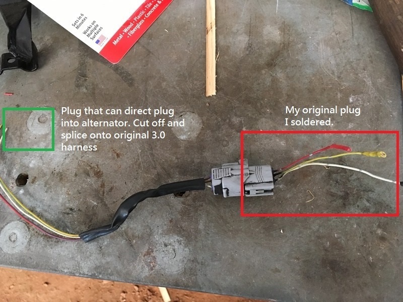
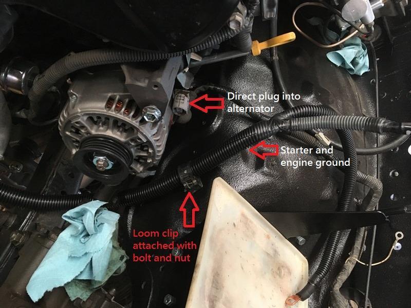
I screwed up on the alternator plug I soldered from before. For some reason I thought a jumper from the original wiring was a good idea. No idea what I was thinking introducing resistance where not necessary with the added plug and extra wire. Many were prolly scratching their heads when I posted that. I decided to do what everyone else probably does with the swap� solder the alternator plug directly onto the 3.0 harness. Cut the other plug off;
Here�s the solder job. I meant to get the plug in the pic but I somehow overlooked what was on the screen. Plug not included�
Also loomed the starter cable and the engine ground cable. Both can be seen in the pic� Along with the actual plug to solder.
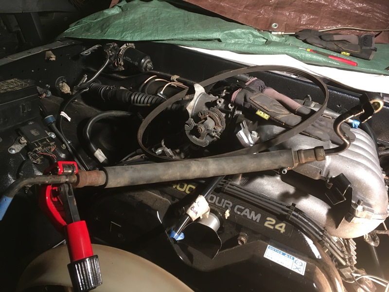
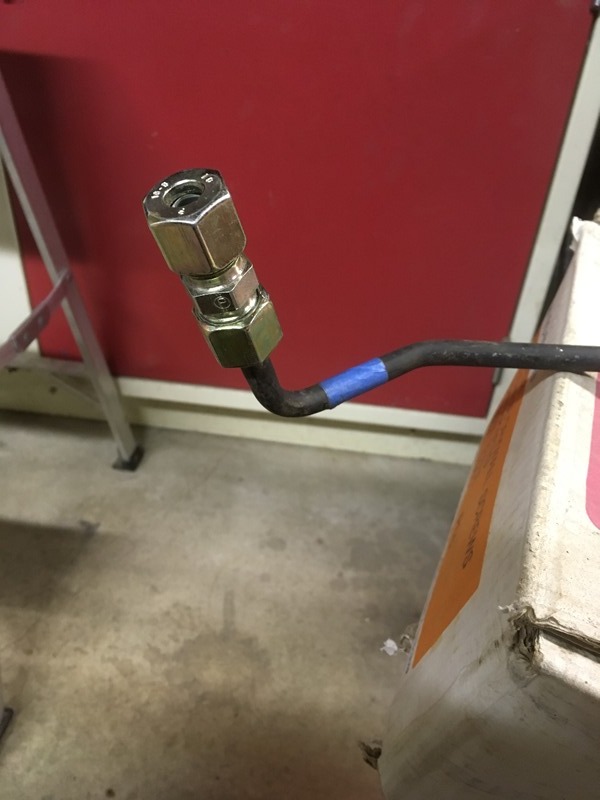
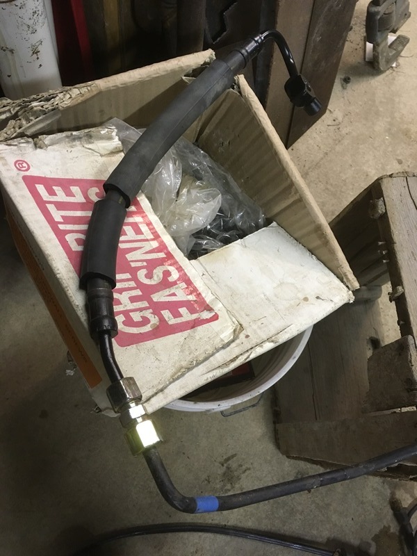
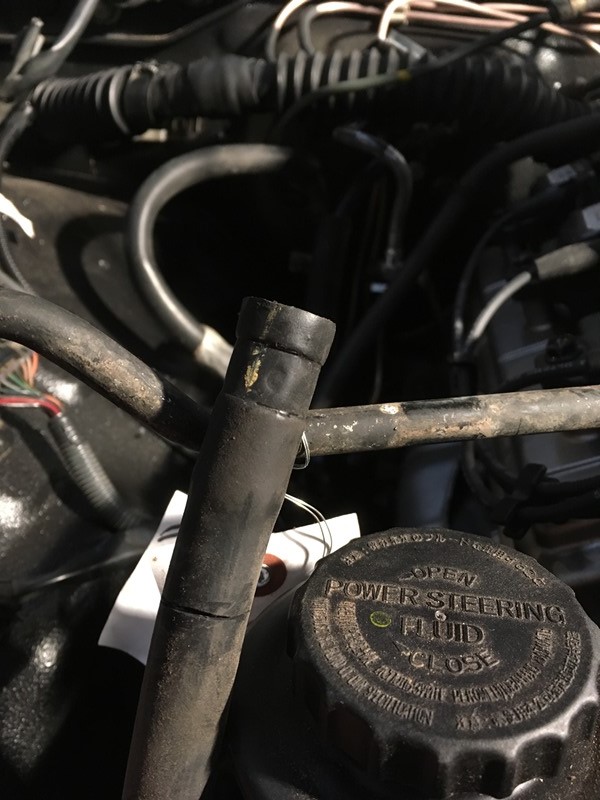
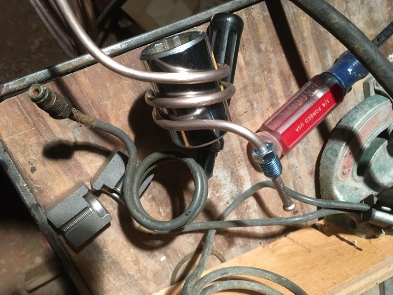
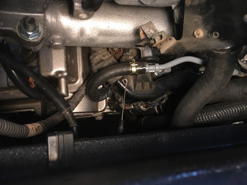
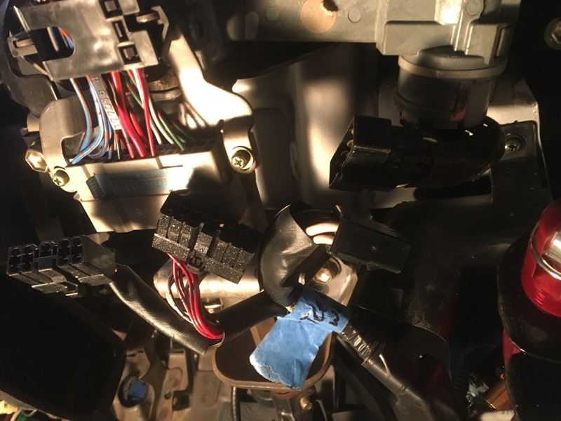
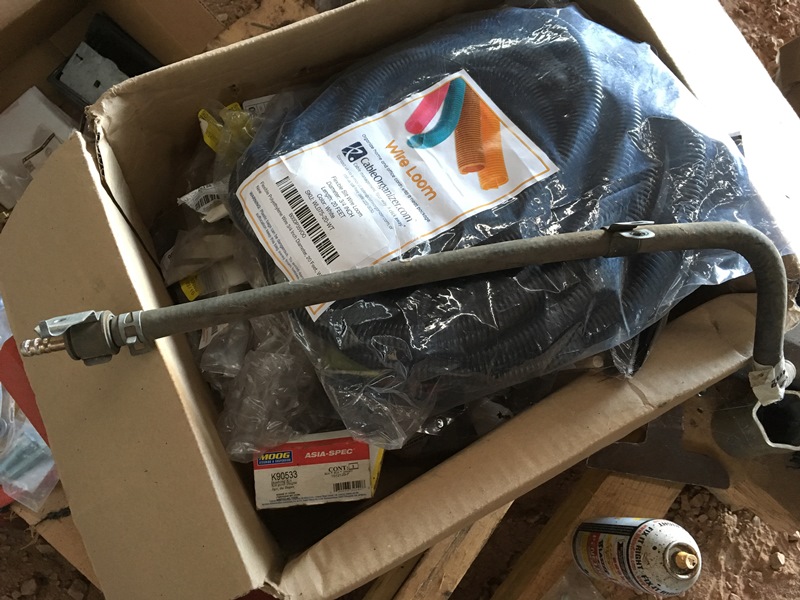
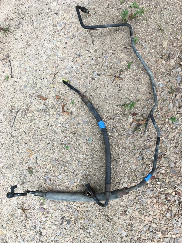
See a lot of people buy new high pressure hoses in their swap. When doing this, they lose the idle up due to the sensor being removed. No one ever complains of any issues going this route but I wanted to keep it. I took it to a hydraulic shop to splice em because I figured they’d have the welders/know how to do it. I’ve read others had good experience doing this. I cut out the banjo end of the 3.4 side and then brought the entire 3.0 high pressure side to the shop. This picture was taken the day I brought it… July 14th. The plan was to have them cut it at the blue tape and put a new barbed hose on there with the 3.4 banjo
I waited… and called… and waited… and called… and…. Waited. I felt invested after a few weeks which turned to a month which then turned to months Felt like I was playing the stock market and refused to sell out… well that and I didn’t have any time to actually do anything with them anyway. They told me custom fittings would have to be made by the manufacturer Parker. I couldn't take it anymore so I picked them up the week of Thanksgiving and they didn’t even touch them Good thing because this helped me out. Regardless, won’t ever go back there again Now that the backstory is over, I went to the ParkerStore. Oh man… They got me setup in under 10 minutes with the not so “custom” part. Best of all, they had a gold color they weren’t supposed to sell. Apparently they were only supposed to sell a silver color. They gave me the compression fitting for free Soooooo… If anyone wants to go this route, you need this part number;
G10SCF (Parker is the manufacturer)
The guys at the store said it costs approximately $10. Big savings and you get all of the features! If you’ve ever done any compression fitting you will have no problem. It’s all the same… Spec sheet states pressures up to approximately 9000 psi so shouldn’t have an issue with this application.
Get your tube cutter out and cut where you want to splice. Make sure you pick a straight section. It won’t work on a bend.
3.0 line chopped
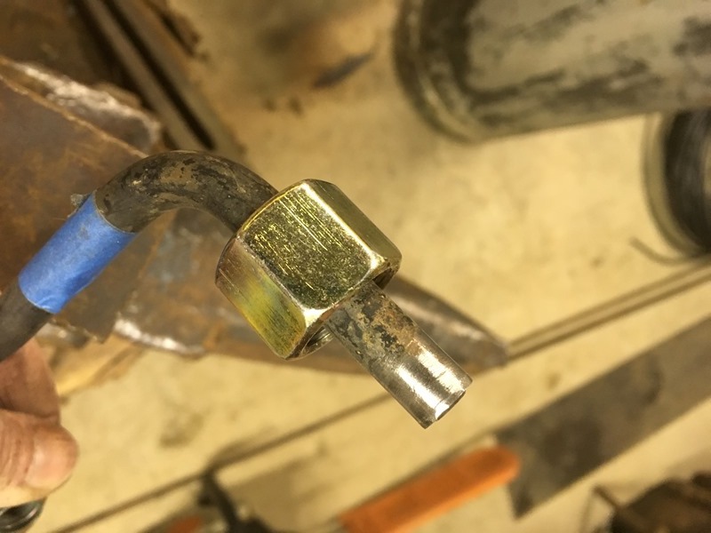
Take the 3.0 line you want and wire brush a section where the ferrule will bite into the tube. You’ll likely need to do this just to get the ferrule on. Pic without the ferrule;
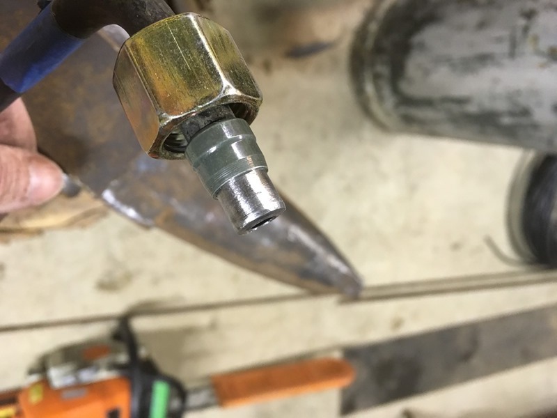
Pic with ferrule
Get your wrenches out and put it together good and tight. Ignore the other end, this side will have the 3.4 tube and 3.4 banjo.
Do the same thing to the 3.4 side and put it all together. I put the original heat/protective insulators on it. You will likely have to cut it in half because the 3.0 barbed hose has a metal fitting in the middle. This will rip and cause the insulator to get hung up on it. I had no choice but to cut it in half to get it off.
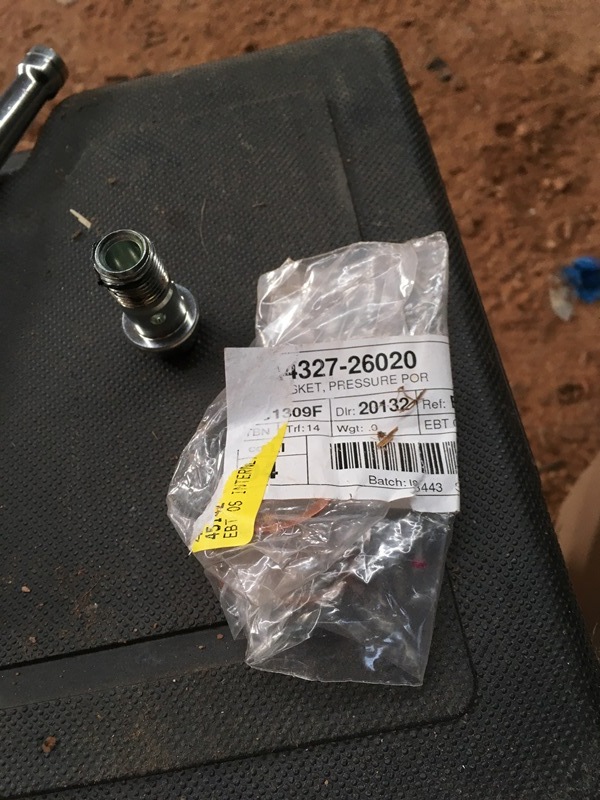
High pressure side I put a new banjo with a copper gasket.
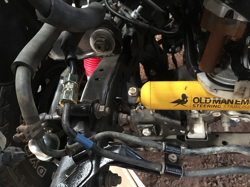
Here are both tubes basically installed. Keep in mind when you go the compression fitting route, orientation doesn’t matter as you can loosen it a little bit and spin it to wherever you want.
Looks factory
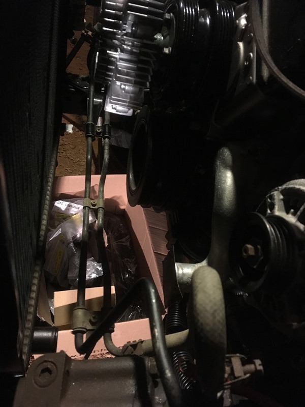
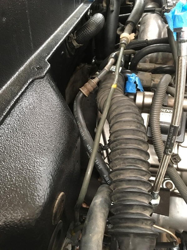
This was initially how much I cut off the return line. There was honestly a lot of slack. I took off more but didn’t take a picture of how much. I cut off nearly up to the end of the stock insulation around the power steering pump side of the return line.
This picture gives a better idea how much I cut off.
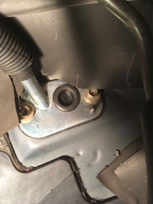
Really easy job and should save you quite a bit of money as opposed to having someone else weld, braze, or fabricate a new high pressure line. Assuming it works as advertised The old emergency brake plug I made with self fusing emergency tape was replaced with a 20mm rubber plug. I think I bought a bunch off of ebay for a few bucks.
I got the brake lines done too but it's too late to add that. That was a pretty involved project. Maybe tomorrow...
I needed to make quite a few brackets for all of the lines. Many of the pics were taken when everything was done so things may be out of order. Just trying to give others considering the swap an idea for hose and line placement. I don�t think I saw many do this in their swap threads so hope it helps.
The old clutch bracket put the SS flex line up against the engine harness. I didn�t want any rubbing so I made the clutch line bracket so it went higher than the old one to get it above.
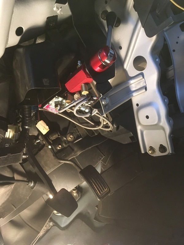
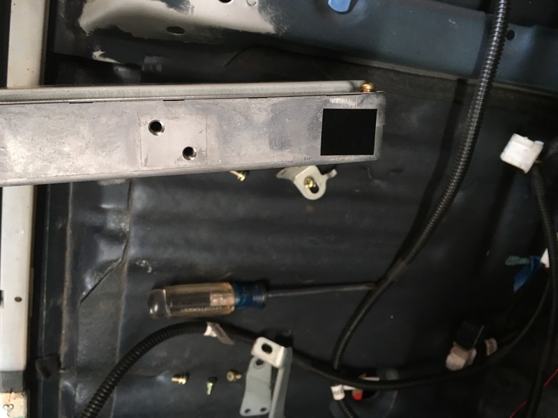
I did do the disc swap so I don�t have a parking brake anymore. I wanted to do the T-case e-brake but with my chain driven case this isn�t an option so I opted to use a line lock and splurged on a Mico brand one. This is a factory image from google. I didn�t take a pic of it with all of the components
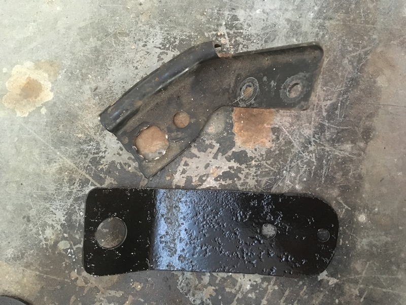
I know a lot of guys use Jamar line locks but the results/reviews are incredibly mixed. Many report failure and for the safety of myself and the truck, I felt the Mico investment was worth it for a quality part with a hell of a reputation. Personally never had an issue with Mico when I�ve used them. This lock is large� Mostly due to the low pressure alarm on the tail end of it. If you can find an older model it didn�t have this. I�m not going to splice into my horn wiring yet but may in the future so this feature will go unused for now in this build. I wanted the lock in the same place as the stock e-break handle. This is the bracket I made using the old mounts for the stock bracket.
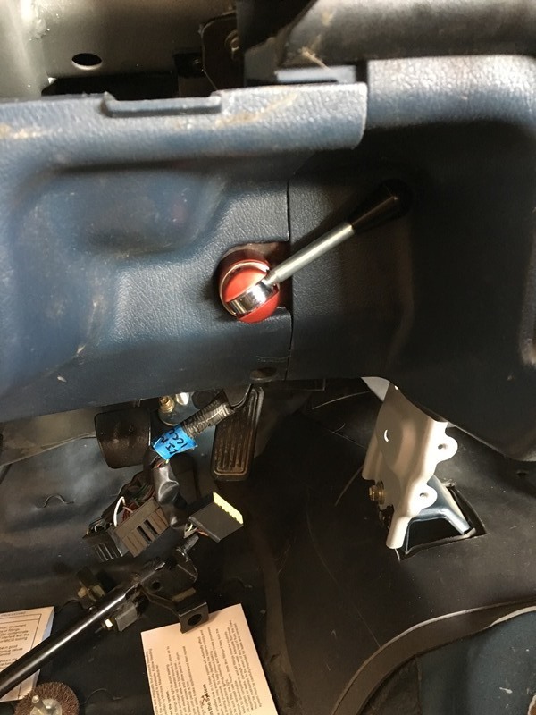
Mocked up in unlocked position
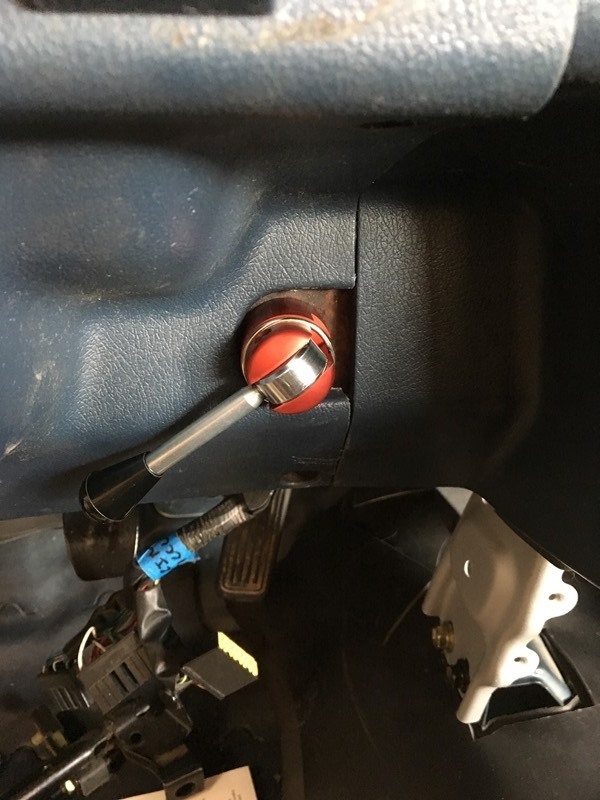
Mocked in locked position
This is how I will have it orientated for now. I may take the knob off and get it machined down so it can be straight up and down. Contours of the interior trim panel won�t allow this to happen. I also wanted flexible hose in the event I needed to move the lock out of the mount or even rotate it without dealing with the hard lines. Again used the old parking brake mount locations for the new bracket.
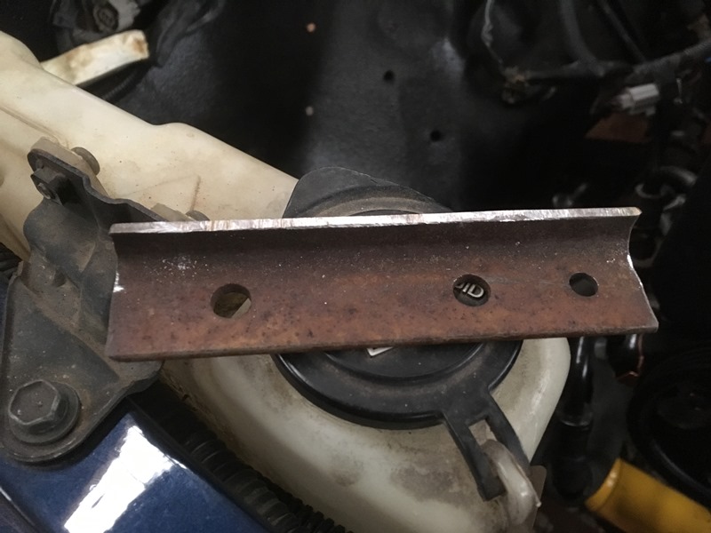
Some just bolt the air box into the old battery tray but I removed mine because it was rusted to hell. I decided to make a bracket to elevate it off the wheel well a little bit. Took 1� angle iron and grinded it down to this
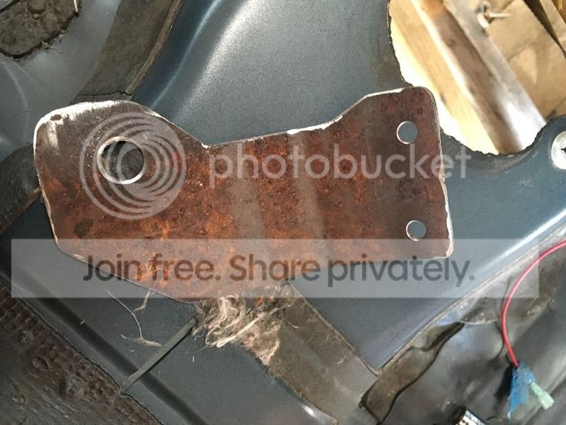
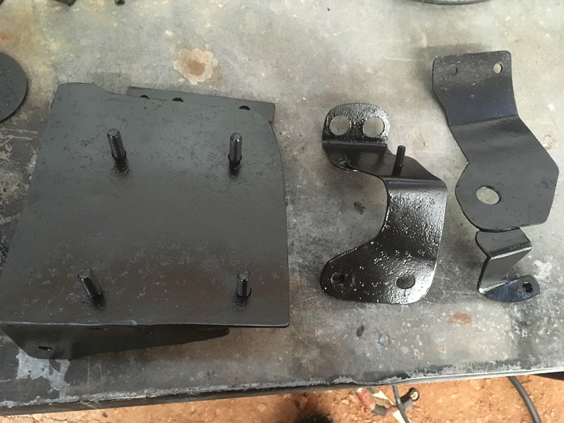
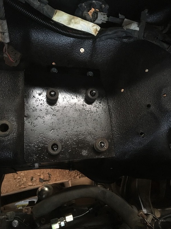
The results of all 3 of the brackets are below. My initial planning of Mico bracket worked but the lock is heavy and with only 2 mounting points I was worried about the stress on the thin piece of steel it mounts to. I added another mounting point. Look below to see where it connects to
I did away with the �whale tail� idea on the air box because I didn�t like the look. 4 bolts welded to the plate will secure it Here is the Mico lock mounted up. The lock comes with a bag of fittings but none are metric. I went to NAPA and they knew a guy that made custom SS flex lines. Had him make one end 10mm and the other 3/8�. Worked great. Admittedly I didn�t try putting the trim on yet so the lower mounting point may need to be modified/redone once I begin putting things together which would be nothing new for me during this swap
Airbox mount and rubber insulators around the bolts in place. Airbox only had 3 of these rubber insulators on the mounts that I broke off so I went to junk yard to get a 4rth. They let me take it for free.
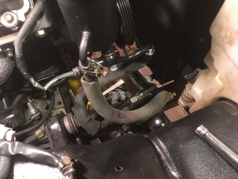
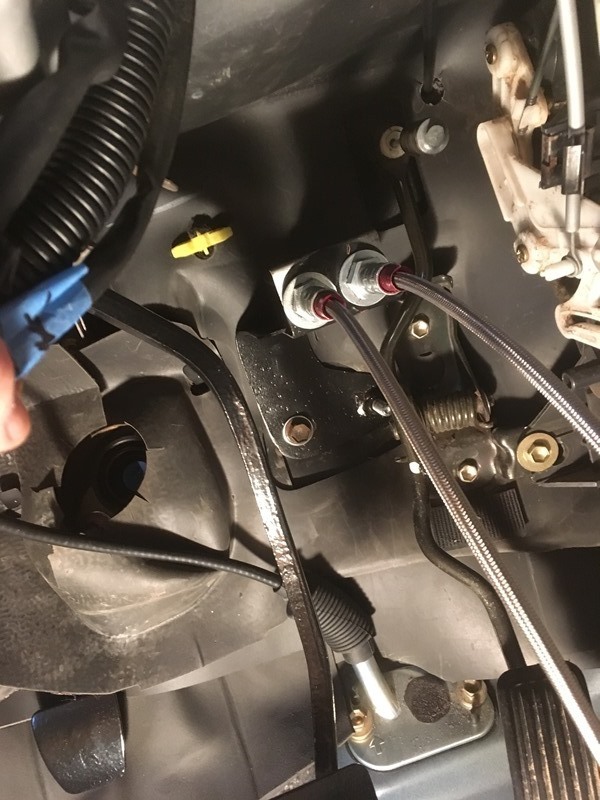
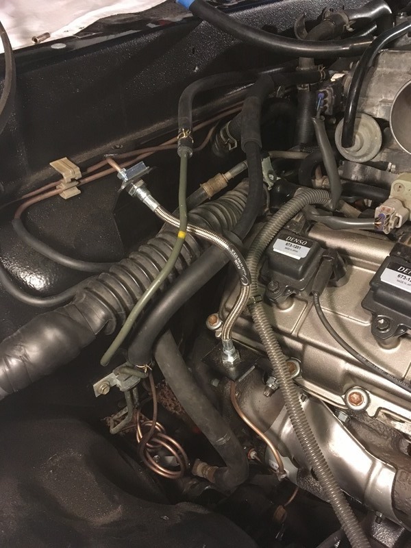
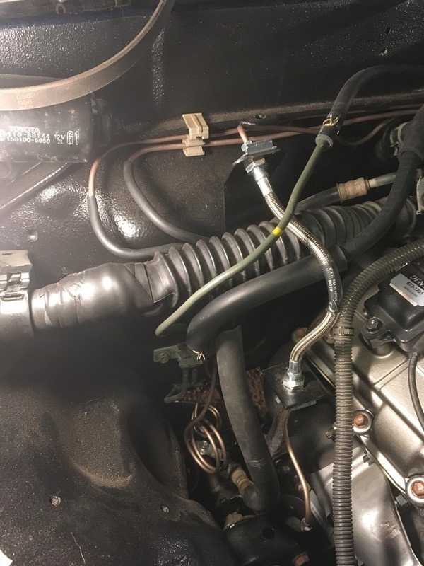
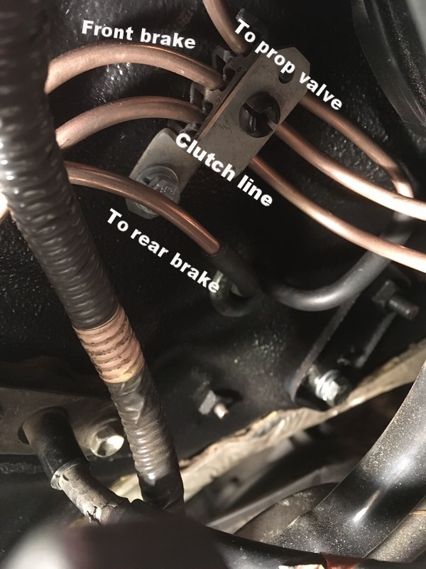
Grab bag of progress� The clutch line going to the fab�d bracket has enough room under for the engine harness. It uses the same factory mounting holes. I made my own line and it does require modification because my fab'd mount is straight vertical which requires the hard line to be shortened a bit. The fuel return line is ran underneath the SS clutch line and the fuel vapor line is ran above the clutch line. The vapor line used to be bolted on the wheel well and went to the charcoal canister. I bent it to this orientation. Below all of this, the brake and 2 fuel lines were mounted on firewall with the factory clips that have rubber insulation in them. Only the fuel line clip can clearly be seen in picture. The high pressure fuel line blocks the brake line clip and this high pressure line needs to be bent with your hands so the hose doesn't rub on the firewall.
Ran the vapor soft line on top of the channel on firewall. Going to use �� line clips to secure it on the wall
One of the clips needs to be egg�d in order for both of them to fit side by side. I took the die grinder to it
I use � drive sockets to make my loops
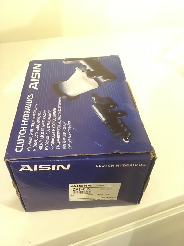
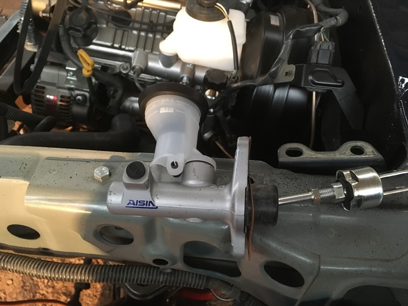
I was going to reuse my old clutch master cylinder but then I thought about the nearly 3 decades of service it�s already put in. Bought an Aisin off of Rockauto
Aisin CMT005
Slide pin in and lock it down. I set the threads the same as the old one.
For fuel return use original hard tube
I blasted and painted it. In operation with new fuel hose. Bolted it on rear of intake where plastic engine harness bolts up with 6mm bolt
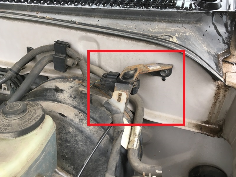
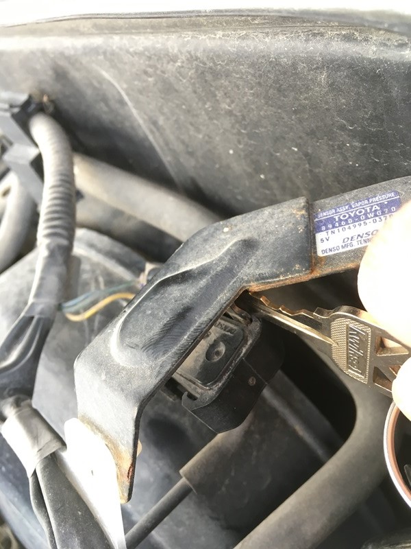
This pressure sensor needs to be moved over from the 3.4
But in my brilliance, I punctured the sensor by removing from the front side of the bracket. Don't do this
New one at Toyota was over $200. So went to pick and pull and got it for $5. The right way to remove the sensor. I didn�t have any tools so used a key
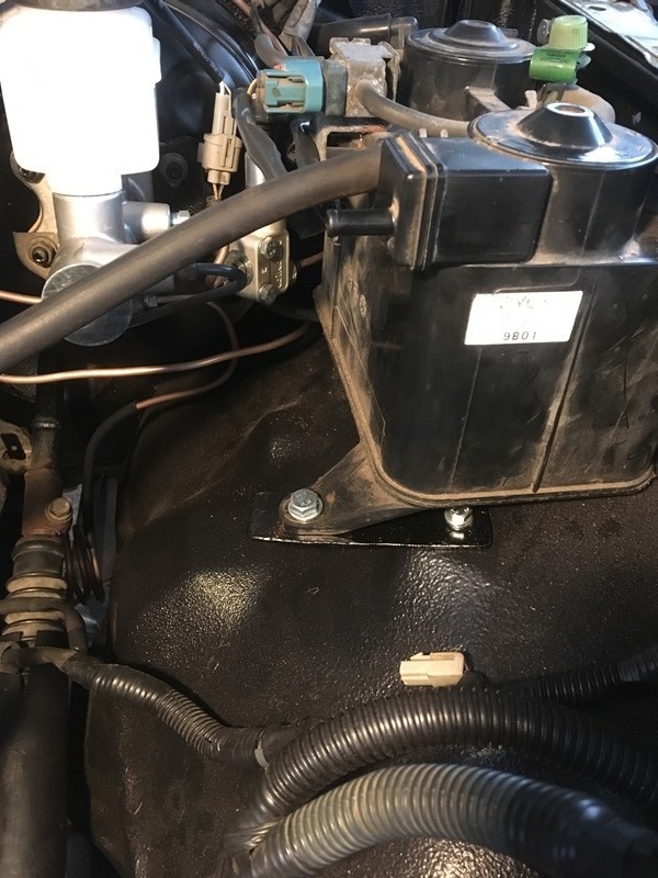
Mounted it on firewall with a 6mm bolt and nut. My cowl is off so I was able to access it. If you do this you will need to take the cowl off in order to fasten it.
From the above picture I used a 3/8� clip to mount the sensor and evap wires on the horizontal ledge that extends out from firewall. This ledge has the brake and clutch hard lines running under it. I used a 6mm bolt and nut in an existing hole.
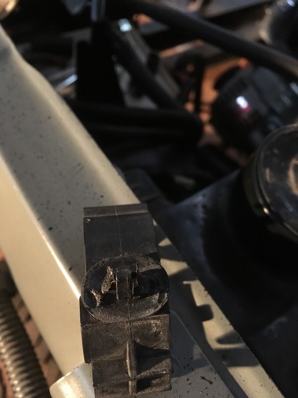
Then I used the plastic clip from the 3.4 that secured sensor/evap wires and a vac line. But in my truck, I used the clip for the vac line and the fuel vapor hose. Clip needs to have the back side shaved because the 3.4 mount hole is much larger. Back side of clip
Bunch of brake line shots along with evaporator box lower mount. Just a piece of flat stock� Also ran the steering shaft through the firewall
Cant say it enough! thank you for all your pics...its has been very helpful for me and my 5vz swap. Again cant wait to see this thing running.
Originally Posted by 84 yota dude
Man attention to detail!
Thanks fellas! Trying to be as detailed as possible but I'm sure I missed some things on the way. Cold as hell outside so things are going to slow down a bit on this end again.
Put some grease on the splines and should slide right in. Be careful with the bushing that the shaft rides on so you don’t blow it out. Didn’t take any pictures of that process as I’m a one man crew and it was a pretty big PITA to do by myself. If you have a friend that could help out I’d recommend it. These are the 3 clips that need to be plugged back into the steering wheel once installed
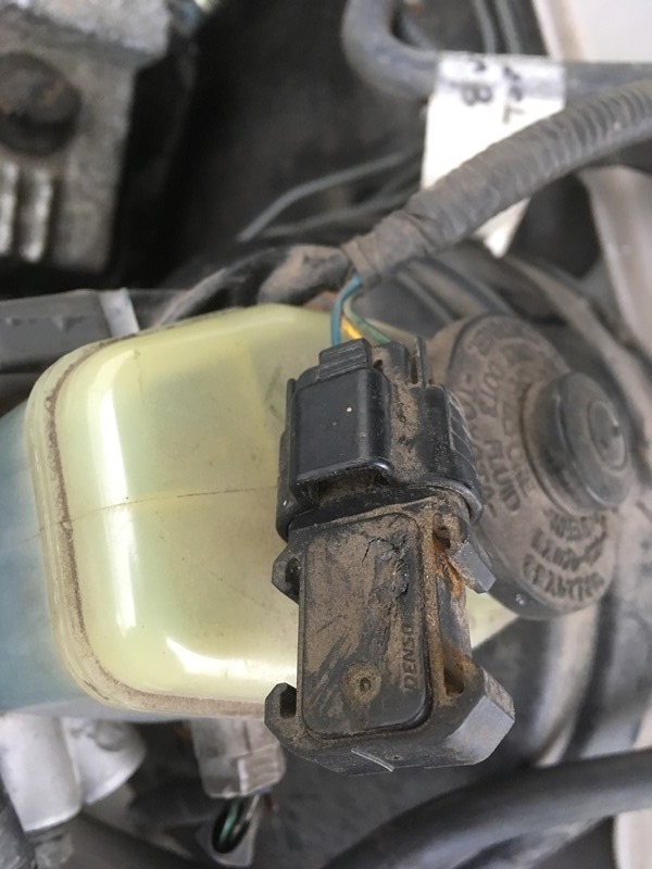
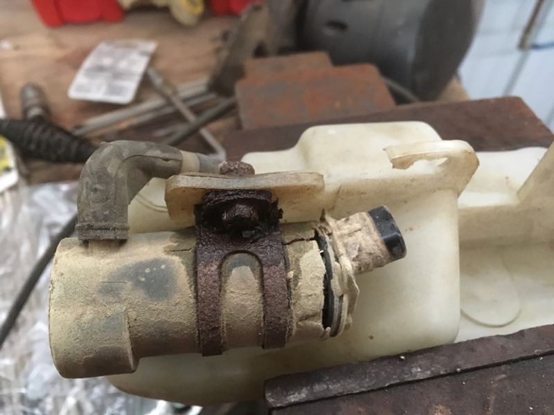
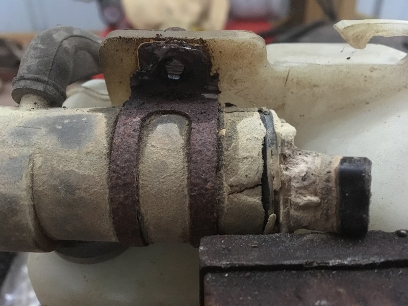
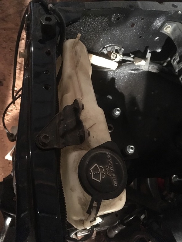
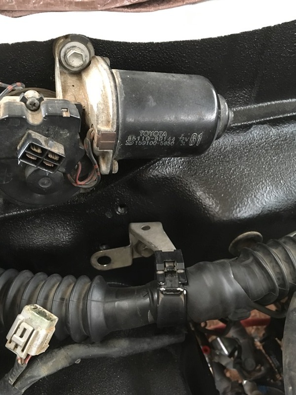
Washer fluid pump and the mount has seen better days. Bolt is rusted on
Took a cutting wheel and carefully cut it off. Took 2 breaks between cutting so I wouldn’t melt the plastic
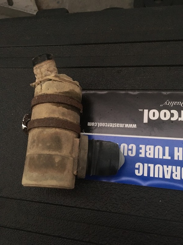
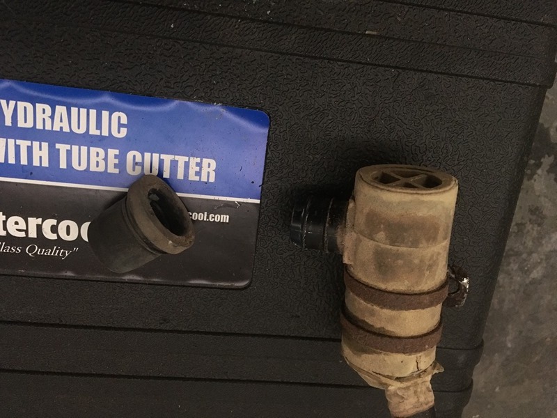
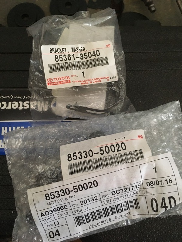
With it off the new pump doesn’t come with the rubber grommet and screen filter. This needs to be removed. Old pump with the goods on it still
Goods removed to be transplanted on new pump
Bracket – 85361-25040
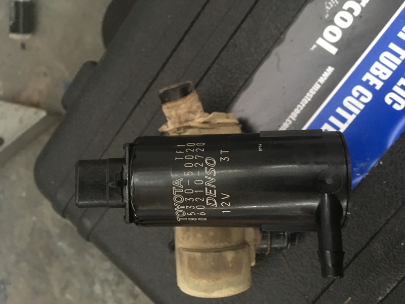
Pump – 85330-50020
New pump
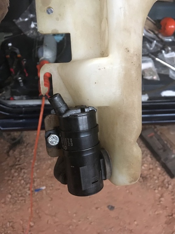
Everything installed. Upgraded the phillips screw with a 6mm hex bolt
And dropped into truck
Last edited by duckhead; Jun 28, 2017 at 06:19 AM.
How do you keep track of where all of the little bits go back to? All of the different little bolts and things I probably am not even aware of when doing this project? I feel like over such a long tear down and build up you can't be doing this by memory!
Did you just take a ton of photo reference or do you have some very detailed Toyota diagrams?
IV been having a hard enough time keeping track of all the different little bolt sizes during my swap, can't imagine your rebuild.
Keep it up, stay warm out there.
Haha, I've often wondered myself! That's probably the biggest question among my friends/family. I'd have to say it's a mixture of memory, pictures, references, and we'll throw luck in there for good measure My obsessive nature with things helps too because it's never fully out of my head and I'm always thinking in pictures.
The bolts sizes are nice because you get a pretty decent feel on a project like this what it's going to be. They're all even metric sizes with generally the same pitch; 6x1, 8x1.25, 10x1.25, 12x1.25 etc. As for the bolts and what goes to what, a good bag and tag system is a must Everything I took apart has a Ziploc bag and the bag is labeled with a sharpy. I also set things up in my barn with the correct orientation as if it was on the truck if that makes sense.
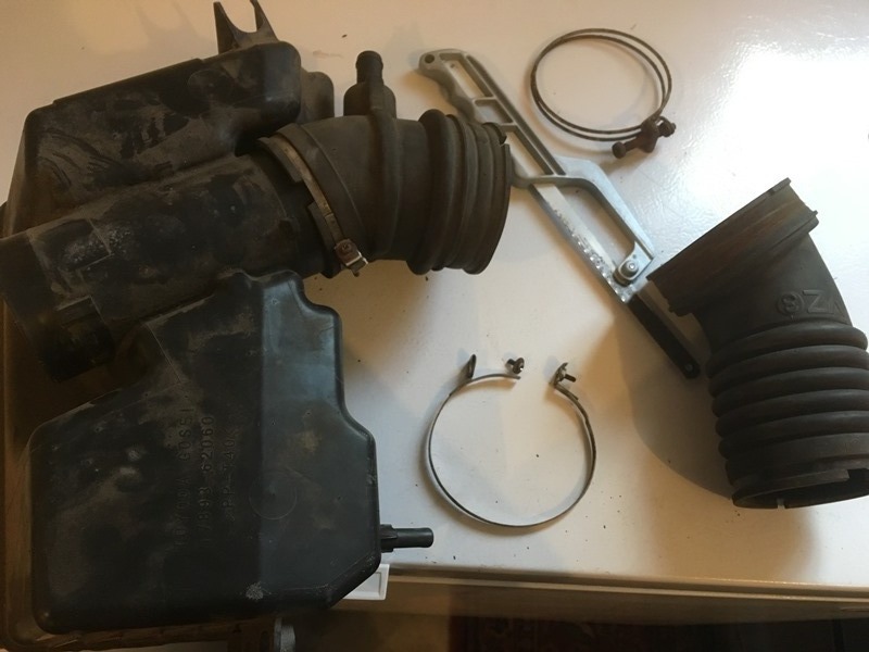
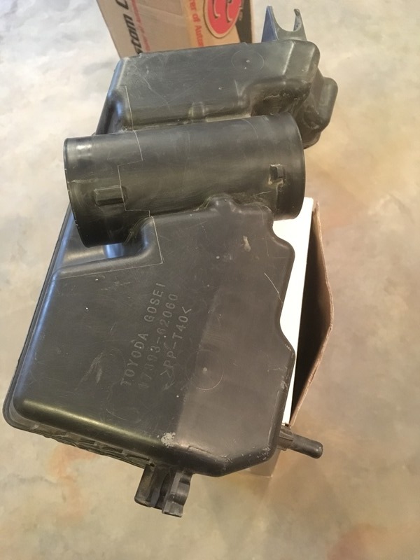
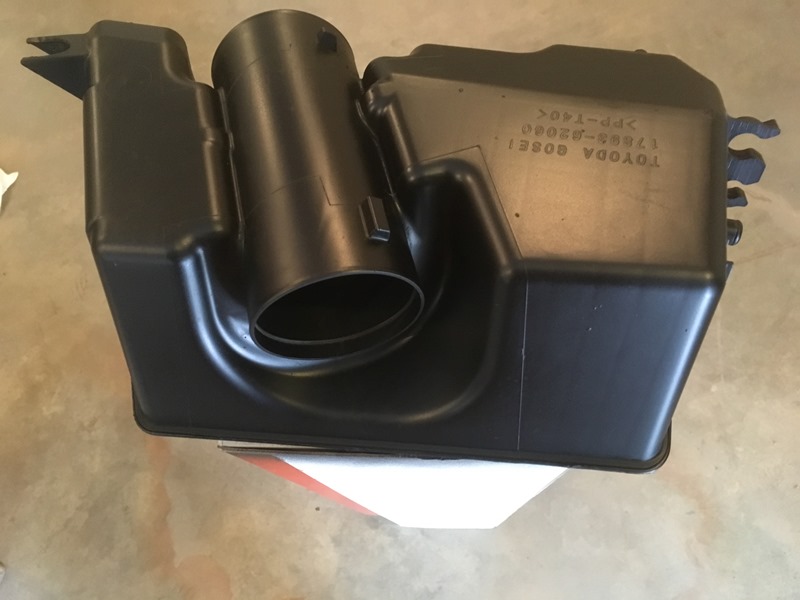
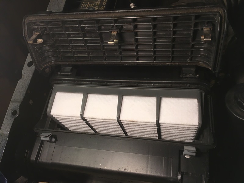
Figured I should rebeautify the air box� Completely disassembled but some of the bands needed to be cut off. Repainted it with Eastwood plastic paint. Stuff worked great.
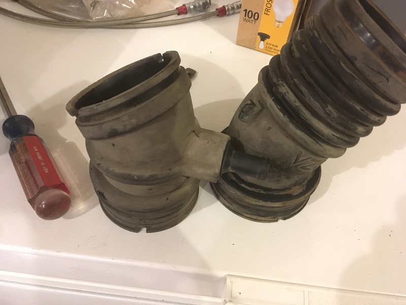
Flex hoses removed
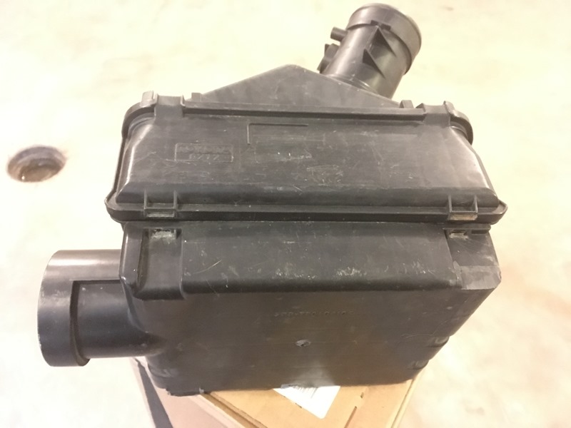
Before
After
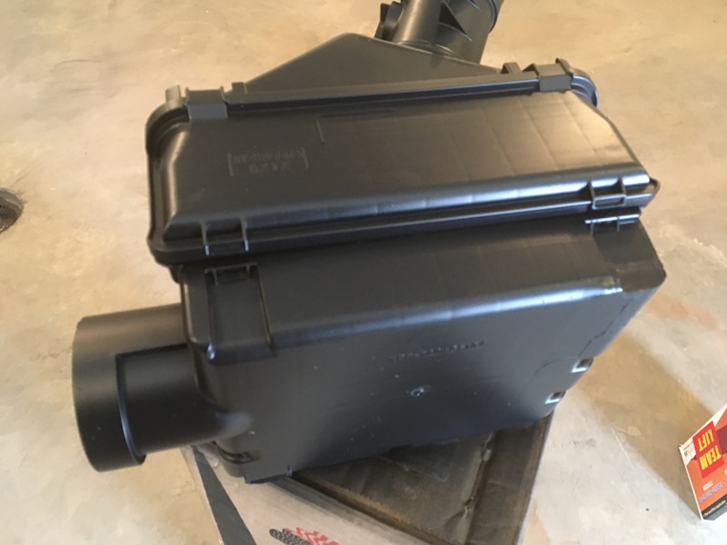
Before
After
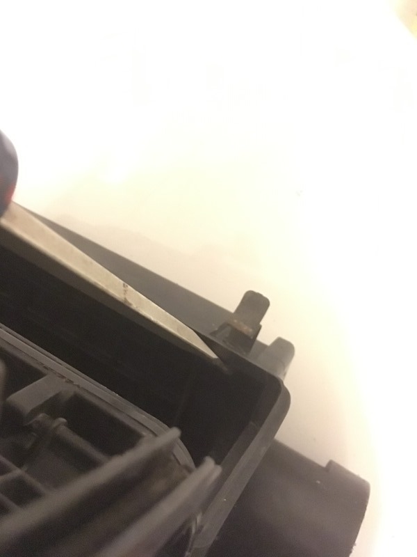
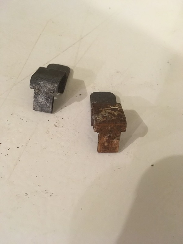
Take a flat head and push out the clips
Pretty rusty clips
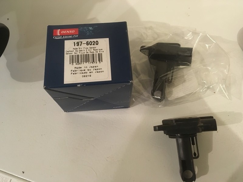
Put in a new Denso MAF from rockauto
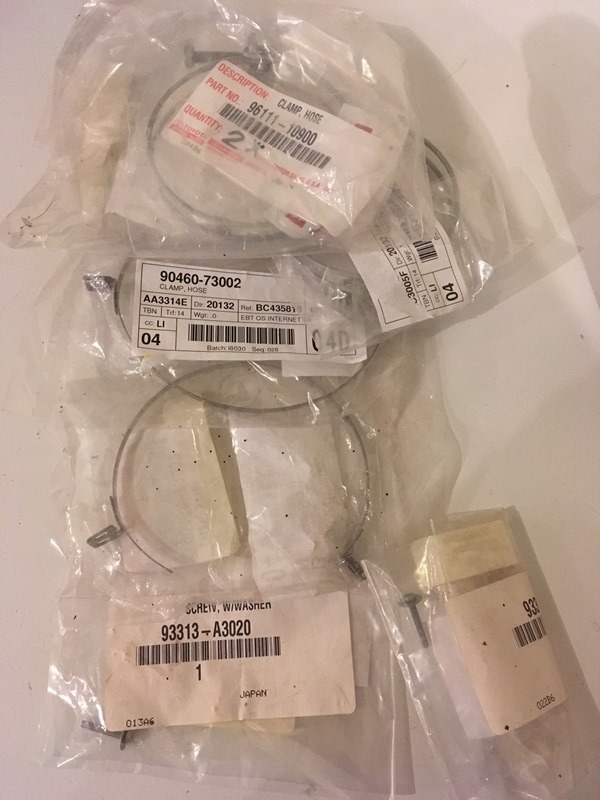
New bands and screws for the tubing
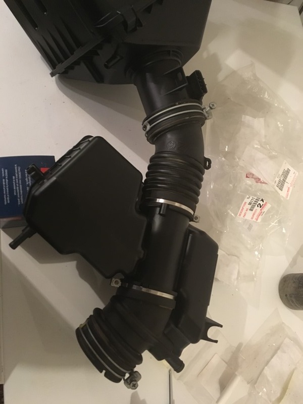
Everything together
Painted the clips and put em in
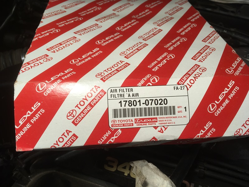
Toyota air filter
Wires clipped in
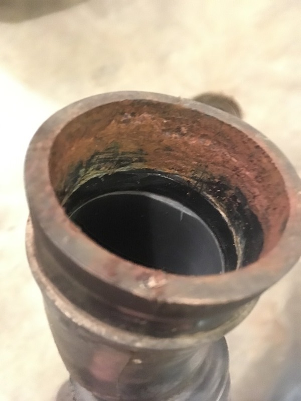
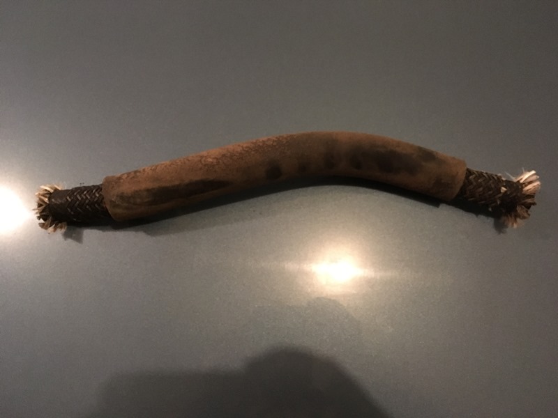
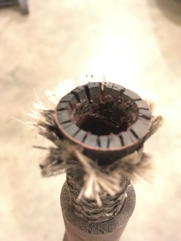
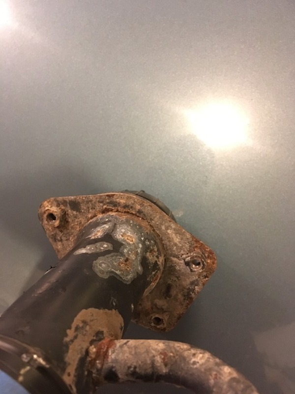
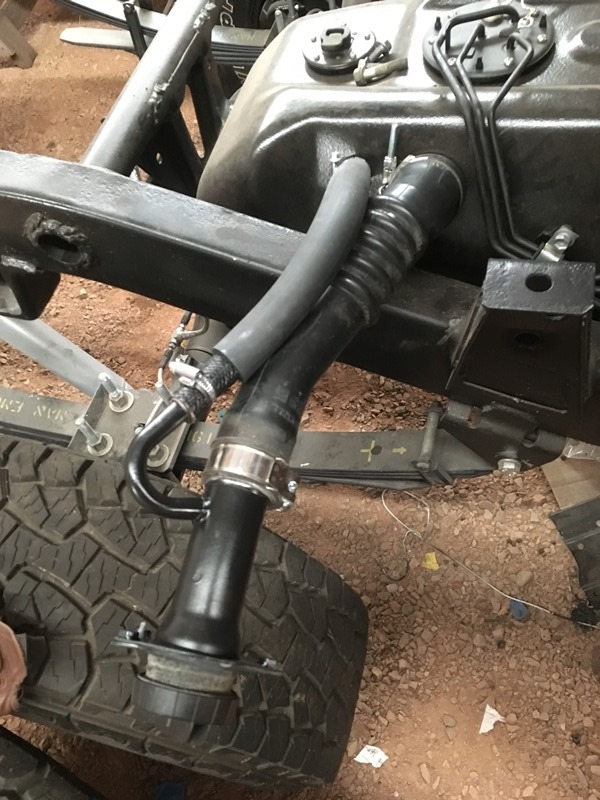
Need to get the gas tank ready for its fill up so I took the tubes off. Some pretty bad rust under em.
The overflow hose is cashed. Will be getting a new one
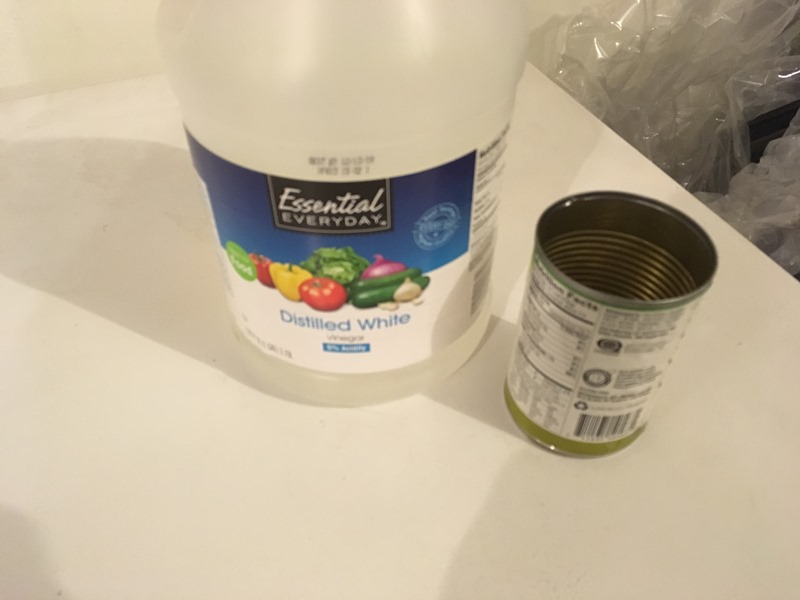
For the filler tube, a little acetic acid (vinegar) did the trick. I didn't want the rust from the hose eating up the new tank. I let it soak for hour or so scraped some off, then soaked, scraped. Turned out good.
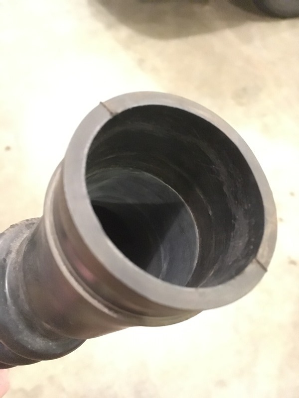
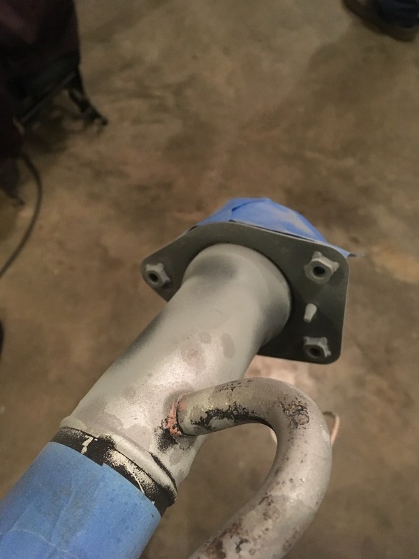
Filler neck pretty rusty so painted it
Wire wheeled and blasted a bit of the filler neck off to get rid of the rust and ready for some paint. Used some zinc rich primer. Half primed and took a pic. Painted black will take pic once dry
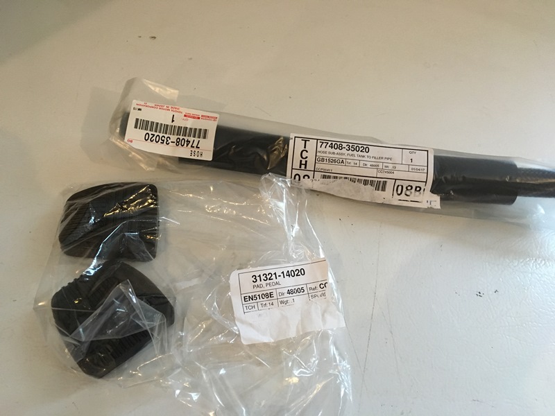
Bought new hose for the bypass and clutch/brake pedal cover.
bypass hose � 77408-35020
brake and clutch pad � 31321-14020
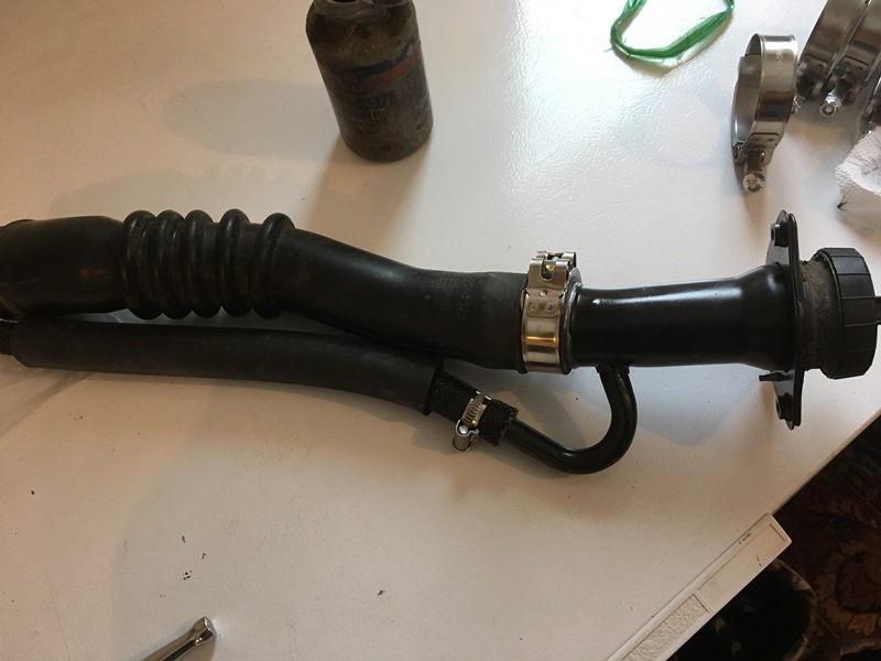
Filler neck turned out good. Put all of that together and got it slapped on the truck. She�s ready for gas!
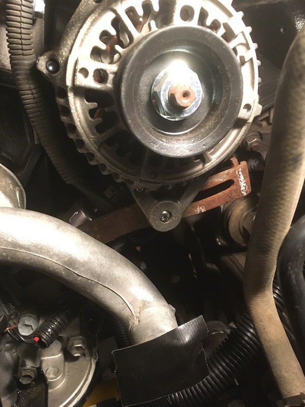
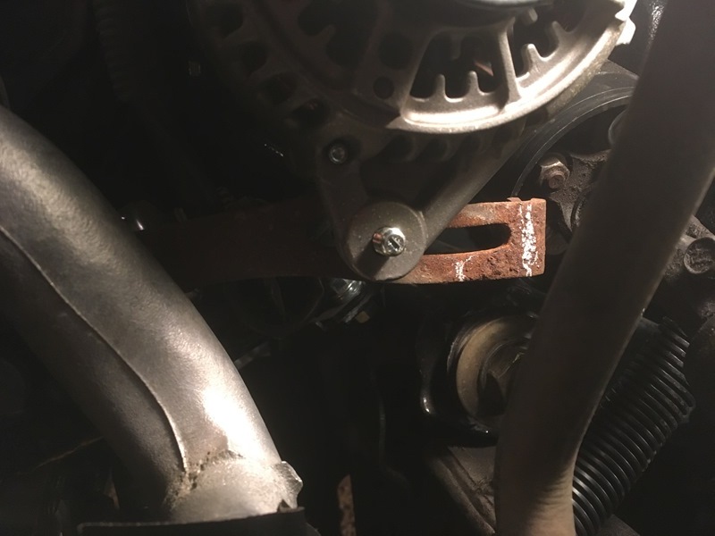
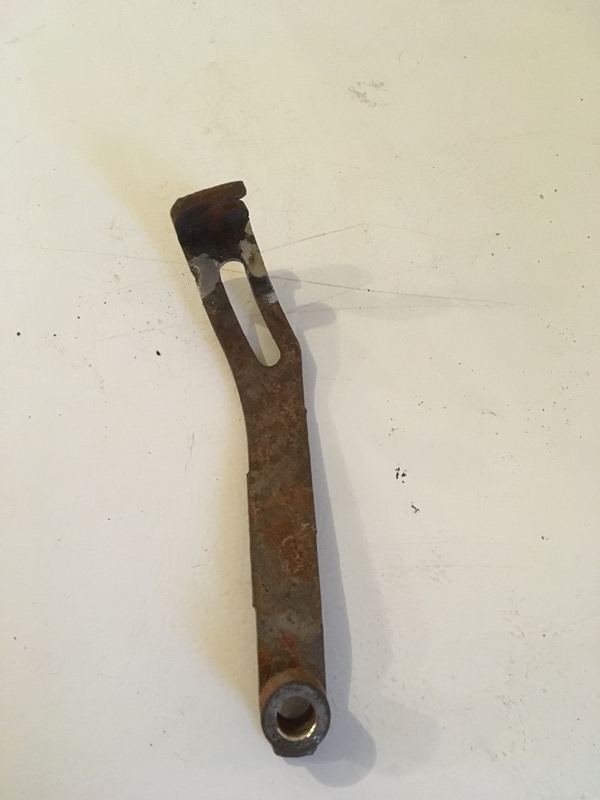
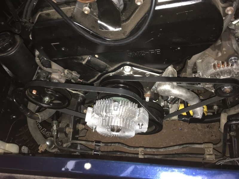
Alternator bracket is always a trouble spot during the swap. I decided to chop mine and weld it back together.
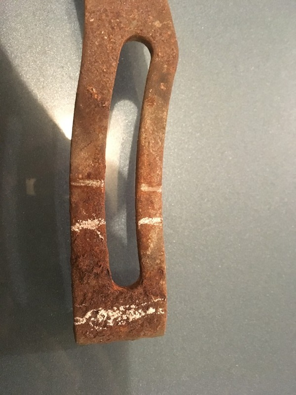
Chalk lines show where chopped. The section inbetween is roughly what I deleted�
This picture shows how close the stock bracket is to the rag joint which is a common complaint during the swap. I could have probably gotten away with it but there wouldn�t be much room for a socket.
Close up of the mock up
I decided to cut a little further than the chalk line. Took a little hand saw to make my final mark
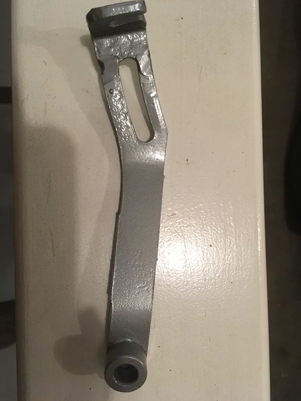
Welded up
Painted
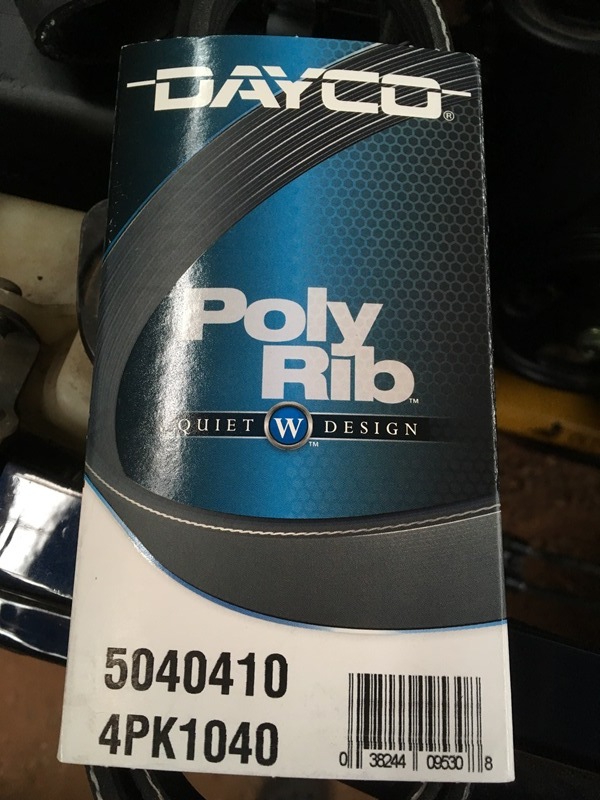
I took most of the bracket off on that once side. It is important to take a die grinder or something to make the other side a little longer. I went with a 41� belt that I bought from Autozone. If you don�t extend that one side I think it would be impossible to get a 41� belt on the truck. I feel like anything longer would be too long. This is the belt from Autozone. Get the part number from the picture.
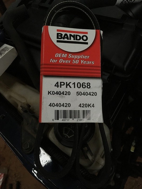
Got a Bando PS pump belt from rockauto for a 2000 4runner.
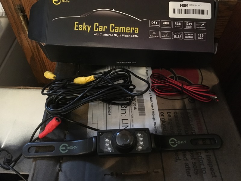
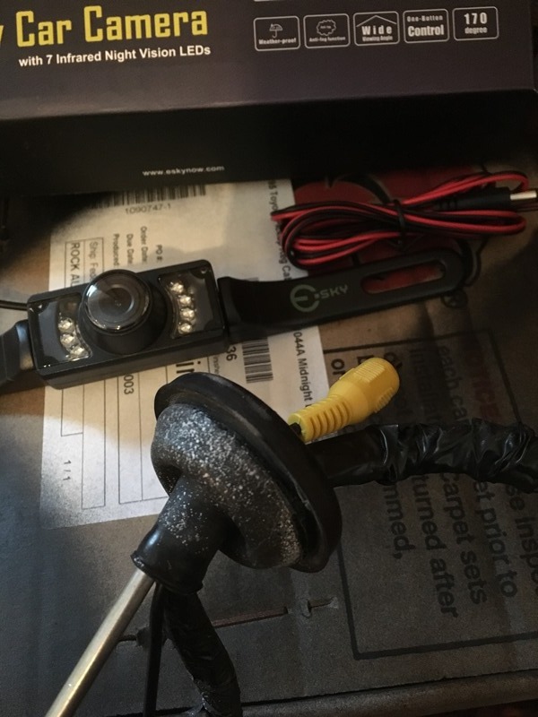
Gonna put a backup camera on the pickup. I went with the Esky from amazon. Cheap and good reviews.
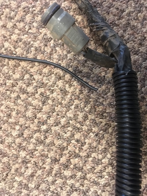
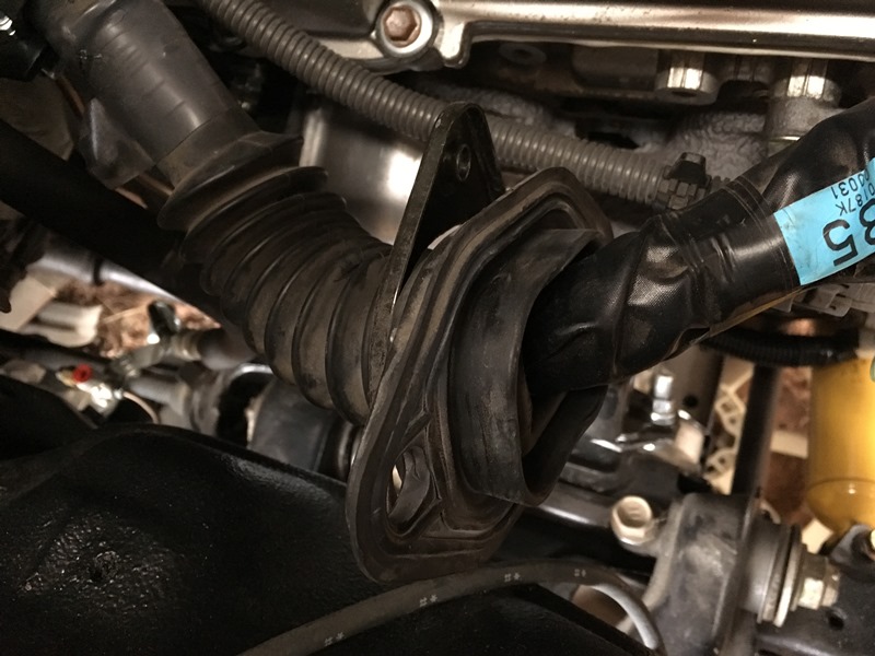
I�m going to run the RCA video cable through the existing rubber grommet that comes out on the passenger side with the rear wire harness. Best to have some extra hands to stretch out the rubber while someone else feeds the RCA plug through the rubber neck.
Everything was going great and then I did something dumb� I was cutting some �� wire loom and snipped through the damn RCA cable. Ah well. Not the first time. Bought a new set off amazon so waiting on those.
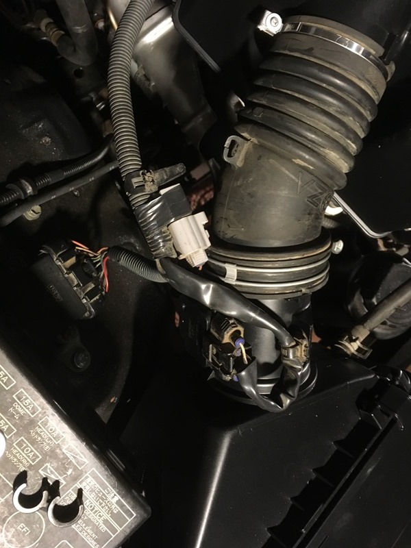
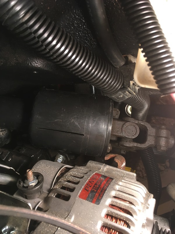
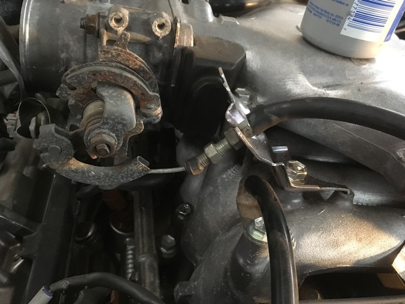
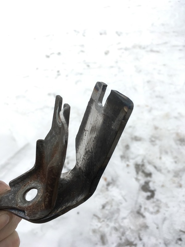
Another semi problem child is the throttle cable bracket. I initially tried the bend method with the factory mount.
The problem with this is there is nearly no adjustability with the throttle cable. The cruise control part of the bracket hits the PCV hose protector. I used a grinder to remove this part of the throttle bracket
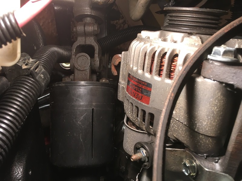
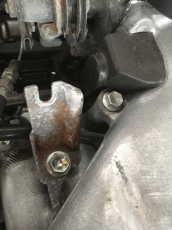
I was going to use this one to cut and splice in a piece of steel to extend it out but I changed my mind. The contours on the factory bracket made it seem like more work than it was worth. I ended up using a thicker piece of flat stock to make my own. This pic shows the extra length needed for a �proper� fitment
Here is the mockup of the cable and bracket
The 3.4 factory throttle cable clip on the driver side of the engine fits perfectly on the 3.0 throttle cable. I cut the booster vacuum hose a bit and it weaves under this cable clip. I bought a new clip and they wrapped the sticker on it. Will take some thinner to it to remove the adhesive later

 Aug 28, 2016 | 06:08 PM


 Making my own lines so not a big deal, just had to go get the correct nuts. I also needed a larger bore master cylinder so I bought Marlin Crawler's big bore
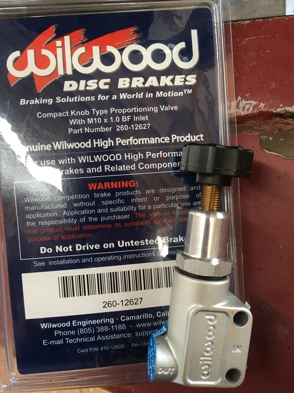


 I can't count how many times I did something only to tear it apart in order to redo it or I saw a better way to do something. I think the bedliner will be worth it from a durability standpoint with falling wrenches or other tools scraping around in there. I'm feeling good about it so far! Diving into my swap pretty hard right now so stay tuned!
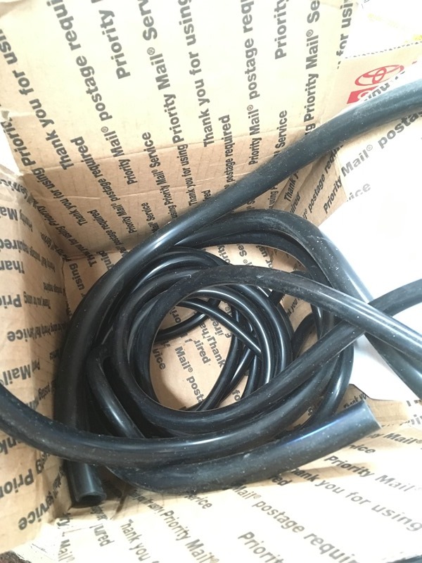


 Soooooo… If anyone wants to go this route, you need this part number;