When you click on links to various merchants on this site and make a purchase, this can result in this site earning a commission. Affiliate programs and affiliations include, but are not limited to, the eBay Partner Network.
Since I haven’t seen, or couldn’t find, something like this here I’m gonna give it a shot and see how it goes. Given my time/schedule this will likely be done in installments. Feel free to ask questions at any time. The terms for parts I’m using here are mine since I could not find a diagram that named the individual parts. If you know of one post it up and I will adjust my terminology.
Since I’ve had a few, annoyingly intermittent, issues around the combo switch on my over 30 year old pickup I figured I should attempt to do something to improve the situation. However, since my truck is driven daily taking it apart to do an autopsy so to speak is a no go. Lucky for me, Hump, one of our fellow Yota guys supplied a suitable donor from an 1986 pickup he plundered – many thanks to Mike .
Based on my research the 1984 through 1988 combo switches are the same as long as the surrounding equipment (tilt wheel vs. not, intermittent wipers vs. not, and SR5) is the same – I am about 90% sure on this. Part number is 84310-35190 for the base model pickup. NOTE: see my UPDATE post below regarding part numbers. A whole new combo switch runs around $200 last I checked – so fixing it may be worth the effort. Admittedly this isn’t the sexiest, or a horsepower producing, part but it is quite useful.
So, first a look at what I am starting with. Here is the whole switch, as you would see it if the steering wheel etc were removed. The hazard switch is on the upper left and the brass pin for the horn is just below and to the right.
Below is a closer look at the mechanism. The white plastic ring around where the steering column goes through is the turn sig cancelling cam – it is able to move up / down along the steering shaft. There are 2 alignment pins protruding out (hard to see in this pic) that go into corresponding holes on the back of the steering wheel. The white plastic piece to the right of the column hole is part of the turn sig actuating arm and moves to the neutral position when the cancelling cam pushes the white plastic piece.
Also note the Phillips head screws, an important item because the various parts attached (headlight turn sig stalk and wires / wiper washer stalk and wires) can be removed from the base of the unit and replaced separately if needed.
Below is a closer shot and from the passenger side of the cancelling cam, with the lobe of the cam marked in red (there are 2 BTW). The round cam part, which turns with the steering wheel, attached via the pins, rubs against the white plastic piece to return the turn sig to the neutral position.
Also note that we have our first issue with this part. Between the 2 Phillips screw heads at the bottom of the picture there is a piece of the base unit broken off. I don’t know if this has a function but I believe it might because there is residual grease at the base of it suggesting there is friction happening there. However, I believe this is where the modular-ness (it’s a word now) can come into play and help. If the base of the combo switch currently on my truck is good I can still use that should I need to change out any of the modules. We shall see later once the rest of this is taken apart and tested.
OK, last bit for now. For those of you who love looking at backsides, this is the backside of the combo switch. On the upper right is the hazard switch and to the left of the column hole is the horn wire (light brown). On the bottom is a factory zip tie that holds the wiring from the modules together and to the base of the unit. You can also see 4 holes, 1 at each corner, where the screws that mount the combo switch go through to attach it to the steering column assembly.
Again note the Phillips head screws that hold the modules to the base. The ones in this pic hold the wiring (in what appear to be little covers) to the base. There will be more on that when I take the modules apart.
P.S. If you see any errors in what I’ve posted so far let me know so I can correct them.
Last edited by L5wolvesf; Jun 4, 2018 at 10:25 AM.
After finding the plastic bits are so very brittle causing much attempted use of Super Glue only to glue fingers together
I also have the worst luck with little parts flying or falling away to never be seen again
So after destroying 3 I gave up
For me buying a New one about ten years ago was a much better option
The only thing I have had good luck fixing was the turn signal cancel operation
You want more parts to play with ?? I think I have two Complete ones in that year range.
Hi Wyo, thanks. Yeah the age of the plastic may be an issue, I�ll find out as I work on them and I�ll try to keep my fingers only attached to ME.
If you have one or 2 you want to send it should be helpful to this article and possibly to my truck. I�ll PM my address to you and let me know how much you want for it. Many thanks.
Also, see my update post below regarding the part numbers.
UPDATE to my first post. As I started to separate the modules I found the part number on the combo switch I’m working on – it is on the connector. The original part number I posted – 84310-35190 – is correct for some years (1984 – 1987) but not others. The part number on the part I’m working on – 84310-35180 – is correct for the same years (1984 – 1987) plus up to 1989. That info came via the links below.
The part number tag, on the connector, on my truck’s switch is gone. It doesn’t matter at this point as I’m going to keep working on what I’ve got.
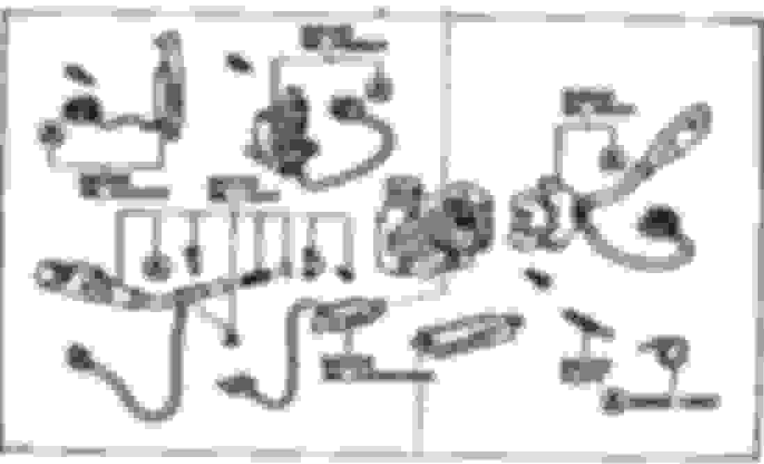
I also found a diagram of the combo switch which I have posted below.
Awesome post! Thank you, Sir! Yeah flying parts are a pain (even with a brand-new ignition switch I got from Beck-Arnley that popped apart as I was installing it).
At least the pitted contacts can be built-up with solder, and that will work - as long as circuit is rewired (or retrofitted with H4 conversion harness) so combo switch will only control the relay, not carry load current.
It will be interesting to see what the inside / contacts look like after 30-plus years of use. There will be pictures and hopefully no smells to describe.
Re the relay wiring � do you have a link to that? I think it would be appropriate here � it would take some load off of some already old electrical parts.
... Re the relay wiring – do you have a link to that? I think it would be appropriate here – it would take some load off of some already old electrical parts.
I simply rewired mine, using ONLY ONE relay to take the place of the low-beam and high-beam contacts of the combo-switch. here. It retains switched-ground configuration and works plug-and-play with my Truck-Lites.
4Crawler has a schematic for making an H4 conversion harness.
I simply rewired mine, using ONLY ONE relay to take the place of the low-beam and high-beam contacts of the combo-switch. here. It retains switched-ground configuration and works plug-and-play with my Truck-Lites.
4Crawler has a schematic for making an H4 conversion harness.
Haven't checked current draw of the wipers, yet.
Hey RAD, thanks for the link, I'll probably do the relay and . . . ask you too many questions.
Did you take pics of your relay set up? 1000 words et al.
And I�m back for PART 2 of this project � disassembly of the Combo Switch. Most of it is fairly easy as the modules are held on with Phillips head screws that attach to the base of the switch � they come off easily.
The difficult part may be taking the base apart into its individual parts. The turn signal (t/s) arm is attached to a pivot which snaps on through a hole in the base. It is the smaller round thing to the right of the steering column hole. As part of removing the modules I removed the t/s arm from the plastic pivoting piece. A WARNING here � the t/s arm has a very small detent ball at its end it could easily fall out and roll away � guess how I found out. It is there for a reason so put it in a container for small parts
I cleaned off the residual grease from the pivot so I could work without the tools and parts slipping around and to keep things relatively clean. The pivot just snaps into the base and I lucked out and found a piece of PVC tubing that fit over the ends of the pivot. It contracted the pivot enough so I could then � gently � pry the pivot piece away from the base without damage. But it takes more than that to separate the pivot piece from the base. There is a lip / track that holds and guides the t/s stalk end of the pivot piece and I do not want to break it. So at this point I will not separate them.
Also, you may recall, in the first part of this project I found there is a piece of the base broken off. I took a quick look at the combo switch in my truck. It looks like the only function of that piece is as a stop. As a stop it is also redundant because on the other side of the pivoting piece (the lip I mentioned above) there is another piece that also acts as a stop. So the base I�m working with here seems to be functional.
What you are seeing are the modules separated from the base. From the right are the; wiper / washer arm with a white cover over the contacts module with the horn wire close by, then the t/s contacts module with a clear cover over the contacts, then the hazard light contacts module, then the t/s arm on the left.
The next step will be to open the covers over where the wires are soldered to the contacts and determine their condition.
I took some additional close up pics before I open the modules.
Turn sig module. Note that there is a spring loaded pin which looks like it fits into the pivot hole on the combo switch base. I’ll look at what it does once the module is opened up. You can see 2 tabs on the right that hold the clear plastic cover on. What you don’t see in the pic is that on the other side 1 of the tabs is broken off – 30 year old plastic is going to be brittle.
Wiper / washer module. The white plastic cover comes off to expose the wiring connections. The green / red wire on the left is the horn wire and the round connector goes over the horn pin.
Hazard lights module. It looks pretty simple but it does come apart.

 Jun 3, 2018 | 01:23 PM

 .
.