
Alternator wiring/fusing 22RE
 Nov 20, 2019 | 02:14 PM
#1

Thread Starter
Registered User
Joined: Sep 2008
Posts: 95
Likes: 37
Alternator wiring/fusing 22RE
I started playing around with the wiring on my 1980 pickup, with 1990 22RE swap.
I started this little project because my truck idles rough with the headlight or heater fan on. Pretty much anything that draws power causes rough idle.
In an attempt to reduce resistance in the wiring, I replaced all my battery cables and grounds. I used #2 welding cable, tinned copper ring terminals and marine shrink tube. This didn't help.
I think my charging system could be wired better and I need to get things properly fused. I picked up some #6 welding cable and am now trying to figure out how to wire this thing.
When the EFI swap was done all power wires went to the battery, no fuses. I added a gutted 2nd gen fuse box, using only the 30A,40A and 80A fusible link cartridges. This is how things are currently wired.
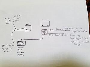

I am reading that the ALT. "SENSE" wire should be run to a junction close to the battery.
I am thinking the CHARGE wire should be kept in the engine bay, rather than run through the cab, as it is now.
I am also thinking the in cab fuse box wire should be run to a junction, rather than tapped into the CHARGE wire.
I am not confident In what I am doing and I'm having trouble figuring out how to properly fuse everything. The 2nd gen fuse box doesn't hold enough fusible link cartridges.
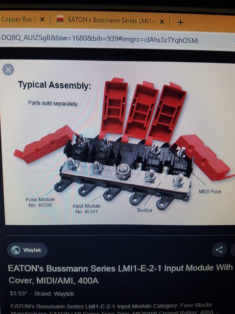
I was going to run everything to a buss bar and use fusible link wire, like this. I am told that all Toyota fusible links are 4 1/2" long and they need to be 4 sizes smaller than the wire they are protecting.
Now, I have discovered AMI/MIDI fuses. I'm thinking this is the way to go, using a AMI/MIDI buss bar. They are a 'slow blow" fuse, so I'm thinking they are a safe alternative to the fusible link cartridges. I would love to hear some thoughts on this. Does my wiring plan look good?


If you have read this far, thank you.
I started this little project because my truck idles rough with the headlight or heater fan on. Pretty much anything that draws power causes rough idle.
In an attempt to reduce resistance in the wiring, I replaced all my battery cables and grounds. I used #2 welding cable, tinned copper ring terminals and marine shrink tube. This didn't help.
I think my charging system could be wired better and I need to get things properly fused. I picked up some #6 welding cable and am now trying to figure out how to wire this thing.
When the EFI swap was done all power wires went to the battery, no fuses. I added a gutted 2nd gen fuse box, using only the 30A,40A and 80A fusible link cartridges. This is how things are currently wired.

I am reading that the ALT. "SENSE" wire should be run to a junction close to the battery.
I am thinking the CHARGE wire should be kept in the engine bay, rather than run through the cab, as it is now.
I am also thinking the in cab fuse box wire should be run to a junction, rather than tapped into the CHARGE wire.
I am not confident In what I am doing and I'm having trouble figuring out how to properly fuse everything. The 2nd gen fuse box doesn't hold enough fusible link cartridges.
I was going to run everything to a buss bar and use fusible link wire, like this. I am told that all Toyota fusible links are 4 1/2" long and they need to be 4 sizes smaller than the wire they are protecting.

Now, I have discovered AMI/MIDI fuses. I'm thinking this is the way to go, using a AMI/MIDI buss bar. They are a 'slow blow" fuse, so I'm thinking they are a safe alternative to the fusible link cartridges. I would love to hear some thoughts on this. Does my wiring plan look good?

If you have read this far, thank you.
Last edited by toyoda addict; Nov 27, 2019 at 11:04 AM.
Nov 27, 2019 | 08:16 AM
#2

Registered User
Joined: Jan 2016
Posts: 221
Likes: 37
From: Where Prairie meets Mountians
Well your pictures are a bit small and/or I am too lazy to enlarge them but from what I see it looks O/K. I don't know what to do about the S wire, and not even going to guess. I did almost the same thing with my 83 but used type 1 circuit breakers. I also added a master fuse (ANS80) for the entire electrical system (except the starter) and a continuous duty solenoid (to turn that power off from a keyed and pushbutton switch in the cab) between the battery and the loads. I also added a fuse to the white output wire of the alternator (ANS50). I also measured how much current each fused load drew and re-fused appropriately and have had no nuisance fuse blows. In some cases I found the fusing was as much as 300% more then required. For example, as best I can remember, the wiper motor drew around 8 amps stalled and I believe the original fuse was 15 or 20 amps and one day it did stall and snapped all the nylon bushings in the wiper transmission linkage. The fuse is likely a 7.5 amp now.
I don't have all the new fuse values handy right now but can get them in the next day or two of you're interested.
I did this because of an acquaintance of mine had an 1986 Toyota 2 wheel drive PU made into street racer. The guy had turbo, nitrous, chopped and lowered, pearl green paint job...the whole ball of wax. Likely had 25-30K into not counting the truck and its restoration...had a electrical short and the truck burnt to the ground in his driveway a complete loss!
Last edited by Old83@pincher; Nov 27, 2019 at 08:20 AM.
Nov 27, 2019 | 10:53 AM
#3
Thread Starter
Registered User
Joined: Sep 2008
Posts: 95
Likes: 37
Well your pictures are a bit small and/or I am too lazy to enlarge them but from what I see it looks O/K. I don't know what to do about the S wire, and not even going to guess. I did almost the same thing with my 83 but used type 1 circuit breakers. I also added a master fuse (ANS80) for the entire electrical system (except the starter) and a continuous duty solenoid (to turn that power off from a keyed and pushbutton switch in the cab) between the battery and the loads. I also added a fuse to the white output wire of the alternator (ANS50). I also measured how much current each fused load drew and re-fused appropriately and have had no nuisance fuse blows. In some cases I found the fusing was as much as 300% more then required. For example, as best I can remember, the wiper motor drew around 8 amps stalled and I believe the original fuse was 15 or 20 amps and one day it did stall and snapped all the nylon bushings in the wiper transmission linkage. The fuse is likely a 7.5 amp now.
I don't have all the new fuse values handy right now but can get them in the next day or two of you're interested.
I did this because of an acquaintance of mine had an 1986 Toyota 2 wheel drive PU made into street racer. The guy had turbo, nitrous, chopped and lowered, pearl green paint job...the whole ball of wax. Likely had 25-30K into not counting the truck and its restoration...had a electrical short and the truck burnt to the ground in his driveway a complete loss!
I don't have all the new fuse values handy right now but can get them in the next day or two of you're interested.
I did this because of an acquaintance of mine had an 1986 Toyota 2 wheel drive PU made into street racer. The guy had turbo, nitrous, chopped and lowered, pearl green paint job...the whole ball of wax. Likely had 25-30K into not counting the truck and its restoration...had a electrical short and the truck burnt to the ground in his driveway a complete loss!
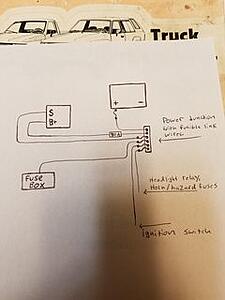
I havent been able to get much input on any of this, so I went ahead and ordered the AMI/midi fuses. This is the plan as of now. Hopefully I have the wiring right.
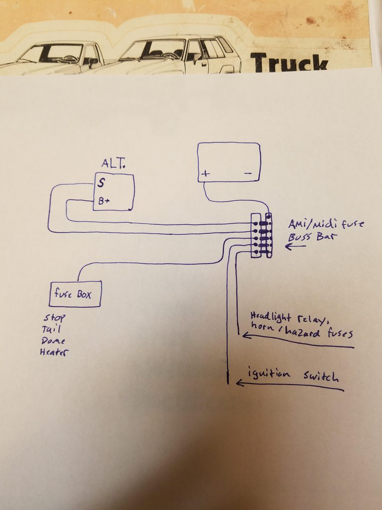
B+ 80A
S 40A
Ignition. 40A
fuse box. 60A
Headlight relay/horn/hazard fuse 30A
Last edited by toyoda addict; Nov 27, 2019 at 10:56 AM.
Nov 27, 2019 | 03:59 PM
#4
Registered User
Joined: Jan 2016
Posts: 221
Likes: 37
From: Where Prairie meets Mountians
O/K I will get the fuse sizes but it could take a day or two. Usually my notes are only understandable by myself and currently they are about 150 kilometers from me. I may even have a schematic of the new wiring that someone other then myself can understand.
I used my clamp on AC/DC ammeter that I got for work for the measurements. You don't have to open the circuit and put it in series, just clamp it around the conductor. Some of the currents are just beyond the range of a basic multi-meter. I think I paid about $350 for it 20 years ago, but I believe the prices have come down considerably since.
You probably don't need a 60amp fuse for the 'fuse box' as those mentioned loads really only add up to about 20-25amps if they are all on at the same time. You can split it off the 'charge' wire if you wish. This would have the added benefit of being able to install an ammeter if you wish. All loads would have to be on the alternator side. (In your diagram #2, between the battery and the new fuse block)
I recommend since you're kind of green at wiring to get some books for your library (old school, which is usually the best school) or from the ingornet and study some basic automotive wiring/electrical systems.
Last edited by Old83@pincher; Nov 27, 2019 at 04:18 PM.
Nov 27, 2019 | 05:14 PM
#5
Thread Starter
Registered User
Joined: Sep 2008
Posts: 95
Likes: 37
O/K I will get the fuse sizes but it could take a day or two. Usually my notes are only understandable by myself and currently they are about 150 kilometers from me. I may even have a schematic of the new wiring that someone other then myself can understand.
I used my clamp on AC/DC ammeter that I got for work for the measurements. You don't have to open the circuit and put it in series, just clamp it around the conductor. Some of the currents are just beyond the range of a basic multi-meter. I think I paid about $350 for it 20 years ago, but I believe the prices have come down considerably since.
You probably don't need a 60amp fuse for the 'fuse box' as those mentioned loads really only add up to about 20-25amps if they are all on at the same time. You can split it off the 'charge' wire if you wish. This would have the added benefit of being able to install an ammeter if you wish. All loads would have to be on the alternator side. (In your diagram #2, between the battery and the new fuse block)
I recommend since you're kind of green at wiring to get some books for your library (old school, which is usually the best school) or from the ingornet and study some basic automotive wiring/electrical systems.
I used my clamp on AC/DC ammeter that I got for work for the measurements. You don't have to open the circuit and put it in series, just clamp it around the conductor. Some of the currents are just beyond the range of a basic multi-meter. I think I paid about $350 for it 20 years ago, but I believe the prices have come down considerably since.
You probably don't need a 60amp fuse for the 'fuse box' as those mentioned loads really only add up to about 20-25amps if they are all on at the same time. You can split it off the 'charge' wire if you wish. This would have the added benefit of being able to install an ammeter if you wish. All loads would have to be on the alternator side. (In your diagram #2, between the battery and the new fuse block)
I recommend since you're kind of green at wiring to get some books for your library (old school, which is usually the best school) or from the ingornet and study some basic automotive wiring/electrical systems.
I don't understand what you mean by this "All loads would have to be on the alternator side. (In your diagram #2, between the battery and the new fuse block)" I don't plan to run an ammeter. I was hoping to not have to tap the in cab fuse box wire into the new charge wire (mainly for convenience).
I agree about getting some books. I am always trying to learn. I was going to order Electric Wiring Tech made Simple from Mad Electrical, if they're still in business.
Nov 28, 2019 | 03:40 PM
#6
Registered User
Joined: Jan 2016
Posts: 221
Likes: 37
From: Where Prairie meets Mountians
I'll try a 40A on the in cab fuse box wire. Its AVS 5 so 10 gauge wire. As I understand it 40A or 60A should keep it from burning, correct?
I don't understand what you mean by this "All loads would have to be on the alternator side. (In your diagram #2, between the battery and the new fuse block)" I don't plan to run an ammeter. I was hoping to not have to tap the in cab fuse box wire into the new charge wire .
I don't understand what you mean by this "All loads would have to be on the alternator side. (In your diagram #2, between the battery and the new fuse block)" I don't plan to run an ammeter. I was hoping to not have to tap the in cab fuse box wire into the new charge wire .
If you're not going to have any plans for an ammeter, just forget about what I said about installing one! When you start to read up about this stuff, you will get a better understanding of it then I could possibly try to explain!
Should have those fuse/amperage values for you soon.
Nov 28, 2019 | 04:31 PM
#7
Registered User
Joined: Jan 2016
Posts: 221
Likes: 37
From: Where Prairie meets Mountians
O/K that answer of mine about the ammeter is a bit...well pick a nasty word.
An ammeter is there to monitor the charging or discharging of the battery and if you have enough 'sixth sense' you can estimate the output of the alternator and the amount of current the loads are consuming.
For example, if your alternator is rated 50amps and you have 60amps of loads, the ammeter will read a 10 amp discharge of the battery. If the vehicle is idling it will not be able to put out 50amps, we'll say only 20amps. With the same 60amp load the ammeter will read a battery discharge of 40amps...continue that for about 2 hours and most batteries will be dead. Problems will start before that as the electronics in a modern vehicle are voltage sensitive and will start to operate erratically. Old school vehicles will continue to operate right to the end (carburetor, points and condenser ignition, etc.) O/K on the good side, after you start the vehicle you will see the ammeter read about a 30 to 50 amp charge, after a short period of time the needle will move to about a 10amp charge...this is good as its showing you the alternator has recharged the battery after starting and maintaining a positive charge on the battery. If you start driving away and say put the headlights on then the alternator will put out another 20amps. this means the alternator is putting out now 30 amps...20 to the headlights and 10 to the battery and the ammeter will read 10amps. You can continue to load the alternator up to 40amps with no change to the ammeter. Between 40 and 50amps of load you will see the ammeter go from a 10amp charge to zero as the increased load is taking away charge going to the battery. At this point there will probably be a voltage drop from 14v to 12V. This is O/K and can go on almost indefinitely. Now if you add more load, you will discharge the battery as the battery needs to provide power to loads that the alternator can't. Normally the alternator provides all the power for all the loads. Now us truck guys like to add a billion 100watt off road lights, winches and so on, and that's where the problems start. That's why guys will do alternator upgrades. If you always see a substantial charge this indicates a problem in the charging system, a bad regulator or maybe a shorted cell in the battery.
So...that's why all loads must be connected to the alternator side of the ammeter. You will not have to tap into the fuse box wire as you suggested whether you want an ammeter or not. In fact on a lock stock truck all you need to do to put in an ammeter is take all the fuse links off the battery terminal join them together and run a wire from there to the ammeter and then one back from the ammeter to where those fuse links originally were. It would look messy and definitely not be good wiring practice, but it would work.
Last edited by Old83@pincher; Nov 28, 2019 at 04:45 PM.
Trending Topics
Nov 29, 2019 | 12:44 PM
#8
Thread Starter
Registered User
Joined: Sep 2008
Posts: 95
Likes: 37
O/K that answer of mine about the ammeter is a bit...well pick a nasty word.
An ammeter is there to monitor the charging or discharging of the battery and if you have enough 'sixth sense' you can estimate the output of the alternator and the amount of current the loads are consuming.
For example, if your alternator is rated 50amps and you have 60amps of loads, the ammeter will read a 10 amp discharge of the battery. If the vehicle is idling it will not be able to put out 50amps, we'll say only 20amps. With the same 60amp load the ammeter will read a battery discharge of 40amps...continue that for about 2 hours and most batteries will be dead. Problems will start before that as the electronics in a modern vehicle are voltage sensitive and will start to operate erratically. Old school vehicles will continue to operate right to the end (carburetor, points and condenser ignition, etc.) O/K on the good side, after you start the vehicle you will see the ammeter read about a 30 to 50 amp charge, after a short period of time the needle will move to about a 10amp charge...this is good as its showing you the alternator has recharged the battery after starting and maintaining a positive charge on the battery. If you start driving away and say put the headlights on then the alternator will put out another 20amps. this means the alternator is putting out now 30 amps...20 to the headlights and 10 to the battery and the ammeter will read 10amps. You can continue to load the alternator up to 40amps with no change to the ammeter. Between 40 and 50amps of load you will see the ammeter go from a 10amp charge to zero as the increased load is taking away charge going to the battery. At this point there will probably be a voltage drop from 14v to 12V. This is O/K and can go on almost indefinitely. Now if you add more load, you will discharge the battery as the battery needs to provide power to loads that the alternator can't. Normally the alternator provides all the power for all the loads. Now us truck guys like to add a billion 100watt off road lights, winches and so on, and that's where the problems start. That's why guys will do alternator upgrades. If you always see a substantial charge this indicates a problem in the charging system, a bad regulator or maybe a shorted cell in the battery.
So...that's why all loads must be connected to the alternator side of the ammeter. You will not have to tap into the fuse box wire as you suggested whether you want an ammeter or not. In fact on a lock stock truck all you need to do to put in an ammeter is take all the fuse links off the battery terminal join them together and run a wire from there to the ammeter and then one back from the ammeter to where those fuse links originally were. It would look messy and definitely not be good wiring practice, but it would work.
An ammeter is there to monitor the charging or discharging of the battery and if you have enough 'sixth sense' you can estimate the output of the alternator and the amount of current the loads are consuming.
For example, if your alternator is rated 50amps and you have 60amps of loads, the ammeter will read a 10 amp discharge of the battery. If the vehicle is idling it will not be able to put out 50amps, we'll say only 20amps. With the same 60amp load the ammeter will read a battery discharge of 40amps...continue that for about 2 hours and most batteries will be dead. Problems will start before that as the electronics in a modern vehicle are voltage sensitive and will start to operate erratically. Old school vehicles will continue to operate right to the end (carburetor, points and condenser ignition, etc.) O/K on the good side, after you start the vehicle you will see the ammeter read about a 30 to 50 amp charge, after a short period of time the needle will move to about a 10amp charge...this is good as its showing you the alternator has recharged the battery after starting and maintaining a positive charge on the battery. If you start driving away and say put the headlights on then the alternator will put out another 20amps. this means the alternator is putting out now 30 amps...20 to the headlights and 10 to the battery and the ammeter will read 10amps. You can continue to load the alternator up to 40amps with no change to the ammeter. Between 40 and 50amps of load you will see the ammeter go from a 10amp charge to zero as the increased load is taking away charge going to the battery. At this point there will probably be a voltage drop from 14v to 12V. This is O/K and can go on almost indefinitely. Now if you add more load, you will discharge the battery as the battery needs to provide power to loads that the alternator can't. Normally the alternator provides all the power for all the loads. Now us truck guys like to add a billion 100watt off road lights, winches and so on, and that's where the problems start. That's why guys will do alternator upgrades. If you always see a substantial charge this indicates a problem in the charging system, a bad regulator or maybe a shorted cell in the battery.
So...that's why all loads must be connected to the alternator side of the ammeter. You will not have to tap into the fuse box wire as you suggested whether you want an ammeter or not. In fact on a lock stock truck all you need to do to put in an ammeter is take all the fuse links off the battery terminal join them together and run a wire from there to the ammeter and then one back from the ammeter to where those fuse links originally were. It would look messy and definitely not be good wiring practice, but it would work.
Nov 30, 2019 | 03:56 PM
#9
Registered User
Joined: Jan 2016
Posts: 221
Likes: 37
From: Where Prairie meets Mountians
Fuse and load ratings as promised
The first document is as measured amp draw with the truck running at idle. Where possible I tested with only the truck and that load running/on.
The second part is, 1) the original fuse link colour, 2) the original wire colour to that fuse link. 3) the new breaker size I used to replace the fuse link. The loads have the re-fused value and the original Toyota value.
You may have to change some of these as I don't know how much power the EFI draws and the electric fuel pump. But you get an idea how much stuff draws and how over fused stuff is. As you can see, as I mentioned the fuse rating for the wipers is greater than the stalled draw of the wiper motor, thus my broken linkage. I did not measure the stalled draw, wasn't too keen to break the linkage again, but calculated it with ohms law. (I =E/R) None of these values has produced any nuisance blown fuses.
Those values in the ammeter explanation are for example only and not meant to be absolute. If you look at the file I attached you'll see at idle my trucks alternator with no loads on other than the ignition put out 6 amps. Subtract the ignitions load of 1.5 amps, and you will have a 4.5 amp charge on the battery. If I had an ammeter installed it would show a charge of 4.5 amps.
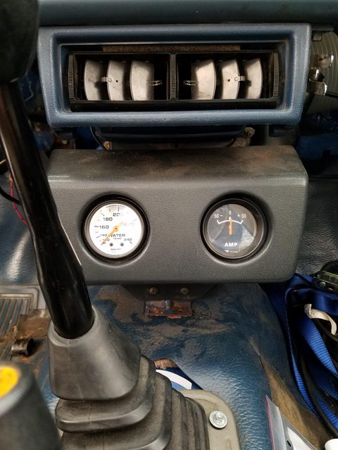
I didn't know 1980's had an ammeter...that could be an issue for your plans and may be part of the rough idle problem. I don't have a wiring schematic so I can say for sure. I think once you get more confidence with wiring/auto electrical, I suggest removing and/or isolating redundant wires.
The first document is as measured amp draw with the truck running at idle. Where possible I tested with only the truck and that load running/on.
The second part is, 1) the original fuse link colour, 2) the original wire colour to that fuse link. 3) the new breaker size I used to replace the fuse link. The loads have the re-fused value and the original Toyota value.
You may have to change some of these as I don't know how much power the EFI draws and the electric fuel pump. But you get an idea how much stuff draws and how over fused stuff is. As you can see, as I mentioned the fuse rating for the wipers is greater than the stalled draw of the wiper motor, thus my broken linkage. I did not measure the stalled draw, wasn't too keen to break the linkage again, but calculated it with ohms law. (I =E/R) None of these values has produced any nuisance blown fuses.
Those values in the ammeter explanation are for example only and not meant to be absolute. If you look at the file I attached you'll see at idle my trucks alternator with no loads on other than the ignition put out 6 amps. Subtract the ignitions load of 1.5 amps, and you will have a 4.5 amp charge on the battery. If I had an ammeter installed it would show a charge of 4.5 amps.
I didn't know 1980's had an ammeter...that could be an issue for your plans and may be part of the rough idle problem. I don't have a wiring schematic so I can say for sure. I think once you get more confidence with wiring/auto electrical, I suggest removing and/or isolating redundant wires.
Last edited by Old83@pincher; Nov 30, 2019 at 04:36 PM.
Dec 3, 2019 | 02:03 PM
#10
Thread Starter
Registered User
Joined: Sep 2008
Posts: 95
Likes: 37
Fuse and load ratings as promised
The first document is as measured amp draw with the truck running at idle. Where possible I tested with only the truck and that load running/on.
The second part is, 1) the original fuse link colour, 2) the original wire colour to that fuse link. 3) the new breaker size I used to replace the fuse link. The loads have the re-fused value and the original Toyota value.
You may have to change some of these as I don't know how much power the EFI draws and the electric fuel pump. But you get an idea how much stuff draws and how over fused stuff is. As you can see, as I mentioned the fuse rating for the wipers is greater than the stalled draw of the wiper motor, thus my broken linkage. I did not measure the stalled draw, wasn't too keen to break the linkage again, but calculated it with ohms law. (I =E/R) None of these values has produced any nuisance blown fuses.
Those values in the ammeter explanation are for example only and not meant to be absolute. If you look at the file I attached you'll see at idle my trucks alternator with no loads on other than the ignition put out 6 amps. Subtract the ignitions load of 1.5 amps, and you will have a 4.5 amp charge on the battery. If I had an ammeter installed it would show a charge of 4.5 amps.
I didn't know 1980's had an ammeter...that could be an issue for your plans and may be part of the rough idle problem. I don't have a wiring schematic so I can say for sure. I think once you get more confidence with wiring/auto electrical, I suggest removing and/or isolating redundant wires.
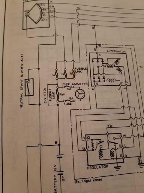
Here is a diagram with the ammeter. I believe it has been removed from the system. It is not tapped into the ALT. charge wire in any way, as you can see in my drawing, in my first post .
I have been working on removing unused wires as I feel comfortable. While working on this, I removed the emissions "computer" and a couple wires going from it to a plug related to the old carburetor.
The fuses and fuse holder should be here on Friday. Hopefully all goes well
Dec 3, 2019 | 03:59 PM
#11
Registered User
Joined: Jan 2016
Posts: 221
Likes: 37
From: Where Prairie meets Mountians
I switched to the smaller fuses after the broken windshield wiper transmission incident, simply to protect expensive and/or hard to find parts (like the linkage!) and after learning of that guys burnt truck. In the case of the wipers the motor stalled and continued to try to move the wipers and snapped the bushings but the fuse didn't blow.
I know the alternator in my 83 will put out 25 - 30 amps at idle...by memory. There is a test in the FSM, again by memory at idle turn on the high headlights and the defroster fan on high and it should put out about 25 amps + and have 13.5 volts or better...by memory!
The ammeter, first I guess an old dog can learn something new! I was a bit concerned it was still in some way still hooked up, if your confident its not in any way hooked up don't worry about it. FYI, the factory ammeter is what's called 'externally shunted' (apparently using that fuse link as the shunt) whereas most if not all after market ones are 'internally shunted'. Be warned if you replace the factory one with an aftermarket one it will not work correctly. Nothing disastrous will happen it just wont work right. Vis-versa will end up with a smoked meter!
In one sentence, an ammeter is basically a voltmeter which is measuring a very small voltage drop across a known calibrated resistance (a shunt), it's microvolts in fact.

Thread
Thread Starter
Forum
Replies
Last Post
95RedRun
General Electrical & Lighting Related Topics
11
Oct 27, 2013 01:43 AM
aaronk
General Electrical & Lighting Related Topics
5
Oct 9, 2007 04:52 PM


