When you click on links to various merchants on this site and make a purchase, this can result in this site earning a commission. Affiliate programs and affiliations include, but are not limited to, the eBay Partner Network.
1975-1978 Pickup Electric Fuel Pump Wiring Diagram & Info
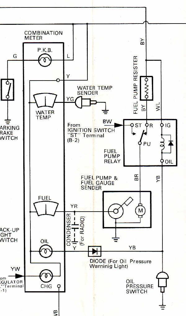
I had this diagram on file but thought it might be helpful to some out there, plus some info on rehabing the electric fuel pump circuit/system. This is the wiring diagram for the electric fuel pump circuit on 1975 to 1978 Pickups. It might also apply to 1979 to 1981 pickups with the 20R and electric fuel pump in the gas tank, and 1982 to 1984 & up 22R carbureted engines (NOT EFI). It might also apply to other models of the same era/years with the 20R engine, like the Celica or Corona. The wire colors below are for the Pickup; wire colors on other models may differ.
Wire Color Codes:
B - Black
W - White
Y - Yellow
G - Green
L - Blue
R - Red
BR - Brown
Wire Color with 2 Letters - 1st letter is the overall color of the wire, 2nd letter is the "stripe" color. Example: BR - Black with Red Stripe, WL - White with Blue Stripe, etc.
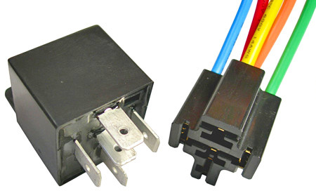
This diagram came in very handy for me when trying to rehab my fuel pump electric system. Original style fuel pump relays & resistors are no longer available from Toyota for the '75 to '78. I used a standard Bosch style 5 pin relay rated at 30-40 Amps & a wired socket as a replacement & it works fine. The Bosch style relay & wired socket look like this:
Electrically, the Toyota relay & the Bosch style relay operate the same way. I crimped on some female sockets to the ends of the wires on the wired socket & plugged each onto the male lugs in the original socket on the wire harness located under the center dash. This way I didn't have to hack up the original harness & retained the original plug. You could of course cut off the stock relay socket & splice in the Bosch style wired socket; that's up to you to decide. With the diagram it was hard to go wrong. All Bosch style relays will have a number next to each terminal pin. The pinout I used was:
Relay terminal to Stock Wire Color
85 - YB - Yellow w/Black Stripe - Oil Pressure Switch
86 - WL - White w/Blue Stripe
30 - BR - Black w/Red Stripe - Fuel Pump
87A - BY - Black w/Yellow Stripe - "RUN" from Ignition Switch, Fuel Pump Resistor
87 - BW - Black w/White Stripe - "START" from Ignition Switch
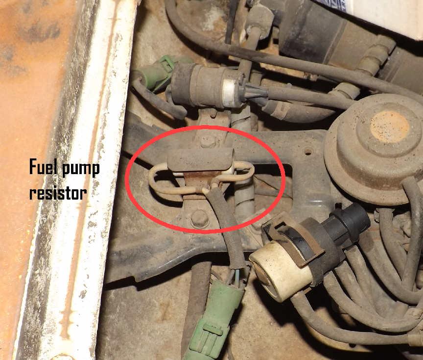
As for the resistor, the stock one was a ceramic power resistor rated at 1.4 Ohms and 10 Watts. Over time & with heat cycling the resistor can fatigue & get out of spec, especially when hot. It might measure/test fine with an Ohm meter "cold" but once it heats up the resistance will rise to a point where it "chokes off" a good deal of the voltage going to the fuel pump. My resistor measured exactly 1.4 Ohms cold, but when heated with a hair dryer it spiked up to 2.8 Ohms after only a few minutes. The tolerance on one of these working resistors shouldn't be anything beyond 10% (1.54 Ohms), so it definitely needed replacing.
I used a new aluminum cased power resistor in place of the old one and it works great. I installed it under the hold-down tab on the stock mounting plate & soldered it onto the stock wires. The resistor is located in the engine compartment, on top of the passenger side wheel well. Here are a few representative pics (they are not my exact parts, but posted to give you an idea of what they look like):
The resistor I used was from Mouser Electronics, who will let you order just the one piece, or sometimes you can find them at your local electronics shops. It looks like this:
Specs:
Manufacturer: ARCOL/Ohmite
Manufacturer Part # HS10 1R5 F
Mouser Part # 284-HS101.5F
1.5 Ohms, 10 Watts, 1% Tolerance
These resistors are military spec, moisture proof and are temperature rated from -67 degrees to 392 degrees F, so it's going to survive very well in an engine compartment. The aluminum case also acts as a heat sink so the resistor can easily get rid of any internal heat. The 1.5 Ohm rating is not exact to the stock 1.4 Ohms but it works fine. Pump volume does not suffer any. If you go looking for one of these resistors locally but can't find the exact spec, I recommend you keep it between 1.4 Ohms & 1.8 Ohms and at least 10 Watts; 20 or 25 Watts is fine as well, it'll just handle the power better with less internal heat. I've literally done DAYS of math on these, doing voltage drop calculations based on the different Ohm ratings, and considering the pump specs, the 1.4 to 1.8 Ohm range will work with no problems. Just do NOT go below 1.4 Ohms or you risk damaging your pump.
Glad you posted this. Im having fuel pump issues right now. The pump its self is brand new, just replace it. I tested the electrical harness at the tank and im getting a pulse of 3-12 volts, its not constant it goes up and down. Also took the relay off and tested the harness over there and im getting the same reading. Any idea what this means? Its supposed to be a constant current not a pulse.
I have not run into a "pulsing" voltage in the fuel pump circuit before, but you are right, voltage should be constant with very little, if any, variation. With that said, there has to be something else in the system that is causing this. With that said, some thoughts:
1. Can you let me know the exact year of the truck, engine type, and what items in the system you have checked/tested and how? More complete info can help track it down easier.
2. These trucks are now 35 to 40 years old & older. Many systems are probably overdue for service, "freshening up", reconditioning, or just plain old replacement. Which leads me to...
3. You say it's reading 3 to 12 volts and it's not constant, This would indicate a "connection" somewhere that is not solid. Possibilities:
A. Does the new pump actually pump fuel or not? The pump is grounded through a wire to the holder stalk, which then grounds to the tank, which grounds to the frame where it is mounted, and the frame is grounded to the Negative terminal of the Battery via a Ground Strap or Cable. Any one of these ground points/connections could be a cause. Did you inspect all of these and make sure they are ALL clean, with metal to metal contact? This is a common problem on older vehicles. Check them all, clean them all up & make sure everything is mounted securely. Also, re-check any crimp connections you may have made; it's easy to have a bad crimp on a connector & not know it. I prefer to solder them on.
B. Have you checked/tested your ground cables. Wire & cable in automotive applications do fatigue over time (especially those subjected to engine heat), and can develop resistance, or what could be happening in your case, have broken strands of copper inside the insulation that are making & breaking contact. That could account for the "not constant" voltage readings. The ground cables in my '78 were original. I tested them with an Ohm Meter and they read 0.3 Ohms or more. They should read zero or close to it. The extra resistance was causing a voltage drop to my whole electric system, as well as to the pump. Voltage at the pump should be 9-10 volts; I was getting 3.8 volts. Also the "battery clamp end" of the ground cable had half it's strands corroded away to nothing. Installed all new ground cables (mine has 2) & problem solved. Second ground cable is from rear of cylinder head to firewall.
C. Fuel Pump Relay - are you still using the original relay? If yes, it's over 35 years old & might have problems, usually pitted or corroded contacts inside. Pitting or corrosion of the contacts causes an uneven contact surface, which could reduce current carrying capacity, and even show up as variable voltage like you describe, due to the poor condition of the contacts.
The original stock relay should look like this: 1975-1978 Toyota 20R Fuel Pump Relay Original
The stock relays are no longer available, which is why I came up with using the Bosch Style Relay to replace it.
D. Did you test the Fuel Pump Resistor & check it's connections? Is it original? Again due to age & heat cycling in the engine compartment where it's mounted, these can also break down & get "out of spec" over time. Test it with an Ohm Meter. It should read no more than 1.4 Ohms cold and should not go above 1.6 Ohms Hot. I test them with a hairdryer or heatgun while they are hooked up to the Ohm Meter. A resistor that is bad or going bad will rise in resistance with heat, possibly "choking off" the voltage to the fuel pump. My original resistor read 1.4 Ohms cold, but once I heated it up, it went to 2.6 Ohms; not good. That's why you see the replacement solution in my original post.
IMPORTANT - YOU NEED TO HAVE THE FUEL PUMP RESISTOR IN THE CIRCUIT, DO NOT BYPASS IT TO RUN THE TRUCK. Stock style fuel pumps are not designed to run on the full battery voltage, and they will burn out in short order if you run them on battery voltage, without the resistor in circuit.
So basically and in general, check out EVERY ITEM in the system to be sure it's right & so you KNOW exactly what you are dealing with. I learned this the hard way. Shortcuts in vehicle repair are a sure fail so better to check it all & get it right the first time. Any model specific info you may not have I'm happy to provide, just ask. Let me know what you find in detail. We'll get it figured out.
Last edited by 13Swords; 02-11-2020 at 05:32 AM.
Reason: Spacing
Checked voltage for harness at the tank got a pulse from 0 - 8.05. Took relay off retested again got pulse from 0 - 005 volts.
Checked resistors got nothing 0 as you can see in this pic.
Disconnected the oil sensor and checked that got a reading of 1.96 volts.
I don't thing the ground wire is the original its in pretty good shape but I could replace it with a modern cable what gauge should it be 2 or 4? The ground is connected to the frame and then to the back of the smog pump should I connect it the same again?
The ground wire to the engine and cabin on the driver side, I have cleaned it and tighten it about a year a ago. It is a black wire with a yellow line through it, as you can see in the pic. I can replace it what gauge should it be? I also have another ground on the passenger side front of engine that connects to the smog pump, and engine mount.
Last edited by nottoshabi; 02-13-2020 at 02:40 PM.
8.05 Volts at the pump end of the harness is a bit low, but should be enough to run the pump if it's steady voltage. Again, pulsing voltage should not be present in this system. Relay voltage from zero to 0.005? 5/1000ths of a volt? No where near enough. What do you mean you took the relay off? Did you test for resistance on the relay itself? (See more info below on testing for resistance)
I still think your "pulsing" problem is the relay. You didn't let me know if your relay is original or not. Look at the pic I posted in the previous post & let me know about this. Bad contacts in the relay could be causing the "pulsing" problem.
IMPORTANT - You are measuring the resistor incorrectly, according to your pic. You have the meter set to DC Volts. You need to have it set to 200 IN THE OHMS RANGE (green area to the lower left of the dial). You can't measure resistance using the Volts range, only the Ohms range. More info; please read all of the following:
All resistance is measured in Ohms, not Volts. I see you have the same meter as I do (the $6 Harbor Freight job) which is fine, but there are a few things you need to know about it to get an accurate resistance reading. This meter is not "self zeroing", which means it does not account for the resistance in your test leads. The test lead resistance will be a part of any resistance reading you take on an item, and can give you a false reading, especially when measuring low resistance items like the fuel pump resistor, which is rated at 1.4 Ohms. Here's how to account for that. Set the Meter to 200 Ohms (200 mark just above the on/off switch). Turn the meter on. Touch your test probes together & take a reading. These meters will usually display a resistance of at least 0.03 Ohms or more, just from the test leads. Then measure resistance in the fuel pump resistor & take a reading. Then subtract the test lead resistance reading from that result to get the actual reading for the resistor.
If anything about this isn't making sense to you let me know & I'll try to make it as simple to understand as I can.
I do see several issues with your ground cables/wires. Your battery ground cable appears to be original (black with yellow stripe) and should go from the negative battery terminal to the passenger side motor mount. It can look in good shape but still be out of spec. I have no idea why you have a secondary cable to the smog pump. If anything draws a ground from the pump it should get it through the frame ground at the motor mount. The pump is basically connected to ground through it's mounting bracket.
What year is your truck? My '78 doesn't have a ground on the smog pump, but later years may have had them. Let me know.
Measure the resistance on that main ground cable, from cable terminal end to cable terminal end (NOT from the Battery Terminal or from the motor mount bolt). This way you will only be measuring the cable & it's terminals. If it's good you should get a reading of zero to 0.01 Ohms (remember to subtract the test lead resistance!) Anything above 0.01 Ohms resistance I recommend replacing the cable. 4 Gauge should be plenty thick enough. Have you cleaned the connection points for it at the battery terminal & motor mount? What do those look like?
The cylinder head to firewall ground cable also looks original. Clean off that dirt on the connections to bare metal on the terminal ends & measure it for resistance just like the battery ground cable. Again it should read zero or near zero resistance if good. I do not remember what gauge that one is, but do remember taking it with me to the hardware store to match it up & buy terminals to fit it. I ended up making my own ground cables, as there does not seem to be any new ones available from Toyota. Some parts stores will have some pre-made "universal" ground cables and those are OK as long as the wire gauge is the same, and if you can find the right length(s).
That's all I have at the moment. Let me know about those items I mentioned above & what else you find.
Everything makes perfect sense, your explanations are clear. In my previous post I talked about removing the relay. I actually unplug it, that's what i meant by removing it. It is the original relay, I can not seem to find any Bosch relays around me. I can only find ACdelco's for domestic cars. And the auto parts guy can't tell me what amperage they are.
I tested the resistor and got a measurement of 2.6 ohm's. I have not subtracted the 1.4 for the wire leads as you recommended. So that means its in the normal range, for a cold resistor? I have also changed the ground wires from battery to frame, engine to cabin.
OK, thanks for the clarification. It being the original relay I would strongly suspect that the contacts in it are worn, at the least, if not totally degraded & pitted, and not providing good transfer of energy. They also likely have some corrosion on the contacts from arcing, which is a natural thing that happens with them when they open or close. After 40 years & maybe hundreds of thousands of cycles, they do get worn out. So you can have an example of what this can look like, here's a pic of some arc-pitted contacts in a relay:
Relay Contacts Pitted from Arcing over time.
Those contacts are supposed to be smooth & shiny!
Not so sure your auto parts guy knows what he's doing, or he's too lazy to look. The specs on relays should be listed in his computer, and they are almost always printed on the relay itself; he just has to look. Also when I say "Bosch" relay, I do not mean an actual Bosch branded relay, but Bosch style relay. These are the most common type of relay and are made by many manufacturers. It doesn't have to be any particular brand of relay, it just has to be good quality. Any 5 Pin Bosch Style relay of quality that looks like the one I posted will work.
If you want to try to find a relay & pigtail socket locally, look for car audio shops, the ones that like to install those huge subwoofers in vehicles. They will usually have stock of those items, because they are always doing custom installs on mega sound systems that use tons of power, so they need the relays. You might also try any local repair shop that specializes in auto electrics. Just ask about a relay & pigtail socket for it with the specs I stated in the original post. 12 volt, 30 to 40 amps rating (will be marked 30A/40A). Relays just marked 40A or 40 AMP are fine too.
I also had trouble locating what I needed locally (which seems to be an ongoing trend in retail these days) so I got what I needed from Ebay. Here's a decent one that meets the specs: https://www.ebay.com/itm/2pc-12V-Car...sAAOxyjNlR4H~a
I've double checked (researched) the part for you & the quality is very good, plus you get TWO relays & sockets for that price shipped FREE! Gotta love Ebay.
RESISTOR - Easy math; 2.6 minus 1.4 = 1.2 Ohms. That is within spec for a cold fuel pump resistor. Stock spec for it is 1.4 Ohms, 10 Watts, 10% tolerance. Just me but I'd also hook it back up to the meter & test it with a hairdryer running on high, pointed at the resistor about 6 inches away, for a couple of minutes & watch to see if the meter reading goes up or not. This is to check for a weak or malfunctioning resistor. The meter reading can go up, but if it doesn't go much beyond 1.6 Ohms hot, the resistor is fine. Readings beyond 1.6 Ohms the resistor needs replacing.
A little update. Needed to change the multi meter the one I was using before was not mine. Bought an electrical kit and this one came with it.
I have installed a new fuel pump relay from Toyota brand spanking new. I'm still getting a pulse at the tank harness, it goes up to 20v and down to 2v. Big improvement from before. I'm also getting low reading when installing the fuel sending unit harness, pulse reading_1, pulse reading_2, pulse reading_3. It also looks in corroded condition so i'm going to replace the wires and clean the connections. Cause i'm getting 0 reading when reading the connections directly to the pump. I'm going to solder the connection that is made from a rivet, and replace the rest.
Where in the world did you get a NEW relay for a '78??? I've looked high & low for several years and they don't seem to exist for '75 to '78. Very curious. What's the part number?
I think I see something significant in your pics, 2 different things actually, both are very important.
1. You are measuring the wrong points to measure Fuel Pump Power. BOTH of those tabs are power connectors, but only ONE of them is for the Fuel Pump Power. I will explain. PLEASE READ THE FOLLOWING CAREFULLY.
In your 1st picture, the power connector for the Fuel Pump is the one you have the Red Probe on. The connector you have the Black Probe on is the power feed for the Fuel Sender. These are separate circuits.
The Fuel Sender is what makes your Gas Gauge work.
To properly measure Fuel Pump Harness Voltage (which is what you have been trying to check all along), you need the Red Probe exactly where you have it in the picture, BUT the Black Probe needs to be touching a solid ground point, like CLEAN bare metal on the frame of the truck.
Both circuits are normally grounded to the frame to make a complete circuit path so that electricity can flow.
The Fuel Pump is grounded to the Fuel Pump Stalk, using a wire connected to the small tab on the pump, then connected to the metal stalk by a screw.
The stalk grounds to the gas tank through the flange screws. The tank is grounded to the frame when it is mounted, The frame is grounded to the Battery Negative. Get the idea?
This is called a "common ground" system. It saves the cost & weight of running separate ground wires from the battery to every component. But it does depend on every component having a good clean ground point to the frame. That why clean & solid ground points are so important in vehicles.
My apologies if you already know any or all of this, but I'm taking no chances, and want it to be super clear.
2. Your meter setting is wrong. It looks like you are set to measure AC Voltage instead of DC Voltage. AC Voltage has a "pulse" to it, DC Voltage does not. Could it be that you have been measuring voltage on the wrong meter setting?
Nearly all voltages in vehicles (with some very specific exceptions) are DC Voltage.
Check the instruction manual that came with the meter. I couldn't find an online manual for your specific meter, but did find some that have similar markings.
The Range you are set to in your pics (second pic is clearest) has the V~ (wavy line) marking, and is for measuring AC Voltage. The Range with the "V", a straight line & 3 dots is for DC Voltage.
Try measuring the voltage on the other range & remember that the Black Probe needs to go to a good ground point. See if you entirely lose the "pulsing". Let me know about this & what results you get..
Your connector tabs don't look bad at all. They are solid copper & should clean up easily. I just used a Scotch-Brite green pad on mine (I do NOT recommend using sandpaper), or you can use a pencil eraser, works fine.
I suggest that before you modify anything, you make sure your meter is on the right measuring range, and that you measure the correct points I described above. No need to change anything if they are actually fine & working.
Any questions about any of this just let me know. I know it can be a slog to figure out how everything works but I'll continue to help you where I can.
I went to the Toyota dealership at the parts department and showed them this photo. They don't have it in stock but they can order it, expect it in about 2 days, maybe 3. I live in Los Angeles and there is a big car community over here, I can give you the number to the dealer ship if you are entrusted I'm sure they can mail you any part you need.
What I'm trying to do now is test the pump out side the tank so I don't spend time installing the tank to find out it does not work and have to drop the tank again. In this picture the multi meter has a spot for the 9v battery tester is just under the setting I have it on and that's why I have it on that side. What I have not posted is how I have been testing the harness. I just stick the multi meter prongs directly into the sockets of the harness that connect to the fuel sending unit. I will take a picture tomorrow, right now its raining and everything is wet. But reading your previous post about the fuel sending unit being ground to the tank, the pump to the unit, and the tank to the frame. The way I'm testing the harness is incorrect, I'm getting a pulse on the DC and AC setting of the multi meter, and I think is because I'm not connecting to a ground.
Once its dry I will rig up some sort of wire connection between the fuel sending unit, the harness and frame. My objective is to test that the pump works before I install it back in the tank. Unless you have have a better idea or work around for this? At this point I have changed the grounds, relay, and tested resistor with a cold motor. The pump should run, unless I'm missing something? I have noticed that in these vehicles the pump and the oil pressure sensor run on the same circuit. Would that cause the pump not to run if the sensor is defective? And if so how can I test it?
Last edited by nottoshabi; 02-22-2020 at 05:15 PM.
I'm going to be super interested in what your dealership comes up with in the way of that part. I've had several tell me that it is no longer made, and my extensive online research says the same thing. They may try to give you a newer version one from a later model, which actually could work. I haven't studied those as much due to the much higher cost over the Bosch style relay.
Last item first. Yes, the oil pressure sender is a part of the relay circuit, and is a safety feature. Here's how it works. If you look at the diagram, you see that there is a complete circuit from the "RUN" terminal of the relay to the fuel pump. The relay is in this condition when the engine is either cranking or running, AND the Oil Pump produces enough oil pressure to "open" the oil pressure sender, which is a basic switch. This de-energizes the electromagnetic coil in the relay & allows the contact arm to connect with the "RUN" side.
If for any reason the engine were to lose oil pressure (like in a crash or low oil), the oil pressure sender will "close", energize the coil, & click the contact arm over to the "START" terminal. This keeps the pump from sending fuel through broken fuels lines that might result from a crash, and prevents fires. This also allows the pump to run when you go to start the engine with no oil pressure (normal). It takes a few seconds of cranking or running to get oil pressure up. So basically, if your oil pressure sender is working, your "OIL" light should be on when the engine isn't running, but should go out a few seconds after starting the engine, or even a few seconds into cranking.
You are correct, if the oil pressure sender is defective and/or not working, the pump would run only on the "START" side. This presumes that the sender is defective and stuck in the "closed" position.
The oil sender is a simple switch that is either closed or open. You can easily test it with the Ohm Meter. It is located below the oil filter and should have one wire going to it, brown in color. The sender grounds through the block. Engine NOT running. Take off the wire connector, set Ohm Meter to 200 range, touch red probe to connector, touch black probe to a good ground. If the sender is closed like it should be, you should be reading continuity with zero Ohms resistance. If you get no reading at all (infinite resistance or "open circuit") the sender is bad. Testing for actual operation, you just watch the "OIL" light when cranking; it should go out after a few seconds, showing that the switch is responding to oil pressure.
I understand what you're saying about why you have the meter set the way you do, but I'm telling you it's not correct. The battery tester range and where it is on the meters face has nothing to do with whatever is next to it. It is a separate range entirely. Physical proximity does not determine function.
The range you are using is for AC Voltage and you are never going to get an accurate DC Voltage reading that way. Use the DC Voltage range to the left of the "OFF" position of the dial. Put it on 20. Again, refer to the Users Manual that should have come with your meter & read it.
I don't mean to yell at you or anything, but there is no sense testing things unless you are going to get accurate results. I don't want you to waste anymore of your time chasing down "pulsing" readings that may be caused by inaccurate meter range settings.
BTW - the "200" & "600" settings on the range you have been using is a dead giveaway that that is the AC Voltage Range & not the DC Voltage Range
If you want more convincing have a look at this: https://learn.sparkfun.com/tutorials...suring-voltage
Again, if you are only trying to measure voltage by probing the connectors in the relay socket on the harness, you're not going to get any results that tell you anything. You are right, you need to probe one harness connector & touch the other (black) probe to a good ground point, like a bare piece of metal under the dash.
If it were me, I'd just test for voltage on the Black/Yellow terminal in the relay socket, which is the "RUN" circuit.
- Set Meter for DC Volts
- Put Red Probe in socket terminal for Black/Yellow wire (Fuel Pump Resistor Circuit)
- Turn key in ignition to "RUN" (NOT "START"!)
- Touch Black Probe to a good ground point & read the meter
- If all is good, you should see a steady reading of around 9 volts DC.
Give this a try when things dry out & let me know what's happening.
The relays are the same kind, what i'm finding out about this truck is unless I have the exact part number they can search in their data base no one can get parts for it or know anything about it. Toyota systems do not go further then 1981, when the clerk hears anything earlier then that, they can't help.
It dried today so I was able to some testing. Cleaned up a small spot on the frame that the tank actually attaches to, used an alligator clip as a ground and tested the leads on the wire harness at the tank side. Still getting a pulse 1.27V, 5.94V. I tried to mimic the tank connection by connecting the resistor to the top of the sending unit with the alligator clip as you see in the pic. The voltage goes down from harness only, to sending unit by 2 whole volts, (Don't know if that's normal just thought I mention it). Also I have found this to be weird this wire gave a 0 reading the other was having some sort of life in it, but the one connected to the pump it self gave no sign of life. I looked at the oil sender it read infinite Ohm's. When I touched it with the leads the screen went blank. Disconnected the connection to the oil sender to see if it made a difference in the wire harness voltage and, it did not. I will be looking to get a new oil sender. If you know of a place please let me know, I don't think I will be having the relay luck from Toyota. Removed the relay and tested the yellow and black line and got a solid 11.4V
After the oil sender switch I don't think there is anything else for me to test/exchange except the voltage coming out of the harness at the front of the truck right out of the relay. If the pulse is still there what other alternative do I have? An external fuel pump mounted in the engine bay? I was thinking of running a whole new harness and put the fuel pump on a switch like track cars have. It will be an added security to the truck, but will make it a fire hazard. What do you say?
I hear you about parts guys not knowing much about the older vehicles. They just don't seem to keep that information in the computers. That new relay certainly looks correct & the parts number matches so it should work fine. At least now we know we have good contacts in it so one less thing to worry about.
Now I have to get even more specific. You wrote:
"Cleaned up a small spot on the frame that the tank actually attaches to, used an alligator clip as a ground and tested the leads on the wire harness at the tank side."
The "wire harness" part of that is a little confusing. Do you mean the connector at the tank that has two wires? It looks like it from the picture.
IF the wire you are checking is the one going to the Gas Gauge (Yellow with Red Stripe) and you are getting a reading of 1.27 volts pulsing, that is not unusual and does not indicate a problem with that circuit, Frankly you need to ignore that wire in trying to track down the fuel pump issue. The fuel sender/gas gauge circuit is completely separate for the fuel pump circuit. it has nothing to do with how the fuel pump operates.
The wire you need to be concerned with that feeds power to the fuel pump is the Black with Red Stripe wire. If that one is what is reading 5.94 volts*, that's a little low for pump voltage, but the pump should still work. Fuel volume & pressure should be good enough to run the engine.
*See Random Thought about Battery Voltage below.
Did you test voltage in this wire with the oil sender disconnected or connected? Did you have the key on "RUN"? Please test it with the oil sender disconnected & the key turned to "RUN" and see what voltage you get.
If it's still around the previous 5.94 volts, I'd suspect the fuel pump resistor is out of spec, & deserves a retest.
Again, don't be worried about the fuel sender side of this, it has nothing to do with the fuel pump circuit. The voltage going down from the gas gauge power feed to the fuel sender ground is normal.
The fuel sender is basically a variable resistor, so it is going to act like a voltage drop device, which is exactly what it is designed to do. We can get into the fuel sender later if you want, but we need to make sure your fuel pump circuit is right first.
Picture 5 - Fuel Pump Power Feed Terminal under Flange. If the tank connector is in it's place on top of the Flange, to check for voltage at this point you need to have the oil sender disconnected and the key on "RUN". Otherwise you will get a 0 (zero) reading. More on this next....
If you checked resistance of the oil sender with it's wire disconnected, and it still read infinite resistance (screen going blank), that means the sender is in an "open" condition (no voltage can flow. That does mean the sender is bad.
The oil sender is supposed to be in a normally closed condition (voltage can flow) when the engine is not running (no oil pressure).
Again just to be clear on testing this item - Meter set to 200 Ohms Range, Black Probe to body of sender, Red Probe to Terminal of sender. Here's a pic of one for reference: 20R Oil Sender
It would more than half-way suck if all along the oil sender has been the source of the fuel pump problem. But it's bound to be original (these things almost never break) so replacing it with a new one is still a good idea. They do not cost very much at all.
Most parts stores will not have them in stock due to the age, but some will have them listed in their databases and can special order them (usually charge you excessive shipping too!). If it were me I'd just order one up from Rock Auto: https://www.rockauto.com/en/catalog/...+/+switch,4588
Either of the 1st two shown are good units (WVE - Wells Vehicle Electrics & Standard Motor Parts), I prefer STANDARD brand parts because they have never let me down.
IMPORTANT NOTE - Only order/buy the oil sender with the SPADE TERMINAL. The "round type" of sender shown with the "button type" terminal will NOT work.
Also, these senders usually come with thread sealer already on them. Do NOT add any extra thread sealant when installing.
I do not have an install torque spec for this part. What I do is thread it in by hand using my finger until it stops, then give it 1/4 to 1/2 turn with a wrench, just like an oil filter.
* Random thought - Have you checked your battery's voltage? Your comment about the 11.4 volts on the Yellow with Black wire makes me wonder a bit. Check the battery with your Volt Meter. If the battery reads anything less than 12.5 volts, it's either in need of a charge or the battery is bad.
A battery with lower than normal voltage is going to "skew" all your meter readings down the line.
Let's not get too far ahead of ourselves on external fuel pumps. Get that new oil sender in & retest first. As long as the wires in your harness are intact it should all work as designed.
I do appreciate that you are thinking ahead on alternatives though. I have seen some people with this model truck resort to the external pump, some of them doing it "wrong" though. Just basic info on it. There is no need or reason to mount an electric fuel pump in the engine bay, and you are right, it's a safety & fire hazard to do so. Besides, electric fuel pumps work best when mounted/placed as near to the tank as possible. That way they only have to "draw" gas through a very short length of fuel line, and as long as the pump is decent in quality, there should be no loss of fuel pressure at the engine side. The hardest amount of work the pump has to do is the "drawing" or negative pressure side of it. That's one of the reasons why Toyota (and a lot of other vehicle makers) placed the pump in the tank. The other reason is that the gas actually acts like coolant and lubricant for the pump.
Keep at it, you're going to get this to work one way or the other. I'll still be here. PS Your inclusion of the pics is very helpful, thank you for making the effort!
Last edited by 13Swords; 02-26-2020 at 05:57 AM.
Reason: Added PS
First of all, I can not express in words the gratitude I have for your patience and detail in helping out wit this issue. You are more knowledgeable then the last 2 mechanics I took the truck to. Thank you so much for this, I'm so grateful for you, if you lived in the LA area I would buy you a beer or 2, or 10.
You wrote: The "wire harness" part of that is a little confusing. Do you mean the connector at the tank that has two wires? It looks like it from the picture.
IF the wire you are checking is the one going to the Gas Gauge (Yellow with Red Stripe) and you are getting a reading of 1.27 volts pulsing, that is not unusual and does not indicate a problem with that circuit, Frankly you need to ignore that wire in trying to track down the fuel pump issue. The fuel sender/gas gauge circuit is completely separate for the fuel pump circuit. it has nothing to do with how the fuel pump operates.
Yes that's exactly what I mean when i'm referring to the harness. The wire connections that connect to the pump assembly at the tank, the pump and the fuel sender is part of it. The Yellow & Red Stripe is the only one giving voltage (the pulse), the other wire is completely dead, nothing coming out of it. Here is a pic with the pump assembly connected to it and the wire is dead. I don't have a pic of the harness and the meter connected to it. I was always under the impression that the pump and sender worked under the same circuit. Reading your last post has made me realize otherwise.
You wrote: Did you test voltage in this wire with the oil sender disconnected or connected? Did you have the key on "RUN"? Please test it with the oil sender disconnected & the key turned to "RUN" and see what voltage you get.
If it's still around the previous 5.94 volts, I'd suspect the fuel pump resistor is out of spec, & deserves a retest.
Yes. I tested with key in the run position and oil sender connected or disconnected, pulse and voltage was not affected at the harness end. Yellow & Red Stripe had the same pulse as before, Black with Red Stripe wire. Dead. So far changing the ground wires, relay, connecting or disconnecting the oil sender has had no effect on the Black with Red Stripe wire being dead.
You wrote: If you checked resistance of the oil sender with it's wire disconnected, and it still read infinite resistance (screen going blank), that means the sender is in an "open" condition (no voltage can flow. That does mean the sender is bad.
The oil sender is supposed to be in a normally closed condition (voltage can flow) when the engine is not running (no oil pressure).
The oil sender connected and disconnected with the key in the run position does not read a difference in the meter, screen is blank on both attempts. I will be ordering a new one of these from rock auto.
You wrote: * Random thought - Have you checked your battery's voltage? Your comment about the 11.4 volts on the Yellow with Black wire makes me wonder a bit. Check the battery with your Volt Meter. If the battery reads anything less than 12.5 volts, it's either in need of a charge or the battery is bad.
A battery with lower than normal voltage is going to "skew" all your meter readings down the line.
Battery is good, it does read 12.5 with the meter and I also took it to the auto parts store to have it checked. Had the same tough when the relay connection test read 11.4V
So to recap:
When i'm talking about the harness I mean the wire connection that is at the tank side. The Yellow & Black wire gives a pulse, it has gotten stronger since replacing the relay almost double. The Black & Red Stripe wire has been dead since we started this wild goose chase. Connecting or disconnecting the oil sending unit has made no change in the Black & Red Stripe wire having life.
I will be purchasing a new oil sender and a new resistor. Don't want to wait another week to find out the resistor is also bad and needs changing.
You are most welcome, that was the whole point of my posting the info about the relay replacement & the fuel pump circuit. I may know more about this than those mechanics, but only because I went through the mill on this myself in fixing mine. I didn't want anyone else to have to blindly go through all of that.
Glad we're on the same page now about what you meant by the wire harness, it makes things clearer. The reason I wanted you to test the fuel pump power wire at the tank end, with the oil sender disconnected, was basically a test of that power circuit for voltage. With the oil sender disconnected, the relay should be on the "RUN" side (see schematic diagram in original post).
I know you said the wire was "dead" in you testing, which looks like you have done correctly from your descriptions. However there are two more things to check that occurred to me in looking at the pic, and I do not know if you have done this yet.
1. Have you probed connector in the socket itself when checking for voltage? By this I mean the female terminal in the socket that is connected to the Black with Red Stripe wire.
I ask this because I want you to eliminate any possible "disconnect" problem that might be in the terminal on the flange.
2. Same thing, different test. You can use your meter to check for continuity on that flange terminal, to make sure it can pass voltage through it.
Just set up your meter for resistance (Ohms, 20 Range) and put a probe on each side of that terminal. If good it should show a reading of zero or near zero. Also, wiggle the terminal around a bit while you have the probes on it & watch the meter for any changes at all. If you see any variations in the meter while doing this, something in the terminal itself is broken.
This could be a cause of an intermittent circuit or a dead circuit.
Just trying to think of eliminating as many possible faults as possible. This would be so much easier if I was there! But we'll soldier on.
Good work on having the battery checked.
No need to wait another week, go ahead & test the resistor. You can easily unbolt it from the truck for "bench testing" if you want to. I still recommend doing the "stress test" on it with the hair dryer, heating it up while it's connected to the meter. If the resistor is weak that test will show it. It sure did on mine.
If you find out (or even just want to replace anyway) the resistor, see my original post for recommendations on a correct part. You can't get the Toyota OEM resistor unit new anymore, they are long discontinued. But there is always a way to get something to work, and work right.
I know this feels like "wild goose chasing" but I can tell you that if it is your final goal to have a good running truck, all of this will help you get there. Replacing those parts & components is not a waste of money or time, but an investment in some future years of use. Like I said before, giving the age of these vehicles, they were most likely overdue to be replaced anyway.
It's been over two years since I did all this to mine, and it runs great without a hiccup.
More Random Thoughts -
1. Have you cleaned the connectors (Relay Connector, Tank Connector, Resistor Connector)? Again, they are 42 years old and very likely to have some crud in them that could prevent a good connection. Especially the resistor connector & tank connector, as they "live" outside and are subject to moisture & road dirt.
At the very least I spray some WD-40 into the sockets & blow them out with compressed air, if possible, if not let air dry. I have also used spray electrical contact cleaner, WD-40 brand also makes some of this, & CRC is the old go-to brand of it. You can find it in parts stores.
Even swishing the connectors around in a cup of isopropyl alcohol is better than nothing & takes literally no time to do.
2. Related - Check your fuse box. Sometimes the fuse holders will develop some corrosion or even metal oxides that could affect connection between the holders & fuses. If you have a connection problem there, everything "down-stream" (like the fuel pump circuit, and everything else for that matter) might show a problem.
There can even be built-up copper oxide on the terminals on the BACK of the fuse box where the main harness connectors are, but this is less likely. Just trying to think of everything here.
Guess who is up and running? What I have noticed is the wire that feeds the fuel pump relay is lacking in volts. I did some meter testing at the relay and found out that i'm getting 0.12V out of the Yellow & Red wire, which should feed the relay and pass through to the pump. If I connect 12V to the Black & Yellow wire which runs to the pump it self, then the pump runs. So I connected a wire from the cigarette lighter to the relay female connector and the truck runs. I'm not going to drive it around just yet at least I don't have to push it for street cleaning.
I changed the oil sensor and there are diffidently ohm reading now. I get 0.0 with the key in the OFF position and 7.7ohm with the key in the ON position.
In the female relay connection the wire that i'm getting 0.12V is the Yellow & Red in the book diagram this wire is connected to the fuel gauge in the dashboard and goes to the fuel sending unit. The fuel gauge has another wire Red & Light Purple this is connected to the back up light switch, and also connected to a heater gauge fuse. The fuse is fine I'm going to check the connection behind it tomorrow. Other then that I don't see why i'm not getting any voltage at the relay end? This seems to be the problem there is no voltage going to the relay and passing on to the pump.
I thought I covered this before but maybe I didn't.
The Yellow/Red wire is NOT a power feed for the relay or fuel pump. It is for the fuel sender ONLY, which is what makes your gas gauge work. It has NOTHING to do with the operation of the relay OR the fuel pump. It is a separate circuit and is not a part of the relay circuit at all.
The correct wire that feeds power to the relay for the fuel pump is the Black/Yellow wire coming from the Fuel Pump Resistor (look at the diagram).
What I would want to check is the continuity of the Black/Yellow wire, from the resistor to the relay socket, to see if the wire is actually intact. You're going to need some extra wire to do this. Disconnect the fuel pump resistor connector and look at the wires going to it to find the Black/Yellow wire.
Strip the insulation of the end of some extra wire, twist the end & push the bare wire end into the connector socket for the Black/Yellow wire. Run the other end of the extra wire into the cab & strip the insulation off that end. You're going to use that end as a contact point for one of your meter probes.
Set the meter to 20 ohms resistance range. Connect one probe to the extra wire end. Probe the relay socket on the Black/Yellow wire connector. This should complete the circuit to test for continuity.
If you get a reading of zero or near zero resistance, the wire is intact and should work. If you get no reading at all, the wire is broken somewhere between the resistor connector & the relay connector and needs to be found & fixed.
OK on the oil sender. Did you hook the oil light connector back up to it (connector with brown wire)? This isn't clear. If you did hook it back up, did the oil light go out once you got the truck running? If the oil light did go out with the engine running, you have no further problems there.
The sender & oil light circuit are simple; they either work or they don't, so don't get too hung up on the ohm readings.
Again, forget the Yellow/Red wire. It has nothing to do with the fuel pump.
The correct wire that feeds power to the relay for the fuel pump is the Black/Yellow wire coming from the Fuel Pump Resistor (look at the diagram).
What I would want to check is the continuity of the Black/Yellow wire, from the resistor to the relay socket, to see if the wire is actually intact. You're going to need some extra wire to do this. Disconnect the fuel pump resistor connector and look at the wires going to it to find the Black/Yellow wire.
Strip the insulation of the end of some extra wire, twist the end & push the bare wire end into the connector socket for the Black/Yellow wire. Run the other end of the extra wire into the cab & strip the insulation off that end. You're going to use that end as a contact point for one of your meter probes.
Set the meter to 20 ohms resistance range. Connect one probe to the extra wire end. Probe the relay socket on the Black/Yellow wire connector. This should complete the circuit to test for continuity.
If you get a reading of zero or near zero resistance, the wire is intact and should work. If you get no reading at all, the wire is broken somewhere between the resistor connector & the relay connector and needs to be found & fixed.
The resistor has 2 Black & Yellow wires going to it. Then they go into the wrapped black wire bundle that you see in the bottom of the pic. I see a Black & Yellow wire connects to this part don't know what this is. It has 2 vacuum lines one connects to the canister and the other somewhere under the carb. When I did a continuity check between the mystery part and the resistor I got a zero reading when connecting the Black & Yellow wires. The other wire I don't know where it goes, it gets wrapped up with the others. The diagram does not say anything about the second wire. I thought it went to the starter cause there is another Black & Yellow wire connecting to the starter as well. I did the continuity check between resistor and starter, and I got nothing. So where does that wire go, or come from? The wires between resistor and relay are working but what powers the resistor? I think if we find that, we find the root of my problem.
I did the continuity check as you recommended, from the resistor to the relay end. One wire I got a zero reading (GOOD) and the second wire I got nothing.
Originally Posted by 13Swords
OK on the oil sender. Did you hook the oil light connector back up to it (connector with brown wire)? This isn't clear. If you did hook it back up, did the oil light go out once you got the truck running? If the oil light did go out with the engine running, you have no further problems there.
The sender & oil light circuit are simple; they either work or they don't, so don't get too hung up on the ohm readings.
Yes the oil light has turned off as soon as the truck started running.
 11-14-2019, 07:01 AM


 What I have noticed is the wire that feeds the fuel pump relay is lacking in volts. I did some meter testing at the relay and found out that i'm getting 0.12V out of the Yellow & Red wire, which should feed the relay and pass through to the pump. If I connect 12V to the Black & Yellow wire which runs to the pump it self, then the pump runs. So I connected a wire from the cigarette lighter to the relay female connector and the truck runs. I'm not going to drive it around just yet at least I don't have to push it for street cleaning.


