

Toy or Bug?
 Jun 18, 2011 | 08:48 PM
#21
Registered User
Joined: Jan 2007
Posts: 6,106
Likes: 27
Thanks! Got banned again I did.
Atleast this time it wasn't my fault...but I'm not at liberty to discuss that in detail.
Better than bein' throwed in jail for no reason though. Been there, done that. Everything else kinda pales in comparison, trust me.
Atleast this time it wasn't my fault...but I'm not at liberty to discuss that in detail.
Better than bein' throwed in jail for no reason though. Been there, done that. Everything else kinda pales in comparison, trust me.
Last edited by MudHippy; Jun 19, 2011 at 03:24 PM.
Jun 19, 2011 | 11:00 AM
#22
Registered User
Joined: Jan 2007
Posts: 6,106
Likes: 27
O.k., I'm still a little confused here on the COR deal. Maybe you can shed some light on this.
A) Where's the capacitor/condensor in that diagram? Which I've cross-checked to see if it's right, and it is like every other one I can find. Because I'm 100% sure that there is one in there. But which I obviously don't know why it's there for, as I spoke too soon on that also.

Looks like this one, but green.
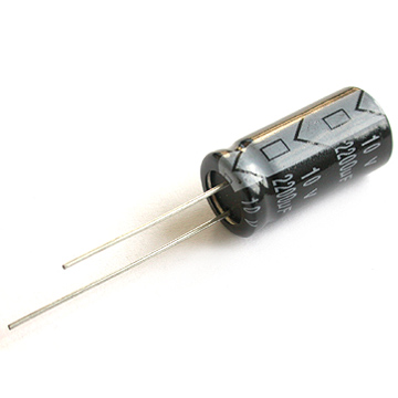
B) Where's the other coil/winding inside the COR? I'm 100% sure there's only one of those too.

If you don't believe me on those, I'll tear it open again and take a pic I guess. There's 5 I/O terminals/pins, 1 relay(coil/winding and armature + contacts), 1 capacitor/condensor, and 1 resistor.

Wiring and wiring diagrams are not my strong suit...obviously.
A) Where's the capacitor/condensor in that diagram? Which I've cross-checked to see if it's right, and it is like every other one I can find. Because I'm 100% sure that there is one in there. But which I obviously don't know why it's there for, as I spoke too soon on that also.
Looks like this one, but green.
B) Where's the other coil/winding inside the COR? I'm 100% sure there's only one of those too.
If you don't believe me on those, I'll tear it open again and take a pic I guess. There's 5 I/O terminals/pins, 1 relay(coil/winding and armature + contacts), 1 capacitor/condensor, and 1 resistor.
Wiring and wiring diagrams are not my strong suit...obviously.
Last edited by MudHippy; Jun 19, 2011 at 11:28 AM.
Jun 19, 2011 | 11:33 AM
#23

Actually 'MudHippy', not to be snippy, but there IS a difference between a regular relay and the COR (CIrcuit Opening Relay) I've had them all apart as well, the 1990 4runner COR HAS a capacitor, unlike your basic relay, as in your handy diagram, for say a flasher or headlight relay which goes without any capacitor. Moreover I've looked at several similar vehicles (same engine, same everything) and they are all different from each other so far.
Though, as I already said, and you reiterated, I don't believe it has any bearing on the VW mimic issue.
"To my point then. Since it's bypassed, all you've done is taken that relay/switch out of the power circuit to the computer. Which doesn't explain ANY of the codes you're getting. By the sounds of it, you've either got a fried ECU/ECM, and/or some serious issues with your VAFM that need to be addressed. And if it's been like this since before the COR died, how can it have anything to do with that anyways?"
Maybe in your haste you didn't notice I said "... 'off and on' before the C.O.R. died."
I appreciate that you are trying to help but I could do without the condescension.
- http://www.4crawler.com/4x4/CheapTri...ORelayLocation
- http://www.4crawler.com/4x4/CheapTri...shtml#FuelPump
Basically it is like 2 relays in one. The one side is set up to be driven from a logic signal from the ECU and thus is a little different internally and the other is set up to be driven by the closing of the Fc contact inside the AFM.
Last edited by 4Crawler; Jun 19, 2011 at 11:36 AM.
Jun 19, 2011 | 12:05 PM
#24

Thread Starter
Registered User
Joined: Jun 2011
Posts: 8
Likes: 0
MudHippy, please, don't get me wrong... I really do appreciate the help you are trying to give.
Yes, there is a green capacitor in there which had its leads corroded off (the reason I brought it up in the first place). And as we've been over already, I don't believe it has much, if anything, to do with the problem. So enough talking in circles about something which most likely has nothing to do with it.
Why the VW issue? Any idea?
Jun 19, 2011 | 12:09 PM
#25
Registered User
Joined: Jan 2007
Posts: 6,106
Likes: 27
Now I get it as far as there actually being 2 coils/windings. But the windings aren't seperate. It's really only 1 winding doubled(or a double winding maybe?). I truly don't get wiring diagrams I guess. Because I'm not seeing how they are connected in the diagram. It looks like 2 circuits to me. But whatever, because that's not the way it really is. 2 unshielded wires/conductors wound together constitutes an electrical connection last I checked.


As far as that capacitor/condensor, it's directly inline with the resistor. Why, as in what for, and why not shown on the diagram? You tell me.
As far as that capacitor/condensor, it's directly inline with the resistor. Why, as in what for, and why not shown on the diagram? You tell me.
Last edited by MudHippy; Jun 19, 2011 at 03:31 PM.
Jun 19, 2011 | 12:26 PM
#26
As noted below:
- http://www.4crawler.com/4x4/CheapTri...ORelayLocation
Those added components are likely there to soak up the electrical voltage spikes you inherently get with an inductor (i.e. the relay coil) when switching it on and off with a solid state circuit (i.e. the ECU).
- http://www.4crawler.com/4x4/CheapTri...ORelayLocation
Those added components are likely there to soak up the electrical voltage spikes you inherently get with an inductor (i.e. the relay coil) when switching it on and off with a solid state circuit (i.e. the ECU).
Jun 19, 2011 | 12:45 PM
#27
Registered User
Joined: Jan 2007
Posts: 6,106
Likes: 27
Gotcha. Now I get that part, and the other even better too...I think. Basically, they aren't important enough details for acquiring an understanding of the designed function/layout of the circuit(s), to justify cluttering up the EWD with their presence. "So let's just pretend they aren't there", so to speak. Or to put it another way, "they aren't relevant to the EWD, so simply disregard them". "Them/they" being the capacitor, and the spliced connection of the 2 coils/windings, in this case. The resistor, or lack there of, was chosen as the distinguishing characteristic of the 2 coils/windings. And that's all you really need to know as far as the wiring of those 2 circuits in the COR are concerned. There's no need to show the capacitor in the one circuit on the EWD, since it's part of the same circuit as the resistor(which is shown plainly). And the fact that they're spliced, 2 coils/windings-in-1 in this instance, would be why you need to be able to tell one from the other in the first place.
See...I ain't so dumb. Just give me a chance...I'll catch-on quick(ish).
Gotcha(and your welcome). Except on what's causing the issue still. I'd check the VAFM and/or ECU, and I'll add, the corresponding wiring/connections. But I sorta said that already...so there I go talking in circles again...
Now I get that part, and the other even better too...I think. Basically, they aren't important enough details for acquiring an understanding of the designed function/layout of the circuit(s), to justify cluttering up the EWD with their presence. "So let's just pretend they aren't there", so to speak. Or to put it another way, "they aren't relevant to the EWD, so simply disregard them". "Them/they" being the capacitor, and the spliced connection of the 2 coils/windings, in this case. The resistor, or lack there of, was chosen as the distinguishing characteristic of the 2 coils/windings. And that's all you really need to know as far as the wiring of those 2 circuits in the COR are concerned. There's no need to show the capacitor in the one circuit on the EWD, since it's part of the same circuit as the resistor(which is shown plainly). And the fact that they're spliced, 2 coils/windings-in-1 in this instance, would be why you need to be able to tell one from the other in the first place.See...I ain't so dumb. Just give me a chance...I'll catch-on quick(ish).
MudHippy, please, don't get me wrong... I really do appreciate the help you are trying to give.
Yes, there is a green capacitor in there which had its leads corroded off (the reason I brought it up in the first place). And as we've been over already, I don't believe it has much, if anything, to do with the problem. So enough talking in circles about something which most likely has nothing to do with it.
Why the VW issue? Any idea?
Yes, there is a green capacitor in there which had its leads corroded off (the reason I brought it up in the first place). And as we've been over already, I don't believe it has much, if anything, to do with the problem. So enough talking in circles about something which most likely has nothing to do with it.
Why the VW issue? Any idea?
Except on what's causing the issue still. I'd check the VAFM and/or ECU, and I'll add, the corresponding wiring/connections. But I sorta said that already...so there I go talking in circles again...
Last edited by MudHippy; Jun 19, 2011 at 04:07 PM.

Thread
Thread Starter
Forum
Replies
Last Post
IntoTheVoid
Trip-Trail Reports & Photos
41
Oct 24, 2015 04:54 PM
JookUpVandetti
86-95 Trucks & 4Runners
8
Sep 17, 2015 09:25 PM
3tc, 6al, 8591030050, 8591035010, 85910a, 93, capacitor, capacitors, circuit, condenser, corolla, diagram, difference, msd, opening, relay, replace, supper, test, toyota


