
Speed/Odo not working code 42
 Jun 27, 2010 | 01:52 PM
#1
Thread Starter
Registered User
Joined: Jun 2010
Posts: 70
Likes: 0
Speed/Odo not working code 42
I've already searched and looked at the threads on this topic but none of them helped or the pictures werent there anymore.
I have a 1995 4runner. My speedometer and odometer stopped working so i pulled the codes and it gave me a code 42. I also had codes 14,21, and 25 but those aren't related, but is it bad to be driving with a code 25(air/fuel too lean)? Anyways, I don't know where to start because I don't know which cable the speedo cable is on the transfer case and I also dont know which one the VSS is. My overdrive light is also flashing occasionally and cruise control doesn't work. Any help/pictures would be appreciated.
VSS= Vehicle Speed Sensor
Last edited by boogieboarder; Jun 29, 2010 at 11:22 AM.
Jun 29, 2010 | 07:23 AM
#4
Registered User
Joined: Jun 2010
Posts: 61
Likes: 0
Apparently only we care. I do believe the 42 code refers to the vss which is connected at the top of the transfer case. I also believe all of those symptoms point to the vss, but I too was just looking for some confirmation from someone who has done this before dropping the money on a sensor.
Jun 29, 2010 | 09:23 AM
#5
Registered User
Joined: Sep 2005
Posts: 8,656
Likes: 16
From: NW Ark on wooded ten acres...Ozarks at large!
What are you guys calling the VSS? I'm just not familiar with that term.
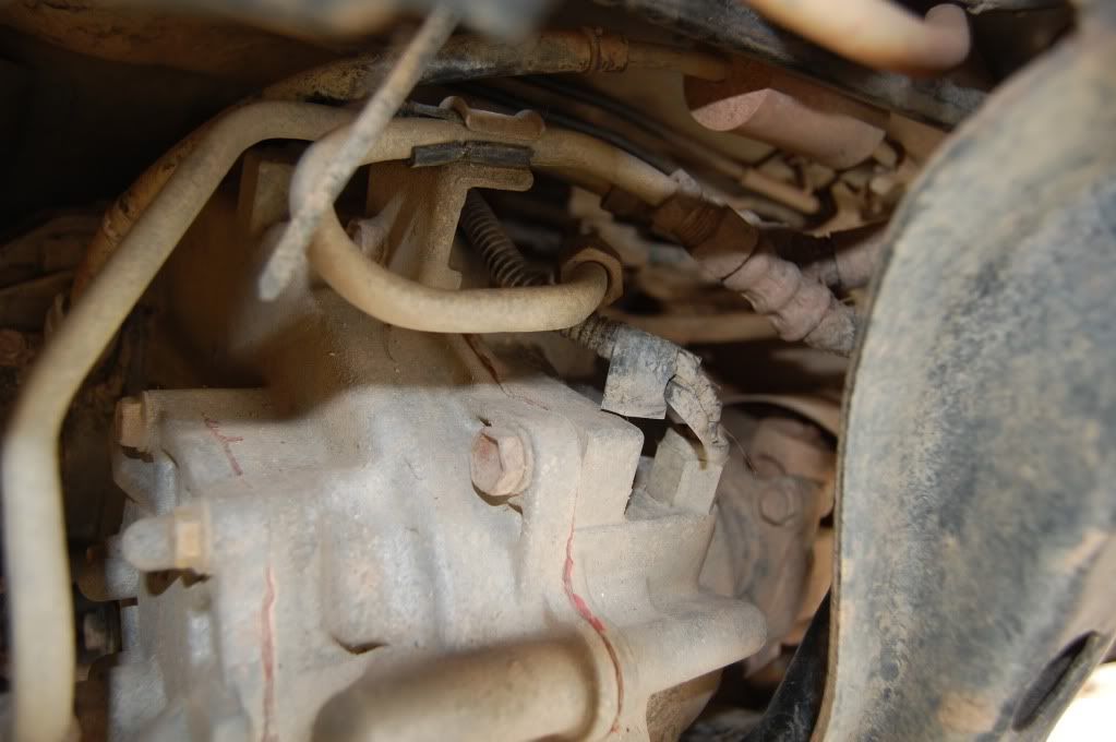
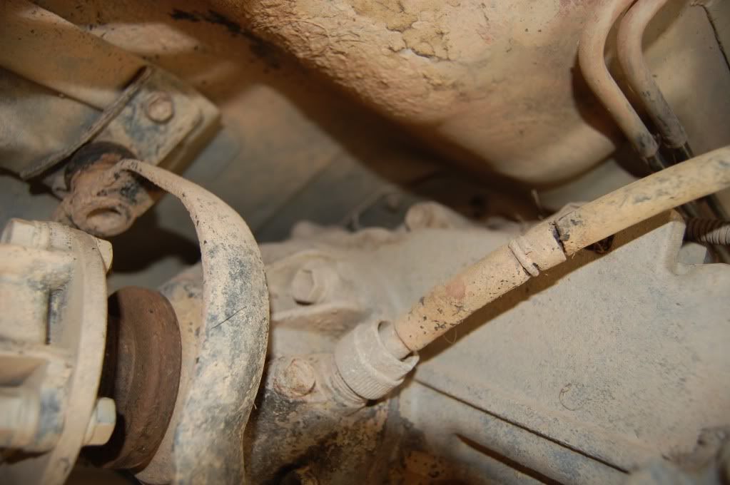
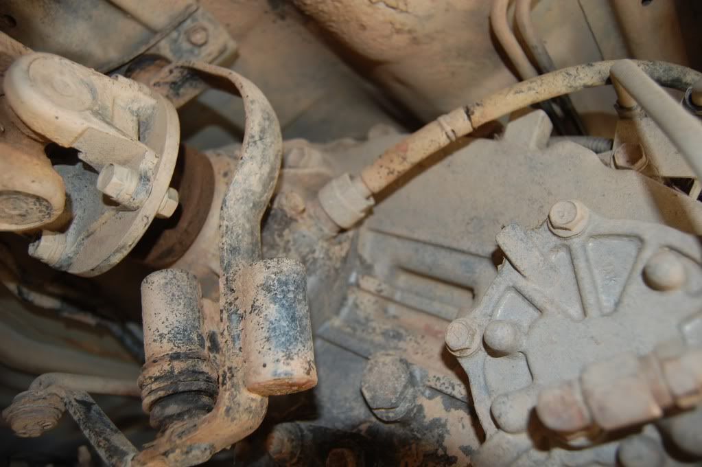
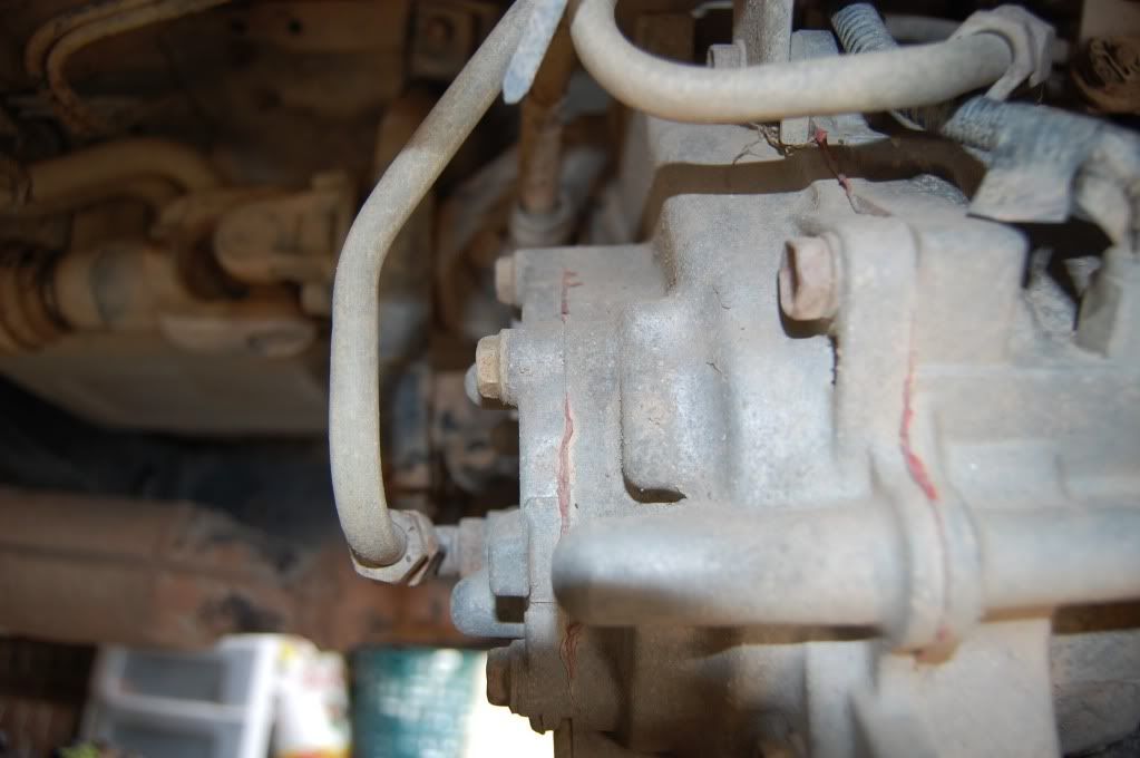
Anyway, code 42, according to my info sources, states speed sensor circuit. The O/D comes on when there is an issue for the transmission. In this case, your code 42. The speed sensor helps to control EFI and ECT (electronically controlled transmission) operation. Boostinchick had a thread about this a while back. I'll see about finding it. So, if it's the speed sensor I'm thinking about, and if your vehicles are no earlier than atleast '92, you won't have a speedo cable. You'll have a sensor located on the end of the transfer case, pass. side, with an electrical connection to it. There is a way to test the sensor that's very simple, though I forget the details, at the moment. I know I've talked about it other threads and may have even started my own about it, but I'll have to find that, as well.
Symptomatically speaking, this is the same problem I had a while back when the speed sensor went out on my wife's 4rnr. The cruise control. speedo, tach, odo, and trip meter stopped working right......maybe even altogether. It's been a while, so not sure. And, the vehicle also stopped running well. Anyway, replaced the sensor and that fixed that.
More details to come....
Jun 29, 2010 | 09:47 AM
#7
Registered User
Joined: Sep 2005
Posts: 8,656
Likes: 16
From: NW Ark on wooded ten acres...Ozarks at large!
Listen, boogieboarder, I don't know what kind of search you ran, but I just ran one using the simple key words "speed sensor" and "code 42" and turned up this thread. It's the one I'd mentioned with Boostinchick, but it's complete with discussion and a diagram. I don't know how you could've missed it. Anyway......
https://www.yotatech.com/forums/f116...e-42-a-161166/
BTW, I don't care what scope103 said about an ohm meter not helping. In fact, I started to post and debate the statement, but you'll see I just edited and said "nevermind". I only mentioned this because I thought the contradiction might be a source of confusion. Obviously using an ohm meter will work because that's the way I did it.........and, it worked!
Anyway......https://www.yotatech.com/forums/f116...e-42-a-161166/
BTW, I don't care what scope103 said about an ohm meter not helping. In fact, I started to post and debate the statement, but you'll see I just edited and said "nevermind". I only mentioned this because I thought the contradiction might be a source of confusion. Obviously using an ohm meter will work because that's the way I did it.........and, it worked!
Last edited by thook; Jun 29, 2010 at 09:58 AM.
Trending Topics
Jun 29, 2010 | 11:05 AM
#8
Thread Starter
Registered User
Joined: Jun 2010
Posts: 70
Likes: 0
Thanks everyone, i'm not sure how i missed that thread haha but anyways, my 95 does have a speedo cable, they switched it back to a cable for the ninety five.
Its raining right now but illl check it later and then maybe go to a junkyard and try and pull a sensor off. Im not sure if a sensor from a different year would fit though because I think the 92-94 runners had an electrical speedometer or something like that so would the sensor be different from my cable speed sensor?
My 4runner is shifting normally also, would that mean anything? Alot of people who have had speed sensor problems have had their 4runner shift bad/wrong times.
heres a link from rockauto:http://www.rockauto.com/catalog/rafr...937619-7445759
anyone know what the difference is between the 80 dollar one and the 260 dollar one?
which one is the right one?
Last edited by boogieboarder; Jun 29, 2010 at 11:11 AM.
Jun 29, 2010 | 11:28 AM
#9
Registered User
Joined: Sep 2005
Posts: 8,656
Likes: 16
From: NW Ark on wooded ten acres...Ozarks at large!
Well, dang. My bad on the year change. Sorry 'bout that.
I think this means, then, the speed sensor on your vehicle is behind the gauge cluster.......according to what scope103 said. But, since I'm not familiar with your type of set up, I can't make any educated comments on how to troubleshoot the problem. I'd have to do some reading.
You might try reading on autoshop101.com. I've never looked on there for articles related to your set up, but they probably have one....
http://www.autoshop101.com/
 Jun 29, 2010 | 06:04 PM
#11
Registered User
Joined: Sep 2005
Posts: 8,656
Likes: 16
From: NW Ark on wooded ten acres...Ozarks at large!
Okay....I hate to be a stick in the mud, but geewhiz guy.....didn't you read the link I posted? And, didn't you read my last post? The sensor you're looking for should be behind the gauge cluster in the dash. Systems with electronic speedo's have the sensor at the t-case.
Jul 2, 2010 | 07:53 AM
#14

Registered User

Joined: Sep 2007
Posts: 8,384
Likes: 875
From: San Francisco East Bay
Boogieboarder:
You have a speed CABLE, so your vss is in the dash (at least according to my FSM). THook and I have the electronic sensor near where your cable connects to the transfer case. So you don't need to worry about the RockAuto part you found. The bad news is that I really can't help you.
It has been a mystery to me how to tell in advance which Toyotas have the electronic meter and which still have the cable. I thought it had something to do with 4wd, but you've got 4wd and a cable. So I'm stumped.
And if THook was able to test the electronic VSS (three terminal device, $268.79 at RockAuto) with an ohmmeter, I'm definitely interested in hearing how he did it. As I far as I can tell, you need to provide 12v on the correct terminals and measure the third terminal to ground, so an ohmmeter would be one probe short. Or is it?
Jul 2, 2010 | 08:11 AM
#15
Registered User
Joined: Sep 2005
Posts: 8,656
Likes: 16
From: NW Ark on wooded ten acres...Ozarks at large!
There's instructions in the '93 FSM online for testing the VSS with an ohm meter. I figure that's one validation, atleast, for using one to test. The other thing is that when I was learning how to test circuits back then is that one could accurately enough determine how a circuit would behave when voltage was applied by monitoring how the resistance in the circuit was behaving. Doesn't work on all electrical parts that way, but this way seemed sufficient enough. I'd compared the resistance behavior between the old VSS to the new one I'd purchased. On the old one, the resistance was very erratic, yet on the new one the resistance reading went up to specific value and stay there so long as the gear in the sensor was turning. In the FSM, one is instructed to turn the wheel while probing (with two probes) the specific terminals and turning the wheel of the vehicle. One terminals is for ground, one is for applied voltage from the ECU, and the last is for the return voltage signal back to the ECU. I utilized the return circuit and the ground. However, it's nearly impossible to test the thing while it's on the vehicle. Not enough room......which is why I pulled the sensor off to test it.
Last edited by thook; Jul 2, 2010 at 08:14 AM.
Jul 2, 2010 | 03:37 PM
#16
Thread Starter
Registered User
Joined: Jun 2010
Posts: 70
Likes: 0
Alright, thanks everyone for trying to help.
I really dont want to take the steering wheel/dash apart to get back there but im not really sure what else to do. I dont care about the speedometer i just want the odometer to work again.
I really dont want to take the steering wheel/dash apart to get back there but im not really sure what else to do. I dont care about the speedometer i just want the odometer to work again.
Jul 3, 2010 | 09:42 AM
#17
Registered User
Joined: Sep 2007
Posts: 8,384
Likes: 875
From: San Francisco East Bay
BoogieBoarder -
Thook has a good point; the VSS controls lots of things beyond the speedometer. As far as panels go, the Toyota pickup isn't "that" hard to get out. Still, be prepared for some time.
I believe the 93FSM (and the 94FSM which I have) give a VSS diagnostic procedure for the reed switch in the panel type of VSS. The kind BoogieBoarder has. It has only two terminals, and it's just a switch: on or off. Easy to check by checking the resistance.
Unfortunately, the FSM is really unclear about when you don't have the reed switch, and instead have the back-of-the-transfer case VSS. When you have the electronic speedo with the electronic VSS, I don't think an ohmeter alone will do you any good. There are three terminals: gnd, +12v, and signal. IF you can apply the +12v to the correct two terminals, the signal terminal goes to 0v and 12v as the gear turns. (Of course, most ohmmeters are a part of multimeters, so you can check voltage too.) But as thook points out, the sensor has carefully recessed pins and jumping to them is very difficult.
Jul 3, 2010 | 10:56 AM
#18
Registered User
Joined: Sep 2005
Posts: 8,656
Likes: 16
From: NW Ark on wooded ten acres...Ozarks at large!
Well, I don't get it, then. IOW, I'd taken into account what you'd said before about not being to test a hall effect sensor with an ohm meter, and so I'd done some research. I did find sources that said you could use one to do so. If the resistance atleast changed, then the sensor was good. If it didn't, then it was bad. Meaning, as I understand it, that if there was no continuity, then it was bad. Obviously no voltage would be able to pass through the sensor. But, I know my sensor was bad because I changed it and the vehicle ran right afterwards. What's puzzling me is that the original showed the erratic signal while the new one showed a steady reading on the ohm meter. New one good, old one bad. What's this mean? Can you tell me? I'm truly curious.
Jul 3, 2010 | 08:32 PM
#19
Registered User
Joined: Sep 2007
Posts: 8,384
Likes: 875
From: San Francisco East Bay
Well, I might be reaching the limit of my knowledge of Hall effect sensors. (But lack of knowledge usually does not prevent me from expressing an opinion ....)
The hall effect itself is a very tiny voltage change, so for it to do any good it has to be amplified. Fortunately, there are many manufacturers who build an integrated circuit with the hall effect sensor and op amp in the same chip. The amplifier has to be powered, so that's where the +12v and gnd go. The output of the amplifier is "rail to rail," meaning it is either 0v or 12v, depending on whether the magnet in the rotor is close enough. That's the third pin, which goes to the speedometer (which itself is a stepper motor moving the needle based on the frequency of the output signal).
If your ohmmeter put out 12v (most are closer to 2v) and you put the leads on the 12v and gnd pins, you'd be powering the amplifier with some current, and you'd show some non-infinite (and non-zero) resistance. I don't know, but I'm going to guess that you'd get a similar reading with any ohmmeter, even though the voltage wasn't high enough to "run" the amplifier.
And if you got zero or infinite resistance, then most likely there is a broken/shorted connection inside the sensor, which is probably bad. And if the resistance changes when you shake it, that's got to be bad. I doubt the resistance would change on the power pins when you turn the gear, because there is no load on the output. And some amplifiers will show "infinite" resistance on their power pins when the voltage is too low, so this isn't a reliable test of anything.
What I don't understand about "testing the VSS with an ohmmeter" is that the VSS has three pins. Where are you measuring the resistance? Between two pins (which two)? Or a pin to the case?
Finally, using an ohmmeter on that sensor, with its tiny recessed pins, is very difficult. If I got an "unsteady" reading I would attribute it to my hands shaking before anything else.
But I'm open to new ideas and testing procedures.
Jul 4, 2010 | 06:40 AM
#20
Registered User
Joined: Sep 2005
Posts: 8,656
Likes: 16
From: NW Ark on wooded ten acres...Ozarks at large!
Well, I might be reaching the limit of my knowledge of Hall effect sensors. (But lack of knowledge usually does not prevent me from expressing an opinion ....)
Me either....
The hall effect itself is a very tiny voltage change, so for it to do any good it has to be amplified. Fortunately, there are many manufacturers who build an integrated circuit with the hall effect sensor and op amp in the same chip. The amplifier has to be powered, so that's where the +12v and gnd go. The output of the amplifier is "rail to rail," meaning it is either 0v or 12v, depending on whether the magnet in the rotor is close enough. That's the third pin, which goes to the speedometer (which itself is a stepper motor moving the needle based on the frequency of the output signal).
Not sure what you mean by "op" amp(lifier). I'll have to look that one up. But, I'm understanding your description of how it works and operates the speedometer.
If your ohmmeter put out 12v (most are closer to 2v) and you put the leads on the 12v and gnd pins, you'd be powering the amplifier with some current, and you'd show some non-infinite (and non-zero) resistance. I don't know, but I'm going to guess that you'd get a similar reading with any ohmmeter, even though the voltage wasn't high enough to "run" the amplifier.
Maybe I'm wrong. Maybe I had the probes of my meter hooked up to the power wire and the output to the speedo. It's been too long to remember exactly. At the time, I atleast thought I had them on grnd. and output. Something I'll have to verify when I get the chance. Also, I'm not sure how much voltage my meter puts out. Something I'd never considered, but I know it runs on a 9v battery.........if that says anything.
And if you got zero or infinite resistance, then most likely there is a broken/shorted connection inside the sensor, which is probably bad. And if the resistance changes when you shake it, that's got to be bad. I doubt the resistance would change on the power pins when you turn the gear, because there is no load on the output. And some amplifiers will show "infinite" resistance on their power pins when the voltage is too low, so this isn't a reliable test of anything.
I just looked in the FSM to refresh my memory on what it says. It says, using an ohmeter, connect to the terminals, spin the wheel, and check that the meter deflects from 0 to infinity. Not sure what this means particularly since my meter didn't go to infinity when I ran the test. Plus, it doesn't specify which terminals.
What I don't understand about "testing the VSS with an ohmmeter" is that the VSS has three pins. Where are you measuring the resistance? Between two pins (which two)? Or a pin to the case?
Definitely wasn't the t-case, but like I said above, now I'm not sure which terminals. I simply went to the terminals I could get a reading.
Finally, using an ohmmeter on that sensor, with its tiny recessed pins, is very difficult. If I got an "unsteady" reading I would attribute it to my hands shaking before anything else.
I really don't believe my hands were shaking at the time given that I got a steady reading on the new one. Plus, I'm aware of how shaky hands will affect the reading you get from other sensor testing I've done. So, that would be something I'd account for and take measures against. As well, I don't remember it being all that difficult to reach the pins effectively.
I have an idea, though. I've got a good friend that works in the parts dept. at the nearby Toyota dealer. This week, I will see if he'll check a new VSS with an ohm meter to compare what he finds with what I recall about my testing. I'll also see if he can get an opinion from the head tech there. This oughtta be interesting....
But I'm open to new ideas and testing procedures.


