
Hooking up RIDING LIGHTS. Help please
 Apr 12, 2007 | 11:47 AM
#1
Thread Starter
Registered User
Joined: Aug 2006
Posts: 1,424
Likes: 1
From: Bay Shore, NY
Hooking up RIDING LIGHTS. Help please
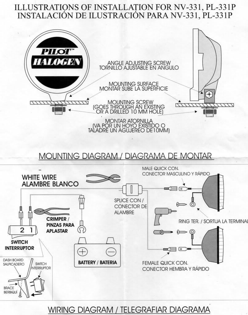
Not quite sure how to do this, so a little help please. As you can see in the dirgram, there are 2 wires comming out from the back of the lights. One of the wires show a ring around it. I'm thinking this is the groung, Is this correct? Also I think I can hook them up to any ground. Am I correct in thinking this? As you can see, it is showing a wire going to the (+) on the battery, but nothing to the (-) side, do I need to do this? Also, can the 2 grounds comming from the lights be connected together, or do I need to serprate them? Any help would be great.
Apr 12, 2007 | 11:56 AM
#2
Registered User
Joined: May 2003
Posts: 479
Likes: 0
From: Green Mountain, Colorado
Yes, the ring is on the ground wire. You just need to run this to a spot on the frame or body. Metal. Sand the paint off if necessary, drill and use a self-tapping screw and a ideally a star washer. Or use an existing bolt somewhere. They can be run to the same spot and held down by the same screw/bolt.
Last edited by GV27; Apr 12, 2007 at 12:00 PM.
Apr 12, 2007 | 11:58 AM
#3
Registered User
Joined: Apr 2007
Posts: 215
Likes: 0
From: Land of Enchantment
The wire with a ring connector on it should go to ground. It is usually black.
Any clean frame spot on the car is ground. All the frame, solid black wires, and negative battery terminal is connected. Any will work. As long as they bolt to the frame.
Any clean frame spot on the car is ground. All the frame, solid black wires, and negative battery terminal is connected. Any will work. As long as they bolt to the frame.
Apr 12, 2007 | 11:59 AM
#4
Thread Starter
Registered User
Joined: Aug 2006
Posts: 1,424
Likes: 1
From: Bay Shore, NY
Apr 12, 2007 | 12:05 PM
#5
Registered User
Joined: May 2003
Posts: 479
Likes: 0
From: Green Mountain, Colorado
BTW, that's kind of a sketchy wiring setup - you should put a fuse between the battery and the switch - as close to the battery as possible. Don't want to burn your truck down, ya know!
yes - you can hook the grounds to the same screw.
yes - you can hook the grounds to the same screw.
Apr 12, 2007 | 12:23 PM
#7
Registered User
Joined: Jan 2007
Posts: 614
Likes: 0
From: Middleburg, FL
I'd recommend a 'lighted' switch. That one has no provisions for a light. It helps you know if your lights are on during the day.
Get one with three posts on the back. The extra post is for a wire to ground. They're cheap, and if you're going through the trouble, might as well..
Get one with three posts on the back. The extra post is for a wire to ground. They're cheap, and if you're going through the trouble, might as well..
Trending Topics
Apr 12, 2007 | 12:24 PM
#8
Registered User
Joined: Jan 2007
Posts: 614
Likes: 0
From: Middleburg, FL
Correct, The negative post is connected to chassis, and anything connected to the chassis that's metal. You can use bumper mounting points to hook the ground loops to.
Last edited by UncleBob; Apr 12, 2007 at 12:25 PM.
Apr 12, 2007 | 12:28 PM
#9
Thread Starter
Registered User
Joined: Aug 2006
Posts: 1,424
Likes: 1
From: Bay Shore, NY
OK that sounds good. They are going on my brush gard, so I guess I can hook up the ground to the brush gard right, as this is hooked to my chassis.
Apr 12, 2007 | 12:54 PM
#10
Registered User
Joined: Mar 2004
Posts: 2,171
Likes: 1
From: Vancouver
there is an inline fuse in the schematic between the battery and switch,,the weird looking rectangle+cone dealie. what is the output of the lights? you dont see to many kits without a relay
Apr 12, 2007 | 01:42 PM
#11
Registered User
Joined: Oct 2005
Posts: 282
Likes: 0
From: Rochester, NH
I use a napa relay 192D and the plug for it. (I can't remember the pt. # off hand) But they can look it up np. I also use 10ga wire for all of it except from the relay to the switch.
Here is how they are wired.
Relay is from NAPA part number 192D
Terminal #30 goes to fuse and then the pos terminal of the battery.
Terminal #85 goes to the neg terminal of the battery.
Terminal #87 goes to your light.
Terminal #87a doesn't get anything unless you are drawing less tan 30 amps.
Terminal #86 goes to your switch.
To me it's worth the extra for the relays and wire.
Good luck
Apr 12, 2007 | 01:49 PM
#12
Registered User
Joined: Apr 2007
Posts: 215
Likes: 0
From: Land of Enchantment
I was thinking the same about not seeing a relay in there. Worth the time and a few extra $ to do it right. Wired that way whatever amps those lights draw is running thru that switch too. I have 100w aircraft lights on my 4runner (4 front and 4 rear). they are run thru relays for each pair. The only thing the switch does is power the relay, all of aprox. 3amp draw on the switch.
I use a napa relay 192D and the plug for it. (I can't remember the pt. # off hand) But they can look it up np. I also use 10ga wire for all of it except from the relay to the switch.
Here is how they are wired.
Relay is from NAPA part number 192D
Terminal #30 goes to fuse and then the pos terminal of the battery.
Terminal #85 goes to the neg terminal of the battery.
Terminal #87 goes to your light.
Terminal #87a doesn't get anything unless you are drawing less tan 30 amps.
Terminal #86 goes to your switch.
To me it's worth the extra for the relays and wire.
Good luck
and yes i would use a relay, and not the direct switch to the battery, because then it is possible 1) to melt the switch and 2) leave your lights on with the ignition off.
Apr 12, 2007 | 01:51 PM
#13
Contributing Member
Joined: Dec 2005
Posts: 2,226
Likes: 0
From: Houston (home), Atlanta (school), Cincinnati (work)
yeah thats the simplest wiring of lights. it will work just fine assuming the switch can handle all that current draw. that would be my concern but if it came with the lights, it should be ok. a relay would be the safest however
Apr 12, 2007 | 02:02 PM
#14
Registered User
Joined: Jun 2006
Posts: 66
Likes: 0
From: NWO, Canada
For Current Draw
Power(watts) = Voltage X Current(Amps)
12V/Power(Watts) = Current(Amps)
Last edited by rhah; Apr 12, 2007 at 02:04 PM.
Apr 12, 2007 | 02:10 PM
#15
Registered User
Joined: Oct 2005
Posts: 282
Likes: 0
From: Rochester, NH
# 87a Has NOTHING to it on mine.
I got those instruction along time ago from somehwere and thats how my lights have been wired for several years now. Still the same switches and relays that I started with.
I just tape up the #87A wire and forget about it
I got those instruction along time ago from somehwere and thats how my lights have been wired for several years now. Still the same switches and relays that I started with.
I just tape up the #87A wire and forget about it
Apr 12, 2007 | 06:01 PM
#16
Contributing Member
Joined: Jul 2005
Posts: 12,261
Likes: 7
From: Siletz,Oregon
i would go buy a roll of 16ga wire and some connectors a relay and a switch
http://www.ultimateyota.com/index.ph...26&topic=387.0
http://www.ultimateyota.com/index.ph...26&topic=387.0
Apr 13, 2007 | 11:33 AM
#17
Thread Starter
Registered User
Joined: Aug 2006
Posts: 1,424
Likes: 1
From: Bay Shore, NY
i would go buy a roll of 16ga wire and some connectors a relay and a switch
http://www.ultimateyota.com/index.ph...26&topic=387.0
http://www.ultimateyota.com/index.ph...26&topic=387.0
Apr 13, 2007 | 11:58 AM
#18
Registered User
Joined: Jan 2007
Posts: 614
Likes: 0
From: Middleburg, FL
Relay not necessary. It will work.
However, hooking the switch up to 'The Clapper' would be cool. That way, when you're in the woods, you can "CLAP-ON" your lights to locate your truck in the dark.
However, hooking the switch up to 'The Clapper' would be cool. That way, when you're in the woods, you can "CLAP-ON" your lights to locate your truck in the dark.
Apr 13, 2007 | 12:38 PM
#19
Thread Starter
Registered User
Joined: Aug 2006
Posts: 1,424
Likes: 1
From: Bay Shore, NY
Apr 13, 2007 | 01:21 PM
#20
Contributing Member
Joined: Jul 2005
Posts: 12,261
Likes: 7
From: Siletz,Oregon

Thread
Thread Starter
Forum
Replies
Last Post
Steven.m.paulk
86-95 Trucks & 4Runners
4
Jun 7, 2020 10:45 AM
smilen724
86-95 Trucks & 4Runners (Build-Up Section)
13
Nov 8, 2015 04:11 PM
Brodetski
86-95 Trucks & 4Runners (Build-Up Section)
0
Sep 30, 2015 11:50 PM


