
Gm alt conversion not charging.. Any info is appreciated!
 Sep 1, 2016 | 02:57 PM
#21

Thread Starter
Registered User
Joined: Nov 2015
Posts: 33
Likes: 0
The original link I followed for this conversion said he used a 175 amp fusible link for his power wire directly to the battery. I was planning on the same thing since I used a 4 gauge wire as well.
I also planned to remove the stock wire all the way from the fuse box to the link where the wire goes to the alternator. I still need to switch my resistor as you guys mentioned before. I planned to clean up all the extra wiring I have after de sniffing my motor to clean up my engine bay. I need to order that fusible link asap. So by doing that I will actually be using the full amps my alternator is capable of putting out correct? As well as eliminating a dangerous situation as you guys mentioned as well.
I also planned to remove the stock wire all the way from the fuse box to the link where the wire goes to the alternator. I still need to switch my resistor as you guys mentioned before. I planned to clean up all the extra wiring I have after de sniffing my motor to clean up my engine bay. I need to order that fusible link asap. So by doing that I will actually be using the full amps my alternator is capable of putting out correct? As well as eliminating a dangerous situation as you guys mentioned as well.
Sep 1, 2016 | 03:18 PM
#22
Registered User


Joined: Mar 2012
Posts: 7,125
Likes: 681
zpayne,
Pls make sure the 175-Amp FL is suited to protect your new B wire.
Yes, removing the stock wire all the way to fuse block would clean up things, and while you're at it, add extra protection like a flexible conduit for B wire.
Yes, IF you take power (fused) directly from battery positive, you can use your full capacity of your alternator; battery and alt now basically directly working together.
Some worst-case-scenarios (I discussed on my thread):
1) IF battery internally fails or connection between battery connector and post fails while you're winching with engine on, alt may try to supply all required power to winch. IF that power exceeds rating of new FL, FL will melt, but your stock fuse block and stock circuits will not be affected.
2) IF alternator fails under same conditions, battery will still supply all it can. Current will not pass your stock fuses, so again, your stock circuit will be left unharmed.
Either way, it would much easier and less expensive to repair than IF your stock fuse network were affected.
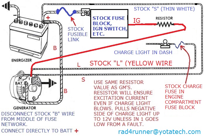
BTW, I found my notes on GM-alt schematic... This is exactly how you would wire your resistor...
Pls make sure the 175-Amp FL is suited to protect your new B wire.
Yes, removing the stock wire all the way to fuse block would clean up things, and while you're at it, add extra protection like a flexible conduit for B wire.
Yes, IF you take power (fused) directly from battery positive, you can use your full capacity of your alternator; battery and alt now basically directly working together.
Some worst-case-scenarios (I discussed on my thread):
1) IF battery internally fails or connection between battery connector and post fails while you're winching with engine on, alt may try to supply all required power to winch. IF that power exceeds rating of new FL, FL will melt, but your stock fuse block and stock circuits will not be affected.
2) IF alternator fails under same conditions, battery will still supply all it can. Current will not pass your stock fuses, so again, your stock circuit will be left unharmed.
Either way, it would much easier and less expensive to repair than IF your stock fuse network were affected.
BTW, I found my notes on GM-alt schematic... This is exactly how you would wire your resistor...
Sep 1, 2016 | 03:58 PM
#23
Thread Starter
Registered User
Joined: Nov 2015
Posts: 33
Likes: 0
zpayne,
Pls make sure the 175-Amp FL is suited to protect your new B wire.
Yes, removing the stock wire all the way to fuse block would clean up things, and while you're at it, add extra protection like a flexible conduit for B wire.
Yes, IF you take power (fused) directly from battery positive, you can use your full capacity of your alternator; battery and alt now basically directly working together.
Some worst-case-scenarios (I discussed on my thread):
1) IF battery internally fails or connection between battery connector and post fails while you're winching with engine on, alt may try to supply all required power to winch. IF that power exceeds rating of new FL, FL will melt, but your stock fuse block and stock circuits will not be affected.
2) IF alternator fails under same conditions, battery will still supply all it can. Current will not pass your stock fuses, so again, your stock circuit will be left unharmed.
Either way, it would much easier and less expensive to repair than IF your stock fuse network were affected.
BTW, I found my notes on GM-alt schematic... This is exactly how you would wire your resistor...
Thanks for all the help RAD!!! I can't believe how many write ups on this that are directly Toyota related with all wrong info as to how to splice that resistor in. So I hope when people search this topic they come across this thread and it will be a one time reading and they will have all the info they need and more because so many people have chimed into this thread! thanks again guys!
Sep 1, 2016 | 04:39 PM
#24

Registered User

Joined: Sep 2007
Posts: 8,381
Likes: 873
From: San Francisco East Bay
I don't think it's a good idea to run the "B" wire straight to the battery post.
Here's the charging circuit for a '94. I think the '87 would be pretty much the same, but because this is the EWD I have, this is how I'll try to explain it.
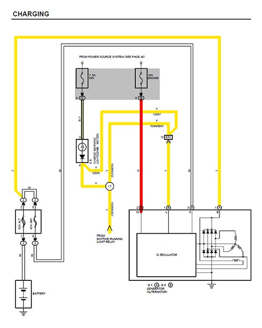
The "big fat yellow" wire ("B") goes to the fuse block, and then gets to the battery through the 80amp "alt" fuse. If the alternator shorted internally (or you just slipped with a wrench, running or not), that fuse will prevent the battery from trying to put several hundred amps into a dead short. But what about my 140 amp alternator? You're never going to use more than 30 amps or so to charge the battery, and if you try to pull more than 80 amps from the battery (for longer than it would take to turn over the starter on a cold morning) you want the fuse to blow to protect the battery (and everything else).
All of your new loads (winch?) connect at a fuse block, either the existing one or a new one. The alternator output goes to the fuse block, not directly to the battery. The battery powers the fuse block with engine off, but with the alternator running (putting out about 14.1v) the current flows BACK through that 80amp fuse to charge the battery.
What if I'm pulling 120amps to my new winch, stereo, seat heaters, etc., and then switch off the engine? The 80amp fuse blows. If you hooked all 120amps of load right up to the battery (alone), the battery would melt and catch fire in only about a minute. Well, maybe, maybe not, but it would destroy the battery.
You mentioned a fusible link in the B line to the battery; that would serve sorta the same purpose as the factory 80amp alt fuse. But fusible links are a "last line of defense"; they're not tested to open at any particular current other than "a whole lot." Also, if you're following Rad4Runner's diagram, you have to build a whole new fuse block with a 140amp fuse just to get the power from the battery post to the new block. So I'd recommend following the Toyota method: isolate the battery behind a (big) 80amp fuse. Distribute your 140 amps from the new alternator up close to the new loads in the fuse block.
Here's the charging circuit for a '94. I think the '87 would be pretty much the same, but because this is the EWD I have, this is how I'll try to explain it.
The "big fat yellow" wire ("B") goes to the fuse block, and then gets to the battery through the 80amp "alt" fuse. If the alternator shorted internally (or you just slipped with a wrench, running or not), that fuse will prevent the battery from trying to put several hundred amps into a dead short. But what about my 140 amp alternator? You're never going to use more than 30 amps or so to charge the battery, and if you try to pull more than 80 amps from the battery (for longer than it would take to turn over the starter on a cold morning) you want the fuse to blow to protect the battery (and everything else).
All of your new loads (winch?) connect at a fuse block, either the existing one or a new one. The alternator output goes to the fuse block, not directly to the battery. The battery powers the fuse block with engine off, but with the alternator running (putting out about 14.1v) the current flows BACK through that 80amp fuse to charge the battery.
What if I'm pulling 120amps to my new winch, stereo, seat heaters, etc., and then switch off the engine? The 80amp fuse blows. If you hooked all 120amps of load right up to the battery (alone), the battery would melt and catch fire in only about a minute. Well, maybe, maybe not, but it would destroy the battery.
You mentioned a fusible link in the B line to the battery; that would serve sorta the same purpose as the factory 80amp alt fuse. But fusible links are a "last line of defense"; they're not tested to open at any particular current other than "a whole lot." Also, if you're following Rad4Runner's diagram, you have to build a whole new fuse block with a 140amp fuse just to get the power from the battery post to the new block. So I'd recommend following the Toyota method: isolate the battery behind a (big) 80amp fuse. Distribute your 140 amps from the new alternator up close to the new loads in the fuse block.
Last edited by scope103; Sep 1, 2016 at 04:46 PM.
Sep 1, 2016 | 06:31 PM
#25

Registered User
Joined: Jun 2011
Posts: 1,699
Likes: 75
some types of agm/gel batteries don't have any maximum charge current limitation, the rapid recharge rate is limited only by the temp of the battery, 125 degrees: https://www.optimabatteries.com/en-u.../charging-tips
"All ODYSSEY batteries can be quickly charged. The graph below shows their exceptional fast charge characteristics at a constant 14.7V for three levels of inrush current. These current levels are similar to the output currents of modern automotive alternators. Table 6 and Figure 7 show the capacity returned as a function of the magnitude of the inrush3 current. Standard internal combustion engine alternators with an output voltage of 14.2V can also charge these batteries. The inrush current does not need to be limited under constant voltage charge." http://www.odysseybattery.com/docume...1_0411_000.pdf
it sounds optimistic, and it's certainly better than a standard lead-acid battery, but i don't see any of it being a guarantee that an agm battery will survive a 160 amp burst charge attempt :-0
at any rate, the wire that shipped with my 160 amp alternator is too small to handle 160 amps, i think that it'll melt well before that, but it's not safe like a fuse.
"The charge current
A rule of thumb for gel and AGM batteries states that the minimum charge current should be 15 to 25% of the battery capacity. Connected equipment usually also needs to be powered during charging, so include the power used for that purpose in the abovementioned figure. This means that, with a battery set of 400 Ah and a connected load of 10 amps, battery charger capacity has to be between 70 and 90 amps in order to charge the battery in reasonable time.
The maximum charge current is 50% for a gel battery and 30% for an AGM battery. For a Lithium Ion battery the charge current can be the same as the capacity. A 180 Ah Lithium Ion battery, for example, can be recharged with 180 amps.
The charge system
Ensuring the longest possible lifespan for gel, AGM and Lithium Ion batteries requires a modern battery charger with 3-step+ charging and a sensor for measuring battery temperature. These battery chargers will constantly regulate charge voltage and charge current and adapt the charge voltage to the battery temperature." http://www.mastervolt.com/news/charging-batteries/
my old diehard platinum is rated at ~58ah, and i think that it's agm, so if that general rule applies it's limited to ~18 amps max charge current for best life span.

Thread
Thread Starter
Forum
Replies
Last Post
Camorunner
86-95 Trucks & 4Runners
2
Feb 14, 2016 07:49 AM


