
Anybody know what this is?
 Dec 12, 2012 | 07:51 PM
#21
Thread Starter
Registered User
iTrader: (1)
Joined: Feb 2012
Posts: 654
Likes: 1
From: Earlysville, Va
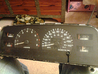
He says it's from a 95 4runner. I know the years for changes don't line up between the trucks and 4runners, but I thought parts were still interchangeable between his and mine. It should be here Saturday. We'll see how it goes.
Dec 12, 2012 | 07:56 PM
#22
Registered User
Joined: Oct 2009
Posts: 1,034
Likes: 1
From: Springfield, Orygun
The 84-88s might look different, but that looks just like the back of mine, minus the flux capacitor. 99% sure I had 4 plugs for mine. I wonder if Toyota put these in other rigs with a different tach signal, say a diesel, and that converts the signal for a coil fired engine? Who wants to tear out their diesel dash?
Sent from my LG-P505 using YotaTech
Sent from my LG-P505 using YotaTech
Dec 13, 2012 | 02:16 AM
#23
Thread Starter
Registered User
iTrader: (1)
Joined: Feb 2012
Posts: 654
Likes: 1
From: Earlysville, Va
The 84-88s might look different, but that looks just like the back of mine, minus the flux capacitor. 99% sure I had 4 plugs for mine. I wonder if Toyota put these in other rigs with a different tach signal, say a diesel, and that converts the signal for a coil fired engine? Who wants to tear out their diesel dash?
Sent from my LG-P505 using YotaTech
Sent from my LG-P505 using YotaTech
I know I'm going to have to adjust the tach and possibly run a write from the coil for it but I hope it's a bolt in project. I want to change the odometer too so it's right for my truck.
Dec 13, 2012 | 12:45 PM
#24
Registered User
Joined: Oct 2009
Posts: 1,034
Likes: 1
From: Springfield, Orygun
Did Toyota ever put a diesel in the 95 Runner? If thats what it is then it's not original to this guys rig. This came out of one with a 3.0 V6/automatic.
I know I'm going to have to adjust the tach and possibly run a write from the coil for it but I hope it's a bolt in project. I want to change the odometer too so it's right for my truck.
Sent from my LG-P505 using YotaTech
Dec 16, 2012 | 05:59 PM
#25
Thread Starter
Registered User
iTrader: (1)
Joined: Feb 2012
Posts: 654
Likes: 1
From: Earlysville, Va
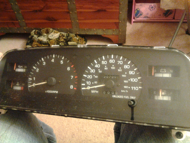
Well the new-to-me cluster came in this weekend. I checked the part number and it's definitely from a 1995 4Runner 3.0 V6/automatic setup.
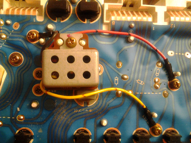
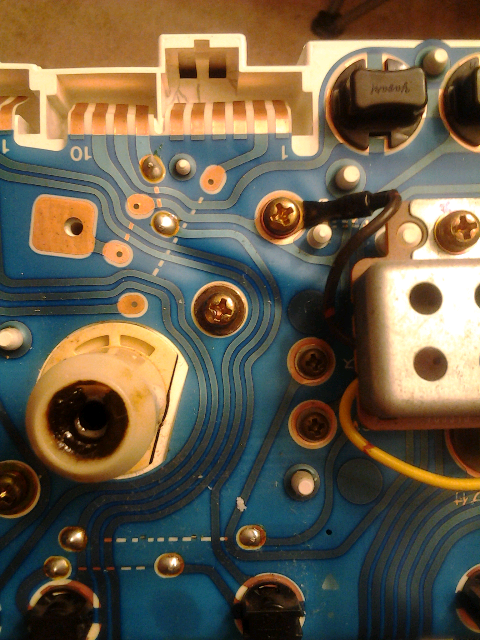
I still have no idea what this is for

Following the circuitry on the back it connects two pins from different plugs on the back. Still doesn't help me unless I know what those pins are wired to.
I still have no idea what this is for
Following the circuitry on the back it connects two pins from different plugs on the back. Still doesn't help me unless I know what those pins are wired to.
 Dec 16, 2012 | 06:15 PM
#27
Registered User
Joined: Oct 2009
Posts: 1,034
Likes: 1
From: Springfield, Orygun
I am doing the opposite, i have a regular 5spd and am putting a sr5 ECT automatic cluster in to it.
I wanted to clarify the pin outs, i found it hard to follow the 5-6 4-5. My big problem is my cluster's oil and temp dont work, (yes I have the correct sender) The temp goes to 45% and locks there no matter what, the oil does not respond, check the wire and i get a great signal. What I am asking is does anyone know what the resistance is supposed to be across the oil senders terminals, and for the temp is there a way to test that one too?
For Connector A
On the auto sr5
Connector A
Pin 1 AT Light
Pin 2 Oil sender
Pin 3 Back Door
Pin 4 Check motor light
Pin 5 Tach
Pin 6 norm led
Pin 7 temp
Pin 8 n/a
Pin 9 pwr led
Pin 10 n/a
Pin 11 n/a
Pin 12 n/a
on the 5spd (non tach on mine)
Pin 1 n/a
Pin 2 AT light
Pin 3 Oil sender
Pin 4 Back Door
Pin 5 Check motor light
Pin 6 na (tach on sr5)
Pin 7 temp
Pin 8 n/a
Pin 9 n/a
Pin 10 n/a
Pin 11 n/a
Pin 12 n/a
the connector b is the same across the board
Connector C auto
Pin 1 high beam
Pin 2 4wd
Pin 3 swb
Pin 4 swa
Pin 5 fuel-
Pin 6 fuel+
Pin 7 belts
Pin 8 resistor circut
Pin 9 chg
Pin 10 fuel light
Pin 11 ign +
Pin 12 Ground
Connector C 5spd
Pin 1 high beam
Pin 2 4wd
Pin 3 swb
Pin 4 Fuel-
Pin 5 fuel+
Pin 6 na
Pin 7 belts
Pin 8 resistor circut
Pin 9 chg
Pin 10 fuel light
Pin 11 ign +
Pin 12 Ground
Sent from my LG-P505 using YotaTech

 Dec 16, 2012 | 06:50 PM
#30
Registered User
Joined: Oct 2009
Posts: 1,034
Likes: 1
From: Springfield, Orygun
Well...I didn't mean to insinuate you had to switch wires anywhere. But thought it would help explain what that flux capacitor is for. They should plug right in and work.
Sent from my LG-P505 using YotaTech
Sent from my LG-P505 using YotaTech
Dec 16, 2012 | 07:05 PM
#33

Registered User
Joined: Jun 2011
Posts: 179
Likes: 0
From: Twin Cities, MN
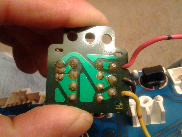
SPARKS89, could you please take a nice picture of the left side of the back of the meter? I need to see where the black wires trace runs.
This doesn't seem to have anything to do with the fuel gauge. The red or orange wire actually goes to the brake warning light and the yellow goes to the highbeam indicator light. Just need to nail down the black wire, which very likely goes to pin 9 on the C connector, which is ground. Just want to verify...
This doesn't seem to have anything to do with the fuel gauge. The red or orange wire actually goes to the brake warning light and the yellow goes to the highbeam indicator light. Just need to nail down the black wire, which very likely goes to pin 9 on the C connector, which is ground. Just want to verify...
 Dec 16, 2012 | 07:15 PM
#37
Registered User
Joined: Jan 2011
Posts: 1,746
Likes: 6
From: 46 50' 36.82'' N 122 19' 41.01'' W
You thinking it's to eliminate dimly lit brake/hi beam lights when they're off?
Dec 16, 2012 | 07:23 PM
#38
Registered User
Joined: Jan 2011
Posts: 1,746
Likes: 6
From: 46 50' 36.82'' N 122 19' 41.01'' W
Best guess I got given the wiring.
Well something to do with an override on the brake light for low fluid warning, and possibly a fog light shutoff for when the high beams are on.
Other then that no idea
Well something to do with an override on the brake light for low fluid warning, and possibly a fog light shutoff for when the high beams are on.
Other then that no idea
Dec 16, 2012 | 07:26 PM
#39
Thread Starter
Registered User
iTrader: (1)
Joined: Feb 2012
Posts: 654
Likes: 1
From: Earlysville, Va
I want to put it in my 89 pickup with a 22re. I know I'll have to adjust the tach and I already have another sending unit for the oil pressure on the way. I may have to run a tach wire as well which I want to put into the plug if I have to do it. I've already been working on adjusting the odometer to match what the truck actually has. It's easy but TIME CONSUMING adjusting it 21,000 by hand! My only concern is the plug configuration.
Dec 16, 2012 | 07:32 PM
#40
Registered User
Joined: Jun 2011
Posts: 179
Likes: 0
From: Twin Cities, MN
Ok, so what that little box does is it turns on your brake warning light (parking and low fluid) when your highbeams are on.
Now that makes absolutely no sense at all, so what I'm guessing is that they screwed up the combo meter and this bandaids it given that the harnesses are still correct. Without having a meter and being able to do a bunch of tracing on the actual unit, I can't tell you what is actually wrong. But if you disconnect those wires and try to make it work, I really doubt it'll work quite right.
There's one particular spot right by where the red or orange wire is screwed in. There are some diodes there that act with the bulb check relay to essentially turn on your ATF temp warning and brake warning lights while you're cranking. That's where I bet they messed up.
I really want to do a cluster swap now just so I have an excuse to buy and reverse engineer one of these even more!


