When you click on links to various merchants on this site and make a purchase, this can result in this site earning a commission. Affiliate programs and affiliations include, but are not limited to, the eBay Partner Network.
The other day, I picked up a 100 amp alternator that came from a 92 Toyota MR -2. I want to use it to replace the factory alternator in my 1989 4 runner which is rated at 60 amps. It looks like the main power wire, for the charging circuit goes through a 80 amp fusible link just before it connects to the battery. I'm thinking I should probably use a heavier wire and upgrade the fusible link Anybody have any recommendations for wire gauge and fuse rating?
Last edited by wrenchtech; Nov 27, 2016 at 06:23 PM.
After a little research, I'm thinking 4 gauge wire, (possibly 2 gauge) and a 120 amp fusible link. So now I will ask, does anybody know if Toyota makes a 120 amp fusible link that will fit my fuse box? And am I putting anything else at risk by increasing the fuse rating?
Do NOT upgrade the Fusible link. It is there to protect stock circuit.
If you want:
1) Connect your 120-amp FL as close as possible to the battery,
2) Connect your added 4AWG wire to that,
3) Use that to supply a fuse distribution block for ALL circuits added to stock.
This way, if anything happens to non-stock circuits only fuses supplying those will blow. Stock FL, fuses and wiring will remain functional and truck will still work.
Last edited by RAD4Runner; Nov 27, 2016 at 11:55 PM.
I have the Toyota factory wiring manual for my 4runner. And I have been inside that fuse box before, but I think I'm going to have to look at it again closely before I make any decisions. I also know a guy who rebuilds alternators who should have some expert advice. I'll report back here when I get it sorted out.
You're getting good advice. Just one principle I'll add, that is implied in that advice but not specifically stated. The fusing is there to protect the downstream wiring, not the upstream power source.
Example: Your house. The power company could easily supply 1000 amps to your service box in your garage. That doesn't mean you want your main breaker to be 1000 amps. It's 100/200 amps to protect the service box, and the individual 15/20 amp breakers protect the 14/12 gauge wiring in the walls.
So, you want to leave that 80 amp fusible link in place to protect the stock harness.
Excellent description. I've often seen an otherwise competent handyman wire in a light fixture by extending a circuit (protected by a 20amp breaker) with 14ga wire. Why? Because the light fixture is never going to draw in excess of 15 amps, and 14ga is okay for 15amps.
It is possible to do upgrades to the electrical system, but you want to be careful and use a safe design. You don't want to burn your truck to the ground. Before I'd even consider buying a more powerful alternator, I'd upgrade my wiring. Upgrading your wiring can improve the performance of your electrical system without adding a larger alternator. If you are trying to add accessories, you need to take your potential additional power demand in to consideration when you are upgrading your wiring. My approach was to upgrade the main cables and build a distribution center so that I could add more fuse boxes and also power a medium load accessory like an electric cooling fan or a small power inverter. I don't want to add any accessories that go thru the factory fuse box. If anything, I want to reduce the load on the factory box because it is old and the factory wires are old. I'm planning on adding a headlight harness in the future and powering it with my new fuse box. As mentioned by RJR, when you are fusing things, you need to match the size of the fuse to what is downstream. So I've built my power distribution center attached to the side of my battery box and I've included an ANL fuse holder that I can use to attach a 4 gauge cable to, so if I add a larger alternator in the future I'll be ready. My output branches from my power distribution hub are fused with midi fuse blocks. You can buy an inline maxi fuse holder with an 8 gauge wire. This came in handy to use as an output for a midi fuse holder as the midi fuses go down to 40 amps and bolt in place, while you can buy a maxi fuse as small as 30 amps and it plugs in to the holder making it easier to change ( This is how I routed power to a small fuse box ). My factory fuse box receives power from a branch cable on a factory GM cable for a Saturn car ( the Saturn car has a much larger alternator and power demand than my truck with a 40 amp factory alternator ). The larger branch of the Saturn cable, which would normally go to the starter on a Saturn, goes to the power distribution hub.
Last edited by chuckross1957; Nov 28, 2016 at 12:07 PM.
Thanks for this thread.
When I upgraded the Alt, I ran a "welding" cable (1/0?) from the alt to the battery (thats right - no fuse).
I left the rest of the OEM harness in place.
I shrink wrapped the ring end that used to go to the back of the alternator.
I know that the charge wire is tied to the battery.
I didn't want to cut if off, in case I had to go back to stock.
I probably want to insert a useable link in that line, near the battery to protect that cable if it shorts agains the body for some reason...
The master has already responded (Rad4Runner) but I thought I would drop a link by from my thread where I was doing this exact same thing. I upgraded my 88's alternator and Rad helped me through the wiring. There are some pics and stuff that may be useful
Generally speaking, piggy backing is considered an acceptable method. I haven't done this with a (my) Toyota, but it is my intention to do so in the future. By piggy backing, I mean leaving the original cable going out of the alternator connected and adding an additional larger cable going to the positive terminal on the battery. Also the big three upgrade is recommended when adding a larger alternator, in particular increasing and improving the ground wires. https://alternatorparts.com/do-i-nee...tery-wire.html
Last edited by chuckross1957; Dec 1, 2016 at 10:57 PM.
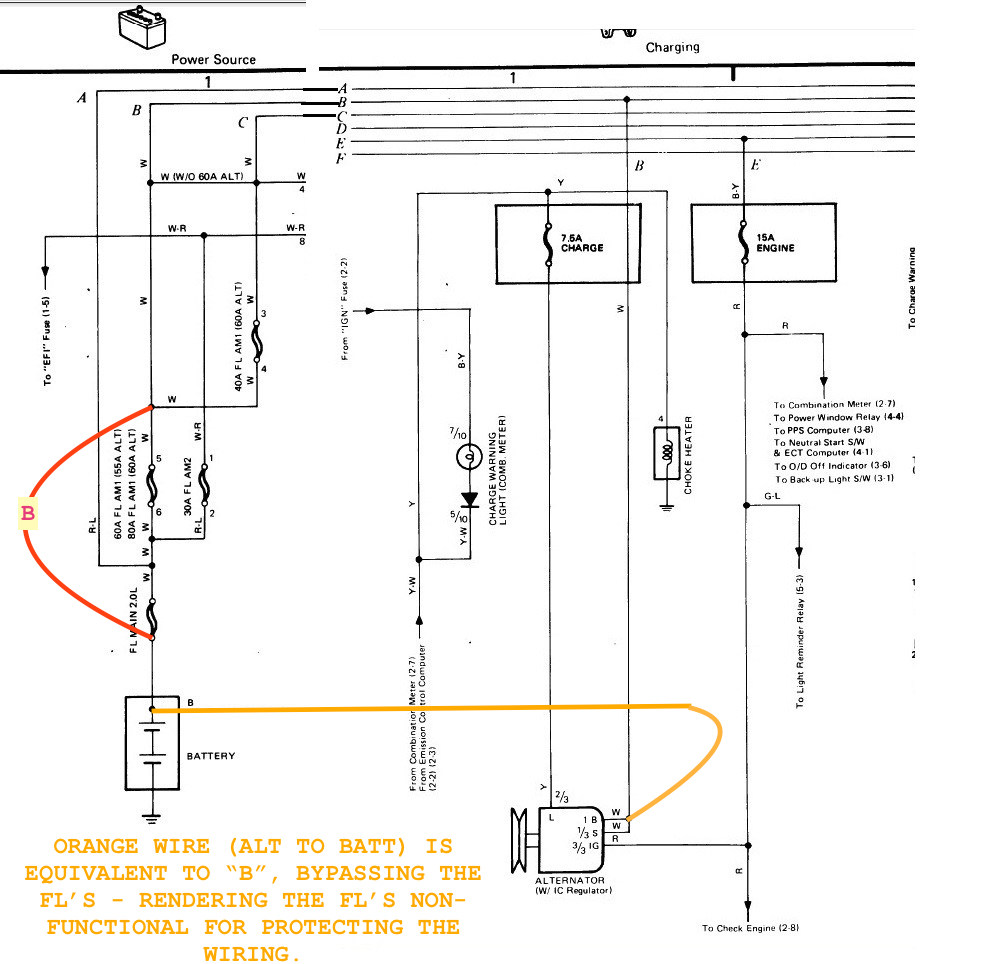
By "adding an additional larger cable going to the positive terminal on the battery", do you mean a larger cable from the screw terminal on alternator to the positive battery terminal (orange in schematic below)? If yes, that will produce an unsafe condition.
If you trace the "B" wire run on the schematic below, you will see that the "larger wire" is equivalent to shorting the supply and load side of your Fusible Links (red "B").
RAD, After taking a closer look at the original wiring diagram you posted, I think I could use a 40 amp fuse on the original output cable. The fuse should address the issue that you pointed out. I was planning to replace the short section of cable that attaches to the alternator with a 2 awg cable and connect the original cable and a 4 awg to the terminal on the driver's side fender well. Now, I'll put a fuse in line with the terminal out to the original cable that goes to the fuse box. I'll take a closer look at the size of the original cable, I think the cable is large enough to carry over 40 amps safely. I also plan on replacing the original terminal with an upgraded one. I think I can safely use an 80 amp ANL fuse on the 4 awg cable. Thanks for pointing this out!
Last edited by chuckross1957; Dec 3, 2016 at 08:56 AM.
RAD, After taking a closer look at the original wiring diagram you posted, I think I could use a 40 amp fuse on the original output cable.......
Sorry, hard to visualize (I'm a visual guy) A sketch might help clarify.
Whatever you do, I would not recommend putting fuses in parallel. Parallel WIRES are good for increasing current carrying capacity but parallel FUSES may produce unpredictable results in case of a short/overload and complicate troubleshooting.
it looks like the red "check engine" wire in rads diagram is not used... offhand i can't recall what that does.
If you're referring to the red "IG" wire, it's to excite the alternator winding to start generating voltage. Correct, it's not used in the Powermaster / GM systems.
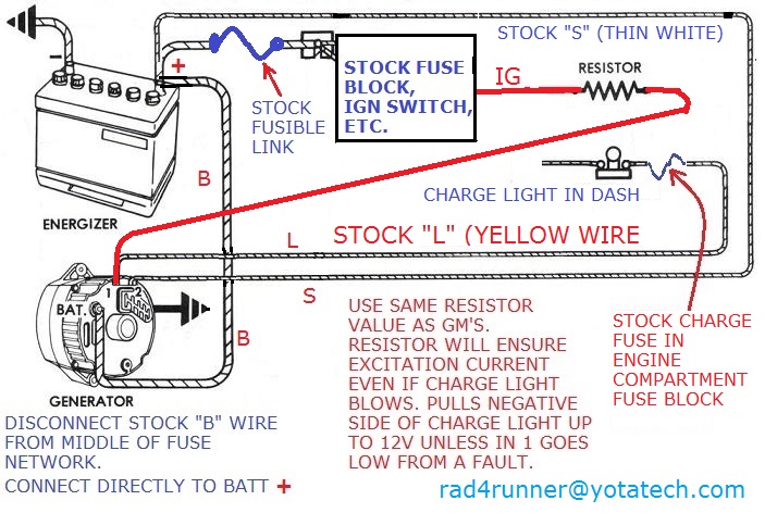
On the GM one-wire and Powermaster system, current through the the L (charge fault) circuit provides that excitation. However, there is a weak point in that system: IF the charge light bulb gets busted, you also lose excitation and alternator will stop working. A work around (IIRC, used in some Buick's) is a resistor in parallel with the Charge fault light bulb, like this:
Can be modified by taking power from the "IG" wire like this:
Excellent article by Al Dolney, Thanks for posting it osv. I like the wiring diagrams comparing the original alternator wiring method to an upgraded method of wiring the alternator. One of my concerns about RAD's method is the amount of current flow going thru the wimpy original fusible link, the one that goes from the battery terminal to the fuse box. By eliminating the original pathway out of the alternator, you could be forcing more current thru the fusible link, for a longer amount of time, than it is intended to handle. I can't be certain with Al's diagrams, because they are simplified, but it it looks like he eliminated that fusible link. But if you eliminate this fusible link, it appears the "A" wire will not be protected. It looks like the "A" wire should have its' own fuse. A couple of other things, It seems the alternator on my 86 is a 60 amp, not a 40 amp. I don't how I got off track with 40 amps since I changed it out myself several years ago. Also, there seems to be some agreement that disconnecting the original "B" cable at the alternator is the way to go. There may some differences between the 22re and the 22r or model years which could explain the differences between RAD and Al's wiring diagrams in the area of the fuse box.
i think that rad's first diagram is for a toyota type of alternator? the wiring is different.
i had to dig for the al dolney document, the original url went dead years ago... it appears that the factory 8 gauge wire is cut, which matches what rad posted??(thx rad!), so there isn't any parallel bypass connection problem.
it does look like al put in a new 6 gauge wire, going into the 80amp fuse, but he doesn't show the 30amp fuse, it's a bit confusing.
i think that rad's first diagram is for a toyota type of alternator? the wiring is different.
Yes, that's 1986-1988 22RE charging circuit.
And, OSV, pls research the resistor value I saw it on the web somewhere.
Originally Posted by chuckross1957
...By eliminating the original pathway out of the alternator, you could be forcing more current thru the fusible link...ut myself several years ago.
The fusible link is designed to handle all the current the stock circuit requires. I wired my upgrade so all additional/after-factory systems will take fused power directly from the battery. No matter what happens to after-factory circuit, they will not affect the stock fusible link and the stock circuit.
Also, there seems to be some agreement that disconnecting the original "B" cable at the alternator is the way to go.
There should be because like I mentioned above adding an "upgrade" cable between alt "B" post and battery pos post while leaving stock "B" wire between alt "B" post and batt positive will negate presence of the fusible links.
Last edited by RAD4Runner; Dec 4, 2016 at 06:31 PM.
Thanks RAD for posting the factory wiring diagram and your observations about the details of upgrading the wiring to match a larger alternator. This has been an interesting thread with some great ideas. I am including a link with some info about automotive wiring, in particular discussing the importance of a good alternator ground. http://www.dragzine.com/tech-stories...rancis-wiring/
Thanks RAD for posting the factory wiring diagram and your observations about the details of upgrading the wiring to match a larger alternator. This has been an interesting thread with some great ideas. I am including a link with some info about automotive wiring, in particular discussing the importance of a good alternator ground. http://www.dragzine.com/tech-stories...rancis-wiring/
dang, that fusible link burning up is a bit unnerving! lol
i found an alternator thread here on the forum, from a couple of years ago, a couple of people are running 50-ohm resistors... i gotta do that, my charge light hasn't burnt out yet, but i don't want to be stranded.

 Nov 27, 2016 | 06:09 PM