
$3 Noid Light for 22re
 Jul 11, 2013 | 11:50 AM
#1
Thread Starter
Super Moderator
iTrader: (1)
Joined: Aug 2008
Posts: 11,787
Likes: 28
From: Anderson Missouri
$3 Noid Light for 22re
After suspecting my Injectors not firing. I tried to find a noid light for Toyotas. My local parts store didnt sell or rent a tester. I hear some do but not in my area from my experience. This worked for me and I seen a question recently about someone else asking. Hope this works for them as well.
I disconnected my fuel pump at its electric connection by the fuel tank. I was also checking for fuel flow problems and didnt want fuel everywhere, if fuel lines are connected, you wouldnt need to do this step. I then stuck each lead into the injector connection and while cranking the motor was able to observe the LED flashing.
Edited: Scope103 has a great point in the post below. The LEDs are polarized. If it doesnt work one way, switch the polarity or the leads the oppisite way around. Thanks for Catching that Scope 103.
On post #22 jbtvt shows that you will need your ground hooked up.
My $3 noid light. I wasnt able to find one anywhere and this worked great. It flickered each time I cranked it. I just couldnt get any pictures of it lighted.
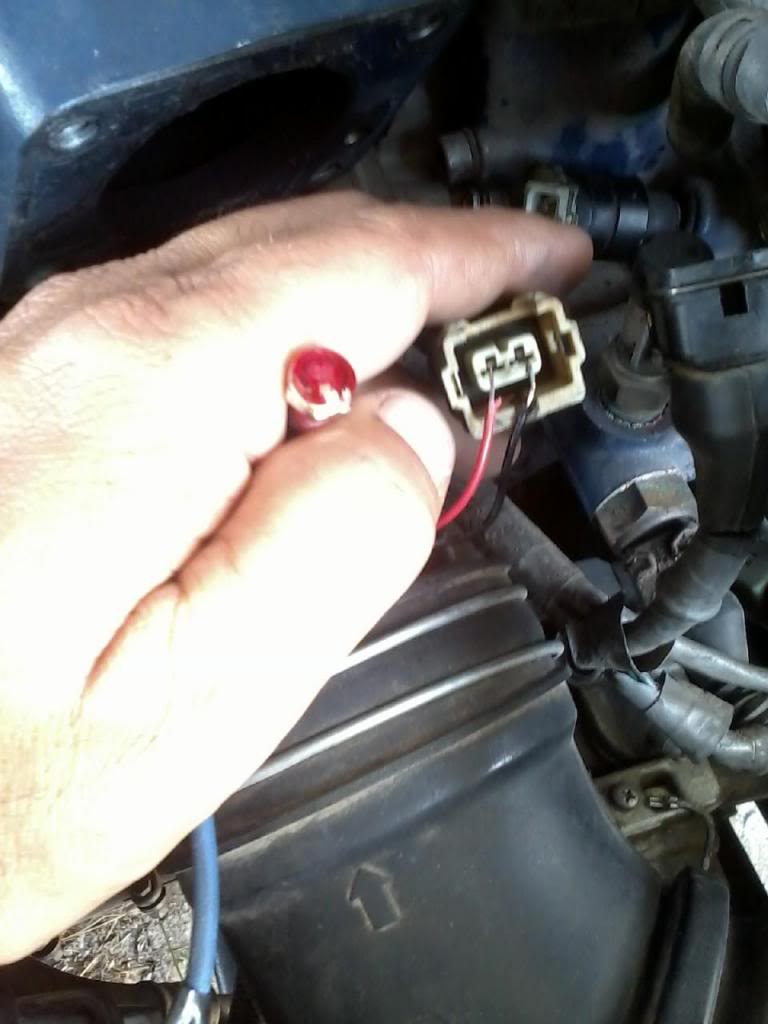
I used the 12 Volt red one. Radio Shack Part Number #276-0270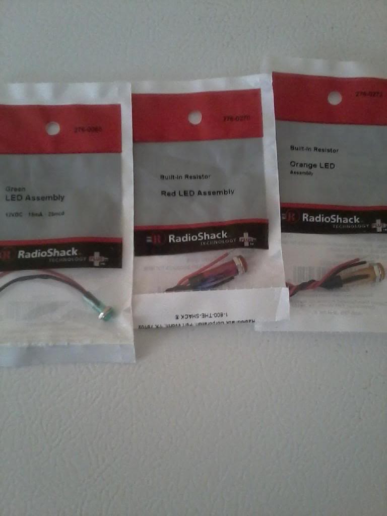

Last edited by Terrys87; Aug 4, 2016 at 03:47 AM.
Jul 12, 2013 | 05:22 PM
#4

Registered User

Joined: Sep 2007
Posts: 8,384
Likes: 875
From: San Francisco East Bay
Note that LEDs are polarized; you should only be able to get the flash with it plugged in the right way. Of course, if it doesn't work, there is only one "other" way. Once you figure it out, don't forget it, as you'll need that orientation for each other injector.
Jul 14, 2013 | 03:57 PM
#5
Thread Starter
Super Moderator
iTrader: (1)
Joined: Aug 2008
Posts: 11,787
Likes: 28
From: Anderson Missouri
Thanks scope103!!! I missed posting that. ^^^ Two sets of eyes are better then one. Glad you mentioned that.
I have seen several post from you on the 3.0 and you have a great understanding of the 3.0. I am sure this would work on any other motor as well, but since I havent done it on one of those, I just mentioned the 22re.
LEDs will only operate when plugged in the correct way. I edited the first post to mention the polarity issue if using these as a tool.
Apr 18, 2014 | 10:47 AM
#6
Thread Starter
Super Moderator
iTrader: (1)
Joined: Aug 2008
Posts: 11,787
Likes: 28
From: Anderson Missouri
I was working on a truck with Non Firing Injectors and wanted to pass on some information. I used the Light Emmitting Diode that is mentioned above and it works great. It would flicker bright and quick each time so I knew my computer was sending the signal. Remember the LED has to be in the correct way as a Diode will only allow current or voltage ( I am not strong in electricity) to pass in one direction.
I have in the past seen it work and still not fire the injectors and my guess is the LED takes less electricity to operate then an injector. In this case it was all 4 injectors as it has been sitting for some time.
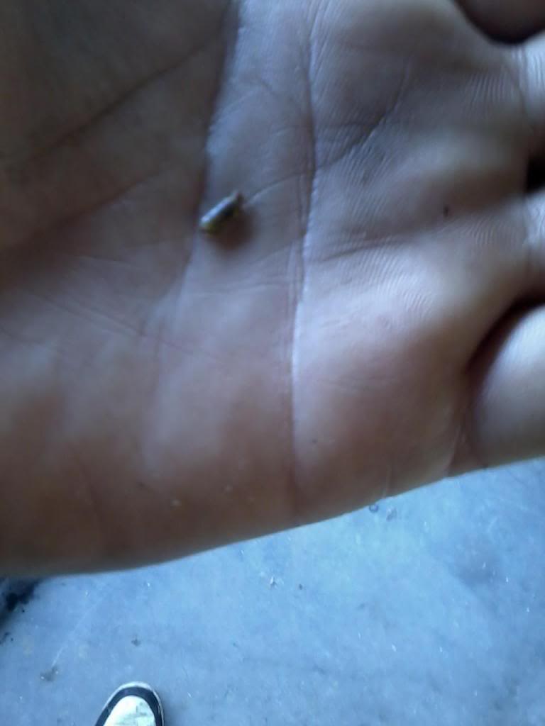
In the one time I seen it work it was because of a poor design in the Injector Harness due to a corroded wire crimp. It would even pass a resistance check.
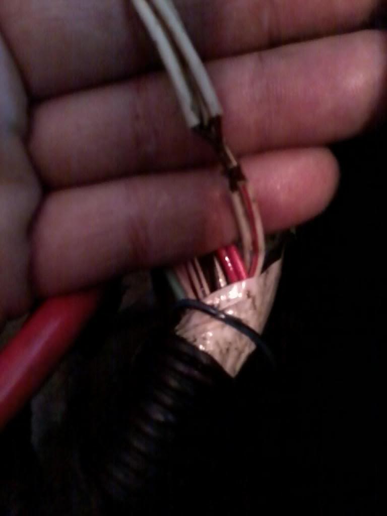
Some things to suspect is the crimp in the harness that I cut out and splice, solder, an shrink wrap and then wrap with electrical tape. I work on the 22re motor but think this would work on other motors as well.
On the 22re motor it is the Yellow and Blue Wires. Each one controls 2 injectors each.
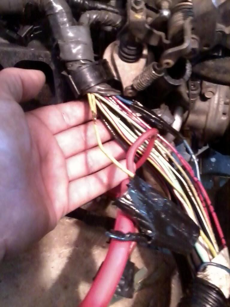
The ground wires for all 4 injectors have the same crimp and is White and White with Red stripe.
I have in the past seen it work and still not fire the injectors and my guess is the LED takes less electricity to operate then an injector. In this case it was all 4 injectors as it has been sitting for some time.
In the one time I seen it work it was because of a poor design in the Injector Harness due to a corroded wire crimp. It would even pass a resistance check.
Some things to suspect is the crimp in the harness that I cut out and splice, solder, an shrink wrap and then wrap with electrical tape. I work on the 22re motor but think this would work on other motors as well.

On the 22re motor it is the Yellow and Blue Wires. Each one controls 2 injectors each.

The ground wires for all 4 injectors have the same crimp and is White and White with Red stripe.

Last edited by Terrys87; Apr 18, 2014 at 10:49 AM.
Apr 18, 2014 | 01:46 PM
#7

Registered User


Joined: Jun 2011
Posts: 1,699
Likes: 75
I was working on a truck with Non Firing Injectors and wanted to pass on some information. I used the Light Emmitting Diode that is mentioned above and it works great. It would flicker bright and quick each time so I knew my computer was sending the signal. Remember the LED has to be in the correct way as a Diode will only allow current or voltage ( I am not strong in electricity) to pass in one direction.
I have in the past seen it work and still not fire the injectors and my guess is the LED takes less electricity to operate then an injector. In this case it was all 4 injectors as it has been sitting for some time.
In the one time I seen it work it was because of a poor design in the Injector Harness due to a corroded wire crimp. It would even pass a resistance check.
Some things to suspect is the crimp in the harness that I cut out and splice, solder, an shrink wrap and then wrap with electrical tape. I work on the 22re motor but think this would work on other motors as well.
you are right about the current required to fire the led being a lot less than what's required to reliably fire the injector, so don't use the led as proof positive that there isn't a corrosion problem in the harness.
if you own a 22re, best to just cut the harness open and remove all of the wiring in the spliced area... in my case, i had to also remove over a foot of the main ground wire, going back to the ecu box, because it was corroded inside the jacket of the wire itself.
since you are in there, you can also replace the injector terminals, at the end of the wiring harness.
i used a couple of different versions of self-fusing tape from lowes to wrap it up, as well as thick-walled shrink wrap right over each soldered connection... i also had to get a heavy-duty soldering iron.
voltage across, current through :-)
thx for an xlnt post!
Last edited by osv; Apr 18, 2014 at 01:51 PM.
Trending Topics
Apr 18, 2014 | 03:24 PM
#8
Registered User
Joined: Feb 2013
Posts: 167
Likes: 0
From: Hampton VA
As the poster above has said, LED's do work to tell you if there is a lack of injector pulse. But even if there is a pulse with an LED, does not mean the driver in the ECM or the power feed to the injectors can handle the current required to energize the injector coil. I have seen crank no starts with 1 shorted injector causing the PCM to shut down. But with a LED it would show a pulse.
Some times if you are just looking for a pulse on an injector or a coil, you can use a 194 or 906/912/921 series peanut light bulb. Bend the folded wire terminals strait and stick it in the plug, crank the engine and you have a $0.30 noid light.
Some times if you are just looking for a pulse on an injector or a coil, you can use a 194 or 906/912/921 series peanut light bulb. Bend the folded wire terminals strait and stick it in the plug, crank the engine and you have a $0.30 noid light.
Apr 18, 2014 | 03:38 PM
#9
Registered User
Joined: Feb 2013
Posts: 167
Likes: 0
From: Hampton VA
I was working on a truck with Non Firing Injectors and wanted to pass on some information. I used the Light Emmitting Diode that is mentioned above and it works great. It would flicker bright and quick each time so I knew my computer was sending the signal. Remember the LED has to be in the correct way as a Diode will only allow current or voltage ( I am not strong in electricity) to pass in one direction.
I have in the past seen it work and still not fire the injectors and my guess is the LED takes less electricity to operate then an injector. In this case it was all 4 injectors as it has been sitting for some time.
In the one time I seen it work it was because of a poor design in the Injector Harness due to a corroded wire crimp. It would even pass a resistance check.
Some things to suspect is the crimp in the harness that I cut out and splice, solder, an shrink wrap and then wrap with electrical tape. I work on the 22re motor but think this would work on other motors as well.

On the 22re motor it is the Yellow and Blue Wires. Each one controls 2 injectors each.

The ground wires for all 4 injectors have the same crimp and is White and White with Red stripe.

I have in the past seen it work and still not fire the injectors and my guess is the LED takes less electricity to operate then an injector. In this case it was all 4 injectors as it has been sitting for some time.
In the one time I seen it work it was because of a poor design in the Injector Harness due to a corroded wire crimp. It would even pass a resistance check.
Some things to suspect is the crimp in the harness that I cut out and splice, solder, an shrink wrap and then wrap with electrical tape. I work on the 22re motor but think this would work on other motors as well.
On the 22re motor it is the Yellow and Blue Wires. Each one controls 2 injectors each.
The ground wires for all 4 injectors have the same crimp and is White and White with Red stripe.
Just to elaborate more in the hopes it helps someone.
Resistance tests on wiring is USELESS unless you are looking for an open circuit. Anyone that is going to be chasing wiring problem needs a decent multimeter and needs to google "Voltage Drop Testing". There are some great you tube video's that will explain it. This is the proper way to test for high resistance on a circuit while in operation. Here is why.
Resistance test will send a small voltage with very little current down the wire, depending on the voltage that is returned it can calculate the resistance. Now you are testing an injector harness where each injector is drawing 8-10 amps of current at 13.6 volts. Every Stand of wire in the power circuit is broken except one little strand. Your multimeter will show good resistance because that one little strand can carry a small voltage and current fine. Now is that one little strand going to carry 10 amps? Not at all.
If you voltage drop test the circuit you will know quickly where your problem is. I'm not going to explain how to do it, just google it and hopefully it will help someone in the future. Plus you are not having to pay someone $109.00 an hour labor rate to do it for you,
Aug 4, 2014 | 08:59 PM
#10
Registered User
Joined: May 2014
Posts: 4
Likes: 0
Very timely thread. Just finished rebuilding my 87 22re and it would not start. No fuel to 1, 2 or 4. Bought the LED light and found signal on 1, 3 and 4 but not 2. Quite the puzzle. Undid the wiring harness and the splices "looked" good but I went ahead and cut them out and soldered the wires. Now I have signals on all four cylinders. Tomorrow, I'll put the intake back on and see what happens ...
Aug 5, 2014 | 12:50 AM
#11
Thread Starter
Super Moderator
iTrader: (1)
Joined: Aug 2008
Posts: 11,787
Likes: 28
From: Anderson Missouri
Thanks osv... I helped another guy with the same situation as you where they had to remove a foot or so of the ground wire. He said his was nearly a powder that the wiring was so corroded. A friend of mine was telling me about marine type electrical shrink wrap. He says when you apply heat to it, it has sealant like material that water proofs it. I have never tried it but next time I do I am going to look into getting some of it and see what my experience is like with it. I never knew that it exist.
Thanks stanprophet... Electrical is a weakness of mine and as you explained it where one wire will pass a current test when all others are broke, the injector still wont be able to fire. That was a hard lesson for me to learn, I thought if it had continuity, all was good. I since know better and glad you brought that point up. I
I was wondering if a peanut bulb would work. Next time I am into a harness I will give it a try. The reason I didn't try a bulb the first time I tried it was I thought that the pulse might not be powerful enough to light up the filament, or the filament might not react quick enough to light at the speed of the pulses.
With me being weak in electrical areas, it is nice to have others to help explain it or to improve on such a tool. Another thing I have tried and it does not work on, is I tried the LED for testing O2 sensors. It will not work on an 87 or older single wire O2 sensor. You have any suggestions for a tool for that?
Hello magistrate98.. I hope this will fix your problem. Like the poster above having the ground wire corroded and I know two others that had the same problem, might want to check for that if it doesn't fire up. Let us know your results and any other suggestions for tips or improvements for this tool. Luckily my local Radio Shack guy was able to help me figure out this for a tool, but I am sure there is room for improvements.
Aug 5, 2014 | 08:15 AM
#12

Registered User
Joined: Jul 2012
Posts: 1,776
Likes: 110
From: Northern Colorado
The only thing that will work for directly measuring an O2 sensor's output is a high impedance (>=10 Megohm) multimeter. The O2 sensor has a very high (>= 1Megohm) internal impedance, and putting a light bulb or LED across it will simply load it down so much that any voltage output will be undetectable. Even an analog volt-ohm meter will typically load the O2 sensor too much to provide useful information. Most digital multimeters will work, however.
Aug 5, 2014 | 08:30 AM
#13
Registered User
Joined: Mar 2012
Posts: 7,131
Likes: 683
Thank crimp in harsh environment of the engine compartment is surely a weak point. My truck sputtered after rebuilt engine was installed because of that.
Another evidence that back then Toyota had much better mechanical engineers than electrical engineers. The way to do it is twist wires together well, solder well, and insulate and weatherproof well -with good waterproofing shrink wrap, or let liquid electrical tape cure, then shrink wrap.
Good points. When I get a chance, I'll post where to apply 12V and ground and test points on injector pulsing circuit. However, does anyone know how long can someone apply voltage to injector while checking for voltage drops? A few seconds?
Another evidence that back then Toyota had much better mechanical engineers than electrical engineers. The way to do it is twist wires together well, solder well, and insulate and weatherproof well -with good waterproofing shrink wrap, or let liquid electrical tape cure, then shrink wrap.
... But even if there is a pulse with an LED, does not mean the driver in the ECM or the power feed to the injectors can handle the current required to energize the injector coil.
Some times if you are just looking for a pulse on an injector or a coil, you can use a 194 or 906/912/921 series peanut light bulb. Bend the folded wire terminals strait and stick it in the plug, crank the engine and you have a $0.30 noid light.
Some times if you are just looking for a pulse on an injector or a coil, you can use a 194 or 906/912/921 series peanut light bulb. Bend the folded wire terminals strait and stick it in the plug, crank the engine and you have a $0.30 noid light.
Aug 5, 2014 | 07:08 PM
#15
Registered User
Joined: Jun 2011
Posts: 1,699
Likes: 75
the shrink wrap that i used was thick, with the glue inside of it... really nice stuff.
for the record... those four wires that are spliced together are a deviation from the factory schematic, which shows two pair of wires coming off of the ecu, going to the injectors... the splice isn't on the schematic, so don't get freaked out when you see that they don't match.
two pair would infer that each pair has it's own driver chip, inside the ecu box, but i haven't pulled the lid on an ecu to verify... this is primitive fuel injection, so it's almost certainly batch-fired, which means that all injectors fire at the same time... which also means that fuel is getting squirted into the head at the wrong point in the 4-stroke engine cycle, for most of the injectors... once you get the rpm up, tho, it's not as bad as it sounds; at wot, batch-fired efi has traditionally made about the same horsepower as sequential fuel injection.
so the question is, why did toyota go in and splice wiring, on a harness that was already built per the schematic, and when did they do it? was there ever a recall for this? my harness looked like it had been worked on at least once after the splices were put in.
afaik, soldering automotive wiring together is not an accepted manufacturing procedure within the industry... it will corrode, at the minimum, but it should hold up fine for a number of years.
toyota wire is super high quality stuff; if you scrap one of these trucks, keep a harness for parts and/or backup.
Aug 5, 2014 | 07:34 PM
#16
Registered User
Joined: Jul 2012
Posts: 1,776
Likes: 110
From: Northern Colorado
The other reason that manufacturers use crimp connections for wiring is because it's so much faster. Takes about 2-3 seconds to make a good crimp joint, assuming you have the proper tools. Takes probably 5 times that long to properly clean and hand solder a wire connection.
Properly done, though, a soldered repair will indeed last a long time. It's better than a botched crimp done with cheap tools.
Aug 6, 2014 | 07:00 AM
#17

Registered User
Joined: Sep 2013
Posts: 1,631
Likes: 110
One issue I ran into with soldered connections to the older wiring near the engine is that the heat was weakening the connection/fusion between the solder and the wire. The older wiring usually has some corrosion that needs to be thoroughly cleaned, and cutting further back doesn't necessarily mean you'll get clean wires. This was the worst on the soldered connections for the injectors. I re-did those with the best crimps I could find, shrink wrap and one layer of thermal tape. Should bee good for a while.
Aug 6, 2014 | 07:47 AM
#18
Registered User
Joined: Jul 2012
Posts: 1,776
Likes: 110
From: Northern Colorado
Good point. If you're going to do soldered connections, the wires have to be squeaky clean. That means bright copper everywhere. That's can be hard to achieve on old stranded wire that's been cooking in the engine compartment for 20+ years, even if you strip back the insulation a couple of inches to try to find "virgin" wire.
Aug 6, 2014 | 07:31 PM
#19
Registered User
Joined: May 2014
Posts: 4
Likes: 0
Good point. If you're going to do soldered connections, the wires have to be squeaky clean. That means bright copper everywhere. That's can be hard to achieve on old stranded wire that's been cooking in the engine compartment for 20+ years, even if you strip back the insulation a couple of inches to try to find "virgin" wire.
My question now is how can I ensure the fuel pressure is high enough? I had Injector Experts clean my injectors. He's telling me I need at least 40 psi in the fuel rail or the injectors will not fire. So why is one cylinder getting fuel, thus implies one injector is firing? Yeah, I'm frustrated right now.
Aug 6, 2014 | 07:49 PM
#20
Registered User
Joined: Jul 2012
Posts: 1,776
Likes: 110
From: Northern Colorado
If your solder flowed onto the joints smoothly and was nice and shiny after it cooled, then your joints should be fine. They'll be well under 3 ohms.
Can't tell you about the fuel pressure.
Can't tell you about the fuel pressure.


