
SR5 Gauge Swap
 Nov 20, 2013 | 10:09 AM
#41

Registered User
Joined: Nov 2013
Posts: 3
Likes: 0
Part of this was posted by others over at the Marlin site, but I added to it & figure we could use our own swap thread over here in the pre-84 area. I think '79-81 trucks are different, but if you have an '82 or '83 with the "newer" style gauge, this will work.
**EDIT: The person who made this list came up with the numbers by counting every slot in the plug. The FSM numbers them differently because it only counts slots that have a wire in them, so don't try to compare the two or you'll get confused like I did!
It also seems better to use the wire #, as opposed to color, since some seem to be different. I'll post at the end of this thread what wire color I've got in what #slot. For that part I used the numbers from the FSM, not from this list below. Feel free to post here or PM me with any questions.
SR5----------Non-SR5---------Wire Color----Function
1<-----------------1-------------->GY------------>Right turn signal
2
3<-----------------3-------------->BR(B BR)------->Speed Sensor (-)
4<-----------------6-------------->GL------------->Speed Senson (+)
5
6
7<-----------------23------------->YG-------------->Water Temp
8<-----------------9-------------->RW-------------->Panel Lights (+)
9<----------------15-------------->YR--------------->Fuel Gauge
10<---------------12-------------->Y---------------->Ignition switch power
11<---------------21-------------->YB--------------->Oil Idiot Light
12<---------------22-------------->YW-------------->Charge Light
13<---------------14-------------->WB-------------->Ground
14<--------------------------------------------------Tach-must run a wire
15<---------------17----------------GB---------------Left Turn Signal
16----------------16----------------RB---------------Panel Lights (-)
17
18
19<---------------11---------------G-------------------4wd
20
21<---------------19---------------BY------------------Seat Belt
22
23<---------------13---------------RG------------------High Beam
24<---------------20---------------GW-----------------Brake
So if you get an SR5 cluster and simply plug it in to your truck, any of these wires that aren't the same number won't work. When I just plugged my cluster in, the right turn signal was all that worked. So you need to pull the wires from the corresponding number out of the plug and re-insert them into the SR5 location.
This shows what the back of the cluster looks like and the wire numbers. It also, if you can see it, shows you where the separate oil & volt cluster hooks in.
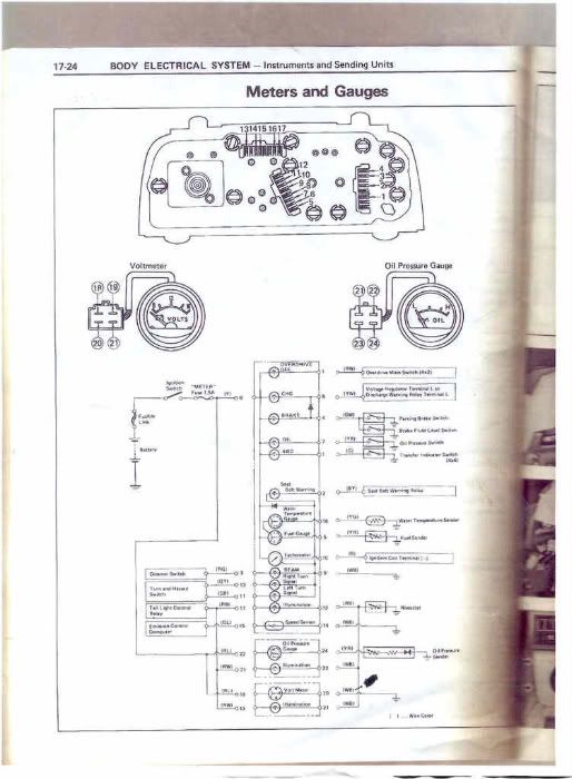
So to get the oil gauge & voltmeter working, you need to splice into the main cluster wires. You could get away with just splicing into hot wires here and there, but I liked doing it the way it would have been if it had been wired for it from the factory.
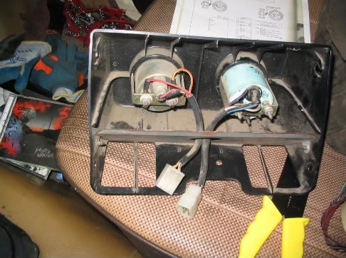
Back of gauges
Cut & labled
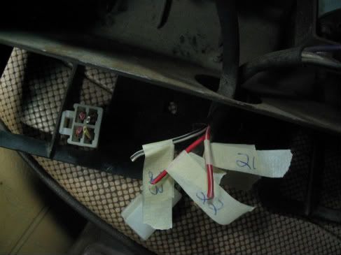
Connectors
My voltmeter ended up having some different wire colors than the FSM page listed, but they were all in the right location in the plug, so it was easy to figure out.
What I came up with after looking over the diagram is this, as far as what wires to tie the mini-cluster into:
Mini-------------Main
19 & 21(oil)---------->17
18 & 22-------------->6
21(volt) & 23--------->12
24------------------->Oil sending unit (SR5 model for GAUGE, not idiot light)
20------------------->Ground
Notice there is a #21 in each gauge for some reason.
If you want the oil idiot light and gauge to work, you need both sending units; one hooked up to the main cluster (switch), one hooked up to the new oil gauge (gauge). I just left the idiot light out..
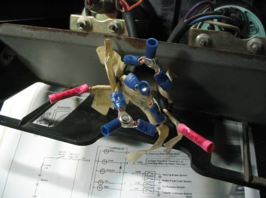
Splicing into main cluster
Connecting to mini-cluster (I used 16 gauge wire)
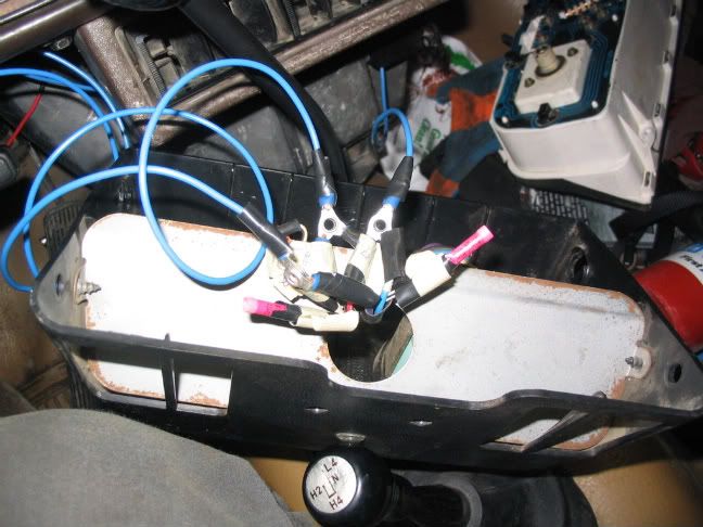
I'll need to pull the part that connects the wire to the oil sending unit off a truck in a junk yard & splice it in, but for now I just have the wire wrapped around the sending unit and it works fine, but I'm guessing it'll eventually vibrate off if I leave it that way. That's it, mine works great.
***Here are my wire color locations (using the FSM slot #'s)
1___2___3___4___
G___BY__RG__GW
5___6___7___8___9___10___11___12
YR__Y___YB__G__WB__Tach_GB___RB
13___14___15___16___17
GY__Br____GL___YG__RW
Remember, B is black, Br is brown, L is blue.
**EDIT: The person who made this list came up with the numbers by counting every slot in the plug. The FSM numbers them differently because it only counts slots that have a wire in them, so don't try to compare the two or you'll get confused like I did!
It also seems better to use the wire #, as opposed to color, since some seem to be different. I'll post at the end of this thread what wire color I've got in what #slot. For that part I used the numbers from the FSM, not from this list below. Feel free to post here or PM me with any questions.
SR5----------Non-SR5---------Wire Color----Function
1<-----------------1-------------->GY------------>Right turn signal
2
3<-----------------3-------------->BR(B BR)------->Speed Sensor (-)
4<-----------------6-------------->GL------------->Speed Senson (+)
5
6
7<-----------------23------------->YG-------------->Water Temp
8<-----------------9-------------->RW-------------->Panel Lights (+)
9<----------------15-------------->YR--------------->Fuel Gauge
10<---------------12-------------->Y---------------->Ignition switch power
11<---------------21-------------->YB--------------->Oil Idiot Light
12<---------------22-------------->YW-------------->Charge Light
13<---------------14-------------->WB-------------->Ground
14<--------------------------------------------------Tach-must run a wire
15<---------------17----------------GB---------------Left Turn Signal
16----------------16----------------RB---------------Panel Lights (-)
17
18
19<---------------11---------------G-------------------4wd
20
21<---------------19---------------BY------------------Seat Belt
22
23<---------------13---------------RG------------------High Beam
24<---------------20---------------GW-----------------Brake
So if you get an SR5 cluster and simply plug it in to your truck, any of these wires that aren't the same number won't work. When I just plugged my cluster in, the right turn signal was all that worked. So you need to pull the wires from the corresponding number out of the plug and re-insert them into the SR5 location.
This shows what the back of the cluster looks like and the wire numbers. It also, if you can see it, shows you where the separate oil & volt cluster hooks in.
So to get the oil gauge & voltmeter working, you need to splice into the main cluster wires. You could get away with just splicing into hot wires here and there, but I liked doing it the way it would have been if it had been wired for it from the factory.
Back of gauges
Cut & labled
Connectors
My voltmeter ended up having some different wire colors than the FSM page listed, but they were all in the right location in the plug, so it was easy to figure out.
What I came up with after looking over the diagram is this, as far as what wires to tie the mini-cluster into:
Mini-------------Main
19 & 21(oil)---------->17
18 & 22-------------->6
21(volt) & 23--------->12
24------------------->Oil sending unit (SR5 model for GAUGE, not idiot light)
20------------------->Ground
Notice there is a #21 in each gauge for some reason.
If you want the oil idiot light and gauge to work, you need both sending units; one hooked up to the main cluster (switch), one hooked up to the new oil gauge (gauge). I just left the idiot light out..
Splicing into main cluster
Connecting to mini-cluster (I used 16 gauge wire)
I'll need to pull the part that connects the wire to the oil sending unit off a truck in a junk yard & splice it in, but for now I just have the wire wrapped around the sending unit and it works fine, but I'm guessing it'll eventually vibrate off if I leave it that way. That's it, mine works great.
***Here are my wire color locations (using the FSM slot #'s)
1___2___3___4___
G___BY__RG__GW
5___6___7___8___9___10___11___12
YR__Y___YB__G__WB__Tach_GB___RB
13___14___15___16___17
GY__Br____GL___YG__RW
Remember, B is black, Br is brown, L is blue.
Nov 20, 2013 | 02:35 PM
#42
Thread Starter
Registered User
Joined: May 2008
Posts: 4,591
Likes: 126
From: Montana
I don't have time this week, but maybe Friday I'll post photos. There are two plugs that come off the coil. You just need to pick the right plug, and find the tach input on the back of the cluster and youre all set.
What year is your truck?
I have a photo in one of my albums of the wire coming out of the coil plug.
What year is your truck?
I have a photo in one of my albums of the wire coming out of the coil plug.
Nov 20, 2013 | 02:52 PM
#43
Registered User
Joined: Nov 2013
Posts: 3
Likes: 0
I don't have time this week, but maybe Friday I'll post photos. There are two plugs that come off the coil. You just need to pick the right plug, and find the tach input on the back of the cluster and youre all set.
What year is your truck?
I have a photo in one of my albums of the wire coming out of the coil plug.
What year is your truck?
I have a photo in one of my albums of the wire coming out of the coil plug.
Nov 21, 2013 | 07:53 AM
#44
Thread Starter
Registered User
Joined: May 2008
Posts: 4,591
Likes: 126
From: Montana
What do you mean by not having a pin? Is your cluster an SR5 cluster? If so, there's a place reserved for a tach wire. If not, all you can do is add an aftermarket tach.
If you pull the rubber boot off that plug, it should be obvious how to get the wire in there. I don't remember doing anything special...I think I just kind of jammed it in there, and it's held tight enough by the rubber boot that it isn't going anywhere. I don't own the truck I did this to anymore, so I can't go and look...
I didn't know anything about electricity when i did this stuff...I still don't now, but I know more. Notice i didn't even use different color wire for + and -....
So I didn't really know what I was doing. I just followed directions and it worked.
My guess, as far as grounding, is that between the tach signal and being hooked to the cluster, the power and ground is taken care of.
Nov 21, 2013 | 07:59 AM
#45
Thread Starter
Registered User
Joined: May 2008
Posts: 4,591
Likes: 126
From: Montana
Somewhere in my instructions is the location for the tach wire. The slots are numbered, and one of those numbers/slots is for the tach. I'm not 100% sure on the rigged solution you're talking about, but it might work.
With the majority of the work I do on my vehicles...right after I've done it, it's all very fresh in my memory and I know what's up. But now it's been a few years since I even looked at the back of a cluster...and honestly it's starting to fade.
With the majority of the work I do on my vehicles...right after I've done it, it's all very fresh in my memory and I know what's up. But now it's been a few years since I even looked at the back of a cluster...and honestly it's starting to fade.
Nov 21, 2013 | 08:03 AM
#46
Thread Starter
Registered User
Joined: May 2008
Posts: 4,591
Likes: 126
From: Montana
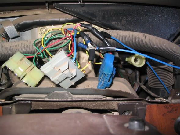
If you start counting from the bottom of my post you quoted...3rd photo up shows a blue wire stuffed into a slot in the plug for the back of the cluster.
Every other wire was pulled out of one location and moved to another location. The only wire I had to add was the tach. So that photo might help. It's showing the tach wire in the plug. But the actual numbered location is in this thread somewhere...
Every other wire was pulled out of one location and moved to another location. The only wire I had to add was the tach. So that photo might help. It's showing the tach wire in the plug. But the actual numbered location is in this thread somewhere...
Nov 21, 2013 | 09:02 AM
#47
Registered User
Joined: Nov 2013
Posts: 3
Likes: 0
If you start counting from the bottom of my post you quoted...3rd photo up shows a blue wire stuffed into a slot in the plug for the back of the cluster.
Every other wire was pulled out of one location and moved to another location. The only wire I had to add was the tach. So that photo might help. It's showing the tach wire in the plug. But the actual numbered location is in this thread somewhere...
Every other wire was pulled out of one location and moved to another location. The only wire I had to add was the tach. So that photo might help. It's showing the tach wire in the plug. But the actual numbered location is in this thread somewhere...
Nov 21, 2013 | 12:16 PM
#48
Thread Starter
Registered User
Joined: May 2008
Posts: 4,591
Likes: 126
From: Montana
Whatever my book said about, I posted in this thread. I sold the book with the truck.
There is a downloadable version of the 1983 FSM on this site.
I just stuffed the tach wire in there.
There is a downloadable version of the 1983 FSM on this site.
I just stuffed the tach wire in there.
Dec 30, 2014 | 09:39 PM
#49

Registered User

Joined: Aug 2013
Posts: 3
Likes: 0
From: Seattle, WA
Thank You, Thank You, Thank You!
I followed the gauge swap EXACTLY as written. First I labeled all the wires in each plug. Then I made the changes as described. I plugged it all back in and it worked perfectly! All I have left to do is the tach and I am done.
Another member posted that he found a empty plug hanging from the harness up under the dash behind the climate controls. It appears this plug is for the Volt/Oil gauge. Page 17-47 in the FSM (1982) seems to support my theory. All I need is the harness that goes from there to the gauge plugs (plus a sending unit swap out) and I have an SR5 dash.
Thank you for a well written tech article.
Dec 31, 2014 | 05:53 AM
#50
Thread Starter
Registered User
Joined: May 2008
Posts: 4,591
Likes: 126
From: Montana
Glad it worked for you!
It's funny looking back at it...I've since re-wired my entire camper, and looking at my wiring work for this gauge swap...wow! Pretty amateur! But that's cool. It all worked out.
It's funny looking back at it...I've since re-wired my entire camper, and looking at my wiring work for this gauge swap...wow! Pretty amateur! But that's cool. It all worked out.
May 11, 2016 | 05:31 PM
#51
Registered User
Joined: Aug 2011
Posts: 271
Likes: 3
From: Kansas City, Mo
This is a great write up... just did it on my truck 82 wiring harness.... its easy is you follow the way he counts from left to right on the connectors.
Still might put in a volt and oil pressure.....
I'd like to add that my tach I ran down to my Emissions box... tagged into the black wire.. bottom 3 over.... (from the left)
Still might put in a volt and oil pressure.....
I'd like to add that my tach I ran down to my Emissions box... tagged into the black wire.. bottom 3 over.... (from the left)

Thread
Thread Starter
Forum
Replies
Last Post
Flying91
86-95 Trucks & 4Runners (Build-Up Section)
45
Apr 11, 2024 04:39 PM
the1998sr5
95.5-2004 Tacomas & 96-2002 4Runners
15
Jul 14, 2020 08:35 PM
88yodabasket
86-95 Trucks & 4Runners
15
Jul 13, 2015 01:32 PM


