When you click on links to various merchants on this site and make a purchase, this can result in this site earning a commission. Affiliate programs and affiliations include, but are not limited to, the eBay Partner Network.
Here are the images from last week's adventures in cruise control.
Lube these before you start, located inside the wheel well, under the covers if you have them. Two weld nuts at the ends of the screw driver. Not the hole between them this is where the brake fluid switch clips to if you don't have the cruise control sub assembly. There are also two 10mm bolts thru the side of the inner fender, not shown I didn't pull the fender to prelube them.
Bolt at the end of the screw driver. Buried in mud. These are 12mm self tapping.
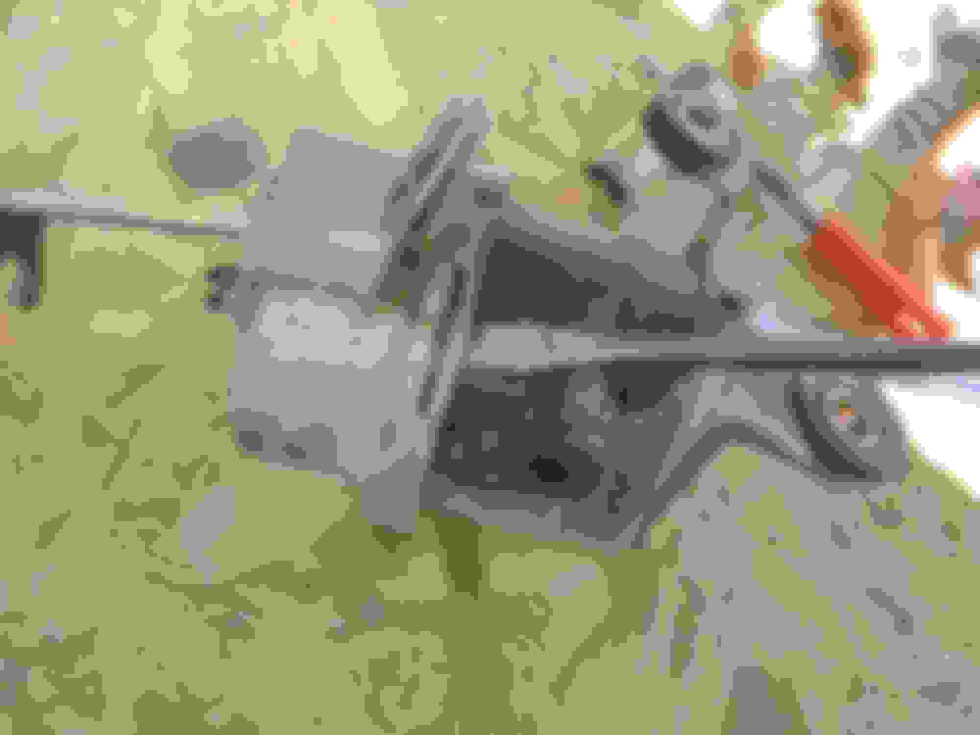
un bolt this once free from debris, I pulled the whole assembly as one but you may want to disassemble it, it will go back on easier without the pump in the way.
To the left this is where the dirt collects, just to the right under my vacuum pump is a wire harness clip.
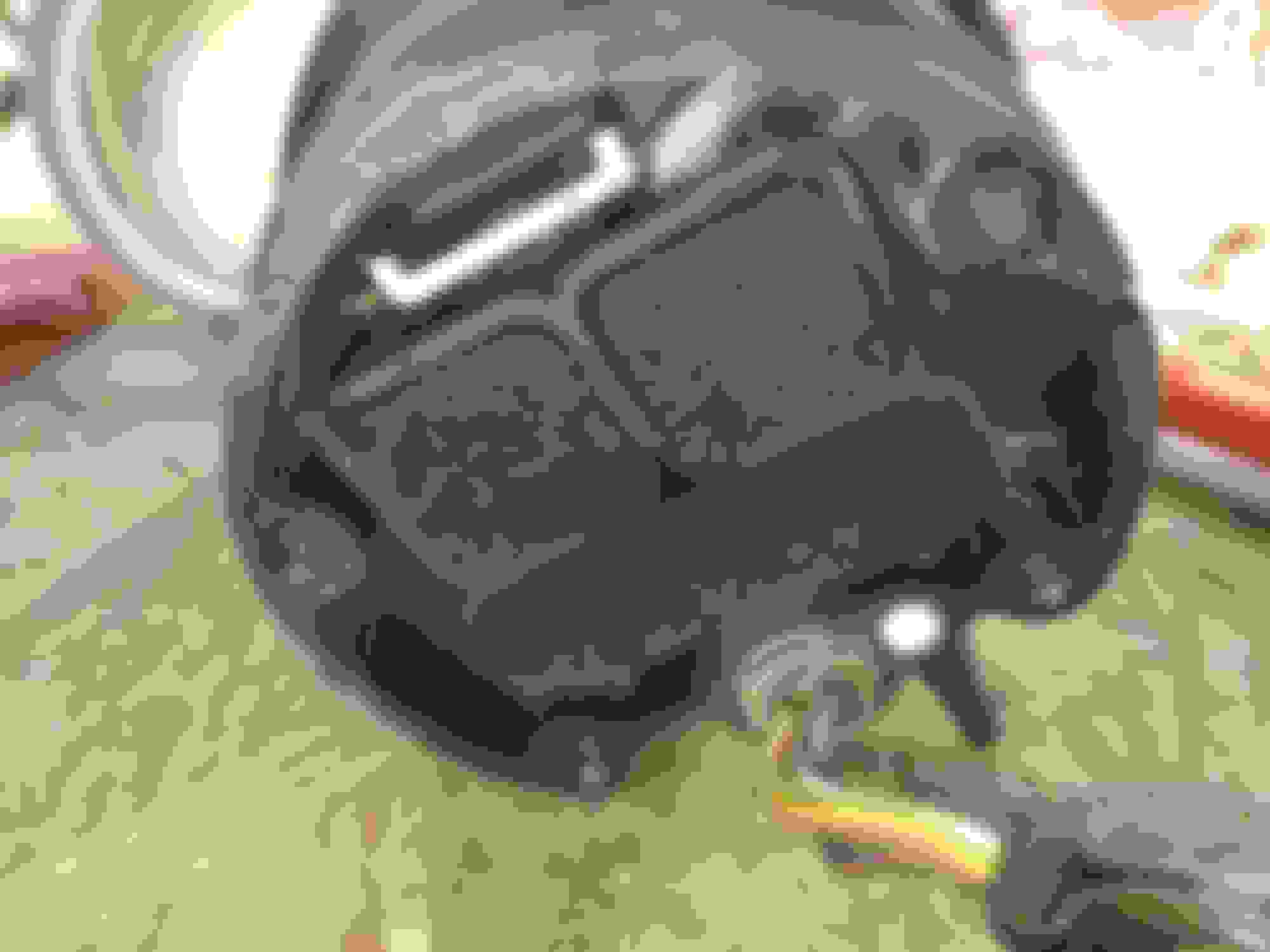
This is the brake master cylinder fluid switch wire, it clips to the sub assembly. Sorry bad pic. I broke mine, the dark line across the center.
Pry up the tabs on the can
Don't forget your match mark, if you do you'll have to rotate the can and might damage the diaphram
Here is the diaphragm without the shell
And remove the diaphragm to expose the return spring and valve coils.
Spring orientation, final wrap just above the screw.
Another angle, the spring seats between the screws and the housing and is a tight fit.
Remove the bottom cover to expose the filters. These will need replaced they will disentigrate when removed. You don't want the dust to enter the valves they cover, or the vacuum pump, or worse into the intake.
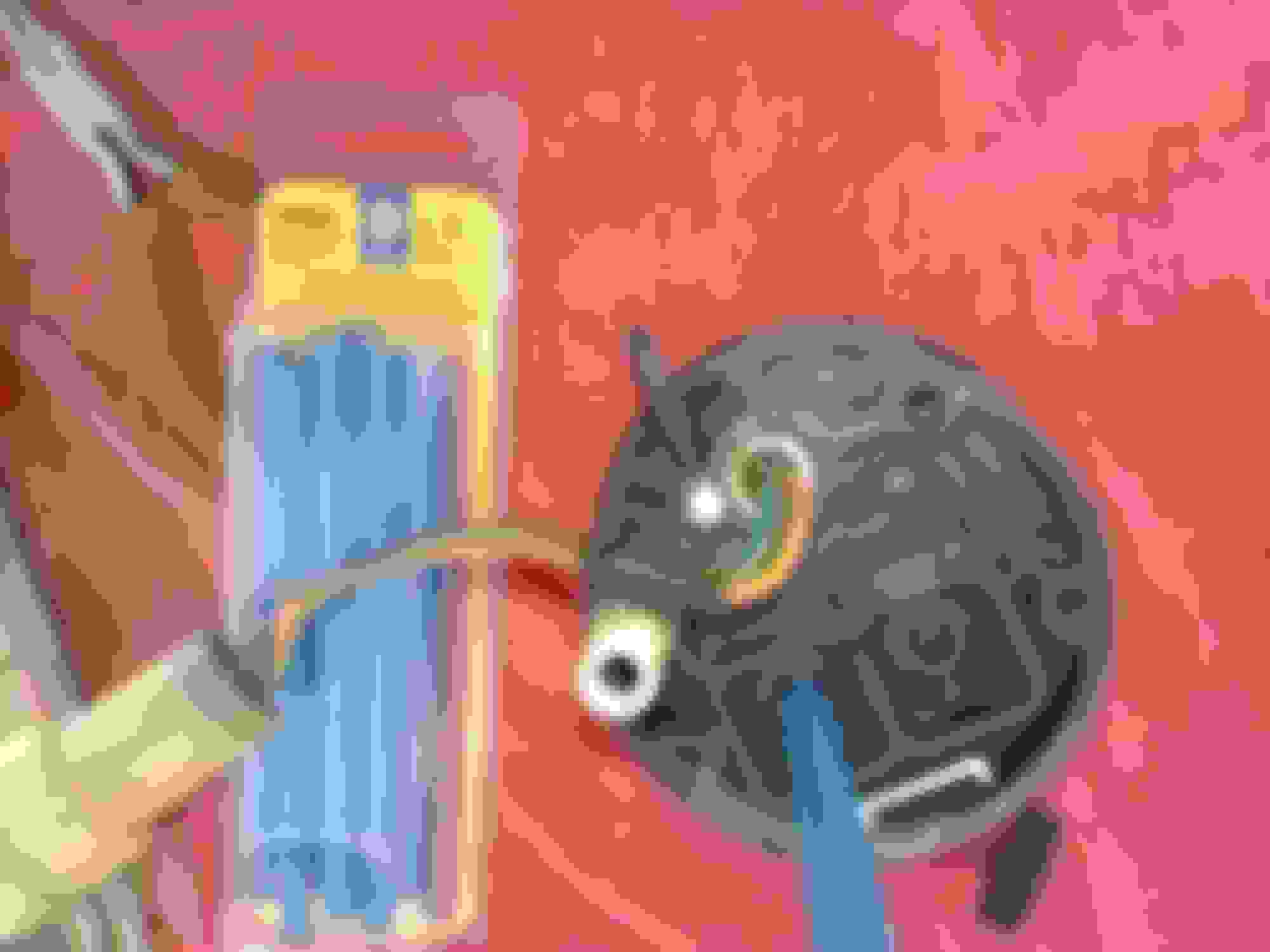
Here we check the valves with a bit of straw, hose, or in this case some shrink-wrap (Napa part number shown). Apply power to both coils and they should be sealed, no air flow.
Coil checks out Coil checks out
Minor cracking of the diaphragm. I coated it with permatex black and worked it into the crevices then gave it a topcoat
I also tested the vacuum switch and pump not shown. It was hillbilly, pump touched to battery with paper clips, vacuum switch got an oral exam.
Going to be tablet cam I'm lazy today. These are taken from the "Body electric" section of the 88 FSM.
. Schematic
. Inspection checklist
.
No one answered my question about type A codes. The 85 manual lists the same procedure (key on, set switch on and held while activating main cruise switch) so I'll just roll with that I guess the 86 is the same.
.
RAD/Ray in the upper right of the schematic above is what I was wondering about (Re: the PM). It ties into the charge fuse. Is that so it is deactivated when the battery is low or something? Guess I should reread the charging circuit explanation
im going to try to swap out for the 2nd gen runner tilt wheel with the cruise control buttons. clean that stupid cruise control off the dash.
*Drizzle* oh hi space
oh drat that reminded me to look into the 1st vs 2nd gen cruise control.
-controls
First gen set coast switches are simple switched grounds, second gen uses a resistor ladder.
First gen main switch houses the cruise control relay, second gen uses a separate relay.
First gen houses the indicator lamp in the main switch, second gen has a bulb in the combi-meter.
-computer
Both have a vacuum pump and pressure switch.
First gen connector is 18 pin (6,8,18 NC), second gen is 20 pin (7,9,20 NC)
First gen has no diagnostic terminal, second has a diagnostic terminal in DLC (for triggering type B codes).
First uses PKB to sense charge state, second uses STP+ (theory!)
-mechanical
First gen manipulates the throttle pedal, second connects to the throttle body.
Well that's the basic major differences, it will need a better going over but seems doable.
Converting requires the second gen wheel,slip ring and presumably the plugs, computer, main relay, dash lamp mod and cable. Presumably some wiring but nothing major.
Second generation has a cleaner diagnostic chart and some other goodies but no separate schematic diagram in the FSM which is a bummer it would simplify the conversion.
Dinner time I'll cut it off here before I start to ramble to much.
I am going to see what else I can find in the FSM for Cruise Control
Thank you sir!
can you provide the following 86 FSM pages from the "body electrical systems" section?
Index for reference, cruise control starts at BE-52 Schematic with interconnects Type A codes and diagnostics entry method Type B codes, and entry method Trouble shooting check list Inspections.
I don't know anything about 1st gen 'Runner cruise, and I don't have any schematics, but...
I do have an '87 SR5 'Runner whose cruise works. Anybody else have an early factory cruise that still works??
I will come hell and high water be damned! Lolz
At this point I'm leaning towards my battery voltage and charge circuit due to battery abuse effecting either the "charge" interlinking or the speed sensor output from the digital cluster. I still need to finish the computer inspection check list, speed sensor output and PKB signals.
I still need the owner's manual information regarding drive gear and overdrive. I got a response to my query but guy only has the German manual and it seems euro spec first gens have a manual throttle next to the parking brake not a full cruise control with computer. Which would be nice but not much better than a boot wedged to the transmission tunnel.
PS Terry thanks again, I see you added some from when I started responding there was only one image sent.
Millball, you can get yours into type A by that method listed above? (Key on, set on and held, mash main switch, release set. Then it will respond with the type A checks, accel and coast flash codes as above?)
Comparing the image Terry supplied with the 88 shows the same entry method, it's maybe worth noting the later model books say to hold it for 3seconds and the indicator is supposed to start blinking to confirm its in mode/type A output. I think I've held it that long or longer and it never flashes and didn't confirm the switch signals as it should and jumps right to type B when toggling "set" three times.
If you look above where I posted the inspection sheet I had about 9-10 volts coming from the STOP fuse which was pretty low. So low the I'm not certain if that or the cold was causing the main switch to not stay on.
There is also black box showing in the 95 cruise relay I'm not sure about, could be a regulator or just a distribution block. I wish they had a good upull yard up here it would be worth the entry fee just to get a look inside that relay.
Actually I just noticed the same box in the 86 main switch and an odd interconnect to the number 6 and 4 pins on the switch. Since the courtesy lamp for the ignition key is burned out I'll try to get a look at it.
If the rest of the inspection list checks out I'm maybe going to have to side line this untill I can get a stimulator board rigged up so I can feed the computer signals on the bench.
We're planning on heading back to the shop tomorrow to finish the downpipe if the flu doesn't get us also, everybody else is sick again. So looking very forward to having a proper exhaust system.
New heat shields, nothing fancy just enough to keep the radiation off the heater hoses.
Also want to get the blinkers attached with more than zip ties, it will be a quick and dirty bracket since it would only take a few minutes to bend some sheet to screw to. Have to decide on the corner lamp mod to use and can't hold off on the floppy signals it makes me nervous when I pull up behind the state troopers and know my signals look cross eyed half the time.
It should be warm enough to button up the rear panel again from the speaker amp repair over the next few days.
Two steps backwards, it seems my list keeps getting longer and longer.. with some luck I'll have some job interviews to attend this week and the budget will get a much needed influx and be able to get on to the little things!
Well poop that explains why the schematic you posted was the same. I have the 83, 85, and 88 in digital copy. Will have to pester Ray for those again, or just a confirmation they're the same as either of the 85 or 88 shown above.
I really think they are all the same. As far as 85/86 the only difference is the front axle. On all other electrical components I have ever worked on between 85/86 they were the same. I would think cruise would be the same as well but could be wrong.
Maybe this will help? I've been trying to hint around for you.
..clipped
I was just having a conversation the other day about the service manual. "Why don't you just get your own?" She says. My forehead crinkles and the eyebrows contort as my mind things of the price tag "I love you" I say lol. The next day I'm looking for an owner's manual and eBay started popping up FSM offerings at 200-250$ and could have crapped myself, they were 75-100 last I saw. We were just talking about the dwindling budget and 100$ was out of reach for a minor issue like having the 86 specific, hence the pulling a face at the suggestion..
Not relative I guess but funny, grab em when you see them for what might be a good price if you wait you might not like it..
speed sensor checks OK, NSS needed a little tweak, and the PKB signal is a little off 0.2v should be zero...
Recording the type 2 flashes and it's looking like a code 41..
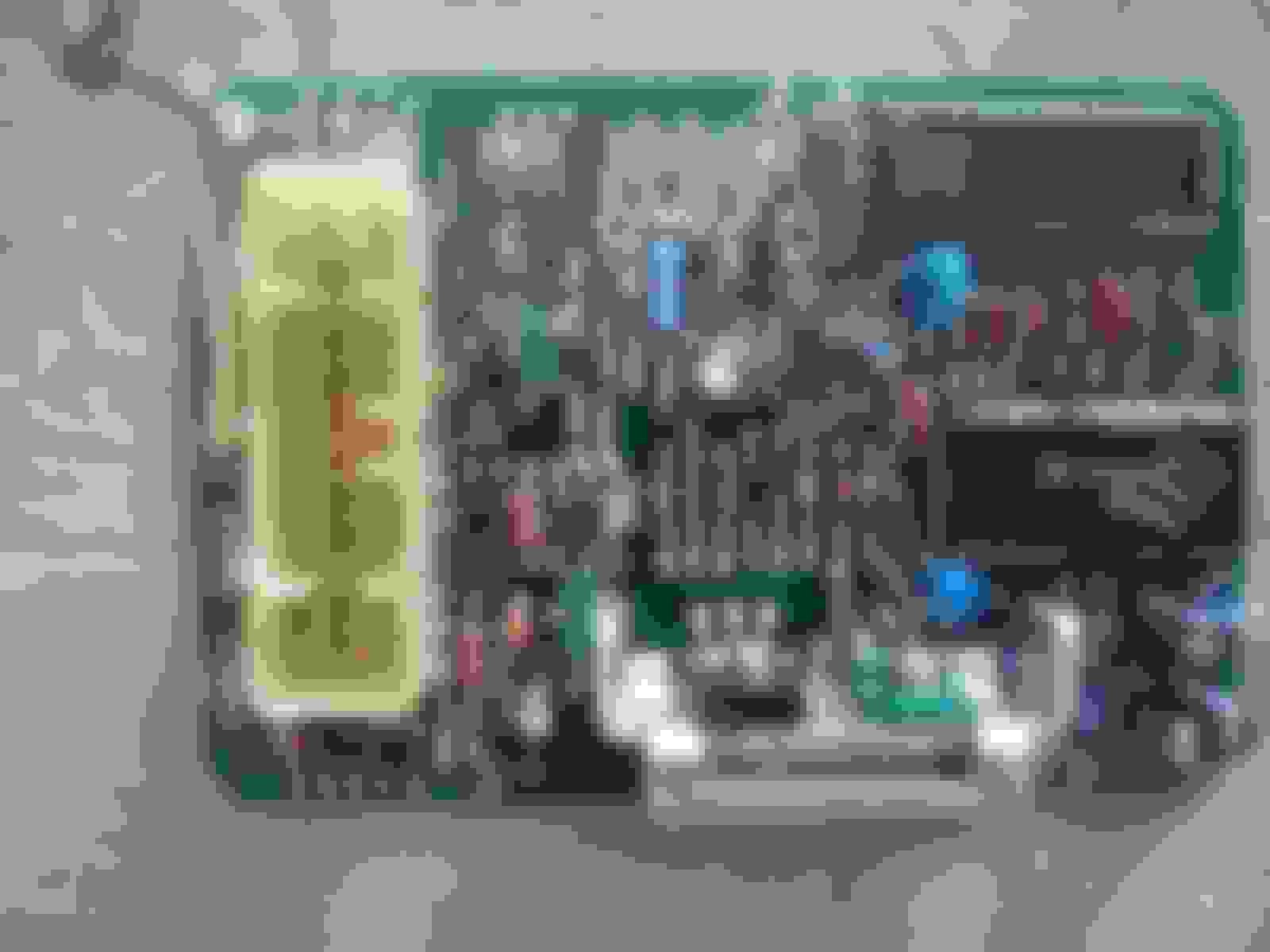
Got the little bastard on the bench now looking for loose solder joints. Next step is hunting down chip data yay... And testing transistors and diodes..
OK we have std Nippon sensor CPU marked
D151801-1180 (added the dash it's not really there)
421351M (probably a Toyota identification)
85-47 (production year-week)
In a 28 pin dip package..
8 to Jp1 NC
9 NC
10 is gnd
11-14 NC
27 to JP2 Gnd
I'm not able to locate Vin, it's going to be on a discreet style regulator I assume.
My harbor freight mm is showing its flaws, these probes aren't sharp enough to get thru the water proofing. Almost the whole board was dipped good for durability bad for signal probing..
Another Nippon denso IC marked
SE036 (maybe a driver chip, unsure)
1F09
No data on the second chip, SE068 came up in Google..
CPU is presumed to be a Motorola chip based on a little googling. I turned up a Kawasaki ECU (link) with similar denso part numbers. It should be relatively easy to identify based on the manufacturer, the pin count and a few known pin locations like VIN and GND.
I need some greybeard help, or an army of webcrawlers. Lol. 28pin Motorola IC from the mid eighties ring any bells? Something in the 6800 or 8051 series'?
At engineer pay I could have bought a handful of these already, one up in Montana on eBay for <40$
Anyways got a bit of a head ache, could be flu could be this circuit. Time for a break.
Well nap and dinner over I had another fresh look it's a headache for sure. I can't read resistor codes for one thing. Trying to map a circuit without modern computer programs is a bear! I spent half an hour scratching my head over a couple pins on the harness plug being tied together then realized it's probably the cancel switchs, then it tossed me a loop and I can't find a trace after it dives under a couple components.
I traced out the two input switchs coast and accel and they go to the SE chip, traced out the indicator to a transistor controlled by the CPU, located the CPU timing circuit.
To get a proper schematic it needs to be disassembled, and at this point I'm still thinking it's just one of the discreet parts that has failed (discreet parts means individual parts like resistors, diodes, transistors and such) the ICs seem to be accepting signals and communications are intact between them at least the set switch..
I'm generally of the mind you can't make a broken part worse by trying to fix it, intricate circuits are the exception can go from an easy fix to disasters in the blink of an eye.
Shameless bump, er sheet metal parts and a non-update
http://www.alfaparts.net/toyota4r84.htm
door bottoms, and wheel arch for the right side. 250+ shipping..
Could probably knock up the door panel at the kids shop.. but we've been slacking pretty bad..
Still stuck on the cruise computer. Don't have the kit to power it up on the bench and monitor signals. Thinking it's maybe a power up sequence problem which makes them act funny, if I could locate the reset pin on a pinout it would be a quick check but haven't found any pin data for the 28 pin version. Need a logic probe or oscilloscope.
Had a chrome browser update glitch that ate a bunch of my bookmarks, think I've got most of the denso CPU ones back
RAD/Ray in the upper right of the schematic above is what I was wondering about (Re: the PM). It ties into the charge fuse. Is that so it is deactivated when the battery is low or something? Guess I should reread the charging circuit explanation
Sorry, just saw this.
Yes, when Charge Light is on (Alt pin 2 is low or close to ground), brake fluid level switch closes, or brake switch closes that point on negative side of diode (same as Cruise Control pin 12) goes low. Pin12 going low is what disables CC when tapping the brake pedal. Charge fault will also disable it.
 02-01-2017, 12:07 PM