

 Feb 9, 2016, 10:13 AM
Last edit by: IB Advertising
See related guides and technical advice from our community experts:
Browse all: Interior Guides
- Toyota 4Runner 1984-1995 How to Swap Gauge Cluster
Step by step instructions for do-it-yourself repairs
Browse all: Interior Guides

SR5 Gauge Cluster Swap - How-to, with pics!
Apr 8, 2009 | 05:56 PM
#1
Thread Starter
Contributing Member
Joined: Feb 2008
Posts: 12,248
Likes: 33
From: Lake City, Fl
I got bored enough today, so I thought I'd throw my SR5 gauge cluster in my 91 Pickup, and take some pics along the way, and kinda do a half-way write up 
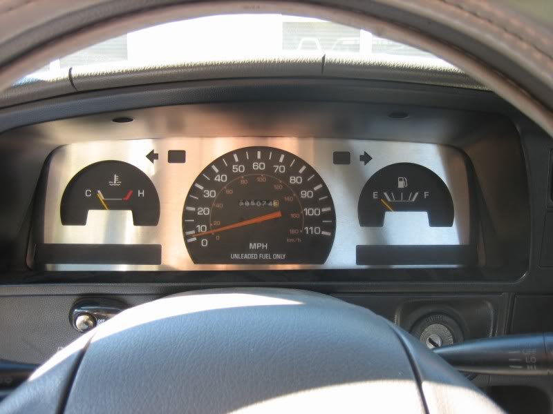
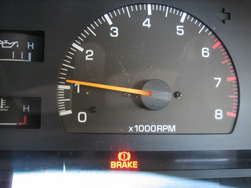
That's right, this is a basic write-up on how to turn this (obviously my original cluster wasn't stock anyway):
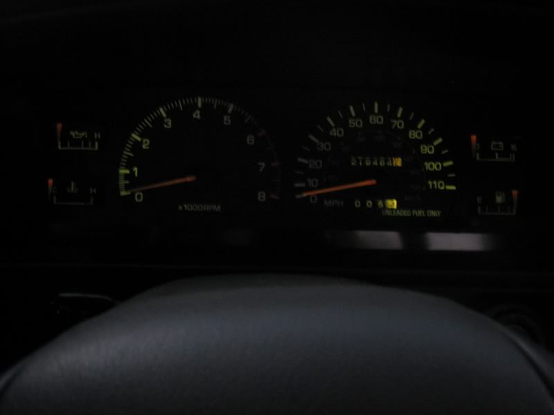
... into THIS!

!!! Special notes are at the bottom; be sure to check those out as well !!!
First thing you need to do, is obviously get yourself a gauge cluster out of an SR5 model Toyota. Be careful when choosing, because they are not ALL universal just because the body and interior look close to the same
The main determining factor is electronic speedometer and cable speedometer. I'm not 100% sure on the years (maybe someone can help out with this), but from what I can gather, the 1989 through 1991 models were more than likely all cable. After 1991 the electronic speedometer showed up, but I have heard instanced of the cable driven speedometers after 91 as well. Just to be certain, do youself a HUGE favor, and pull your current cluster out and have a look, just to make certain that you're looking for the right thing. You can also see the cable sticking out of the firewall and running down to the transmission if it is in fact a cable driven speedometer.
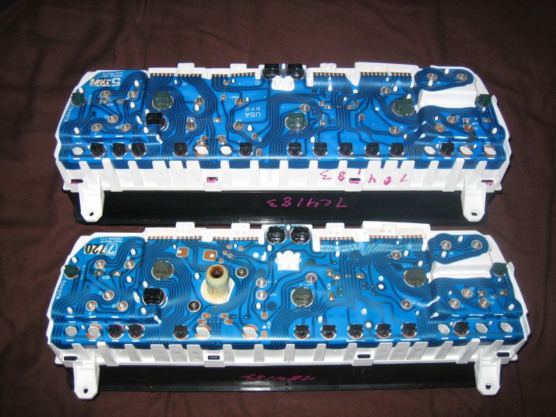
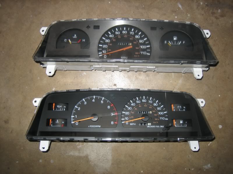
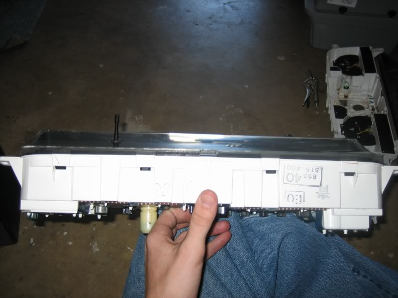
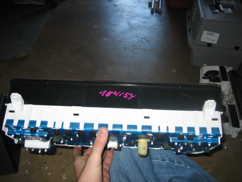
Cable driven clusters have the obvious cable input on the back, while the electronic speedometer type do not, but otherwise look identical when looking at it installed in the vehicle. You can see in the photo below, the top gauge cluster is the electronic one that is obviously missing the cable input that the bottom cluster has, but they are otherwise just about constructed the same:
So you've got you SR5 gauge cluster, CHECK!
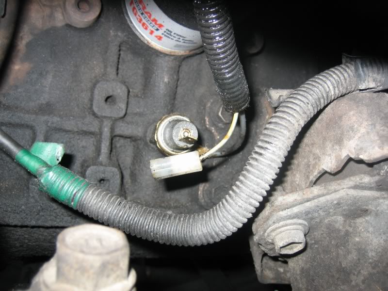
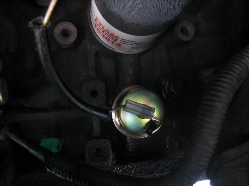
Before you even begin to tear into the dash to rip your old cluster out, it's a good idea to go ahead, reach into the fender on the passenger side, and unplug the oil pressure sender for the standard gauge pod. The reason for this is simple; if you don't, you WILL fry the oil pressure gauge in your newly gotten SR5 cluster. The stardard gauge pod doesn't have an oil pressure gauge to speak of, just a light that warns you of very little or no pressure. It does this by interrupting the groung in the curcit. The interruption is the stardard oil pressure sender. Because the SR5 models have an actual gauge to display the oil pressure in real-time, they require the sender that varies the resistance depending on oil pressure in order to allow the right amount of current to get to the gauge. If you don't install the correct sender, or at least unplug the standard sender for the time being, you will turn the key and see the oil pressure gauge on your SR5 cluster shoot all the way up to high for a little bit, and then it will drop back down. Once it drops back down, that's it; you've fried the oil pressue gauge, and you'll have to go source another SR5 cluster for the oil pressure gauge.
The reason I say to do this in the begining, just just so you wont get cought up in the moment of excitement over your new gauge install and forget about it
NOTE, this is on the 22re
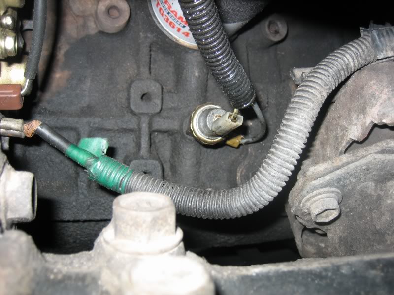
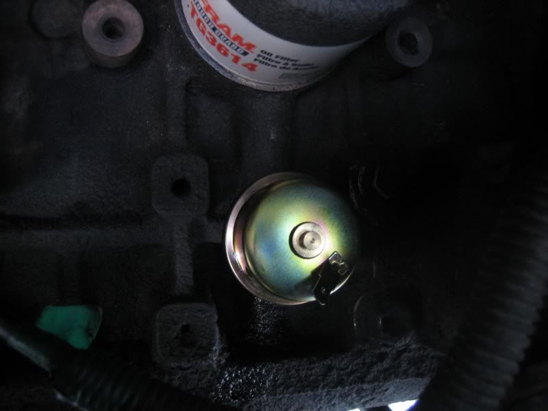
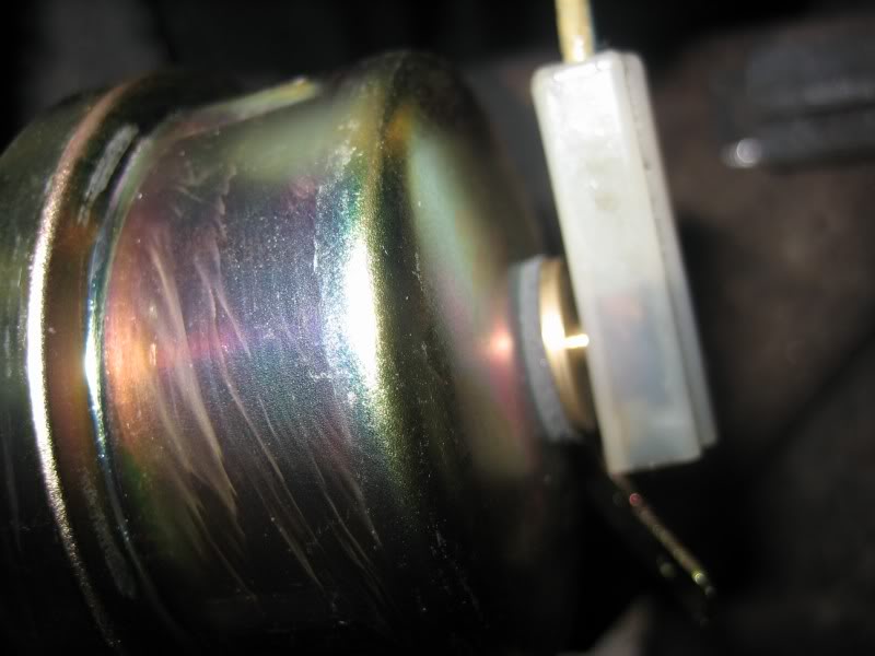
The sencor you want to replace your old sencor with will cost about 5 times more, but you'll need it in order to make your oil pressure gauge read:
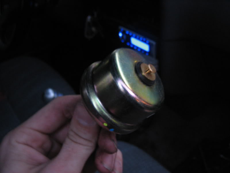
The original plug-in will still work though. Instead of plugging straight onto the sendor, the plug-in just slides onto the new sendor's tab with no modifications
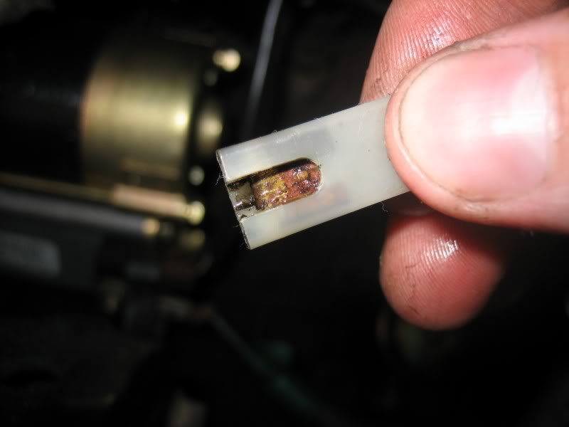
This one I have here, I later found to be defective as bought brand new, and if I were to have installed it, it just would have leaked so needless to say, I have to go without an oil pressure guage for the time being
Alright, now we can get to the fun parts
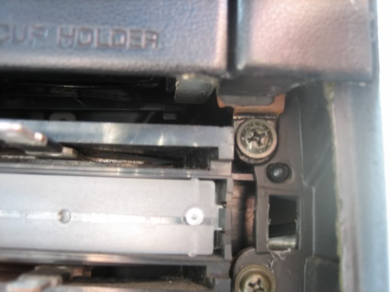
Probably the most annoying thing about swapping the gauge pod is the fact that the ENTIRE LOWER DASH has to be taken apart... In order to get the bezel in front of the gauge cluster out of the way, you have to remove the dash peice below it AND the center peice that surrounds the radio, beacause that center peice hides a screw just to the right of and under the cup holders, that holds that bezel in. And in order to get the center potion out, you have to remove the glove box and the rest of the passenger side lower dash out of the way...
Here's a picture of that hidden screw:
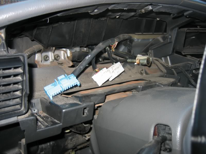
Once everything's out of the way, remove the 4 screws around the gauge cluster and pull it out just a little bit. This is were you find out (if you don't already know) if you have a cable driven cluster or an electronic cluster. On the electronic ones, just reach back behind the cluster and unplug the 4 plastic plug-ins along the top. If you're is cable driven (as mine is in my 91), unplug those 4 connections as well as the cable input, by pushing down on the little tab on the cable itself and simply pulling it out.
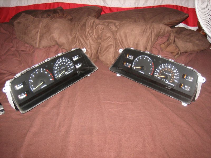
then, just compare your gauges, for fun, just to look at the old and the new
FOR CABLE SPEEDOMTER DRIVEN MODELS
You will probably notice that the cable input on the SR5 cluster is just a little bit different that the input on your standard cluster. Mine was in 2 ways.
1) the SR5 cluster had an adapter on it, making the input larger than what was on my standard cluster
fear not though, because it pulls right off after prying up the little locking tabs that hold it on:
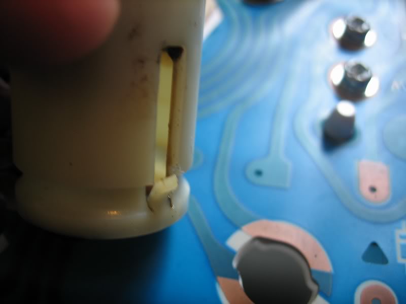
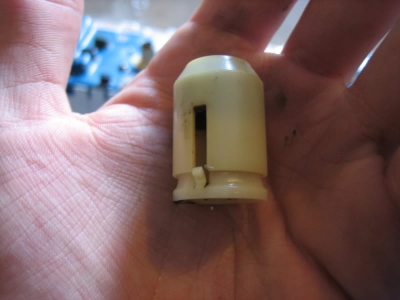
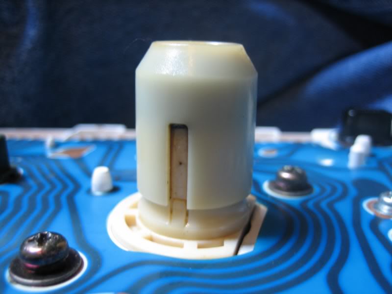
2) on the tip of the cable input still on the cluster, there was a small black plastic bushing, also easily removable with a pair of needle-nose pliers:
And that's it as far as making it fit!
For you guys with electronic speedometers, it's even easier. All you have to do is plug in the 4 connections on the back of the speedometer, and you're ready to rock and roll
The installation is simply the reverse of the removal! Slide the new cluster into place, plug in the 4 connections (and if yours it the cable driven speedometer, obviously slide on the cable until it snaps into place), push the cluster into place, and secure it with the 4 screws. Then put the rest of the dash together, starting with the bezel around the gauge cluster, then the center peice that surrounds the radio, and finish it off with the passenger and driver's side lower dash.
Finally, turn the key, make sure your dummy light such as the check engine light lights up, the brake light lights up, the volt meter rises, the gas gauge moves, and so on, then fire the ol girl up to see if the tachometer registers (see notes at the bottom about the tachometer)
And you are DONE ladies and gents! That is untill you install your new oil pressure sending unit, and/or if your tachometer doesn't work (see the notes at the bottom about the tach)
Take the truck for a test drive to make 100% sure the speedometer and the odometer is working correctly, and then enjoy your new gauges!
NOTES
1) It's a good idea to go ahead and replace ALL of the bulbs in the cluster while you have it out, just beause it's so much hassle to remove the entire dash just to replace some burned out bulbs. I learned this lesseon myself the hard way, beause I now see that after putting all the dash back together, the center back-light bulb is burned out...
2) I mentioned about the tach not working in some instances. It's been an ongoing question about what determines if you truck is pre-wired for the tach funtion. Many speculate it's the year. Many think that it's just dumb-luck, and if you draw a lucky card, you're already wired for a tach-equiped gauge cluster. I have no guess on the subject. I was lucky enough to have the tach wiring already in place in my 91 Pickup DLX, so mine was just plug and play. So unfotunately because of that, I didn't have to run my own tach wire, so I do not have any info on doing that myself. Perhaps someone can contribute and post a solution and a short how-to on this
3) For an easier installation, choose a gauge cluster out of an SR5 that has the same size motor as your truck, for the purpose of the tach registering right without needing adjustments. If it isn't possible for you to get a hold of a cluster out of a donor vehicle with the same engine as yours, fear not, as one of the users here, twistedsymphony, has shown us how to dive into the cluster and adjust a potentimeter in order to dial in the resistance in the cluster and make it read correctly no matter what you took it out of or are putting it in
Thank you for this twistedsymphony!
-------------------------------
The adjustment potentiometer:
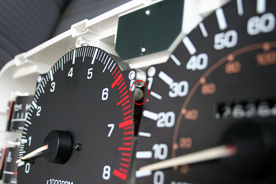
If you have another tach hooked up, you can use it to compare to the SR5 tach and make adjustments on the fly. You can sneak a thin and long screw driver in there to adjust the potentiometer (I had to gently push against the pot with the driver to bend it back slightly and seat, but this shouldn't cause any harm).
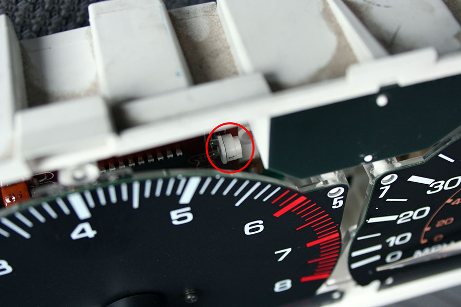
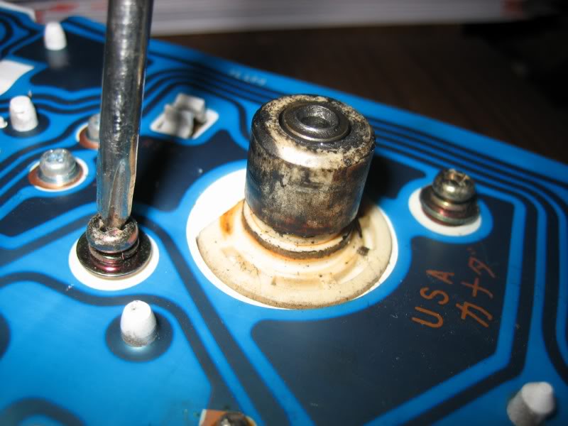
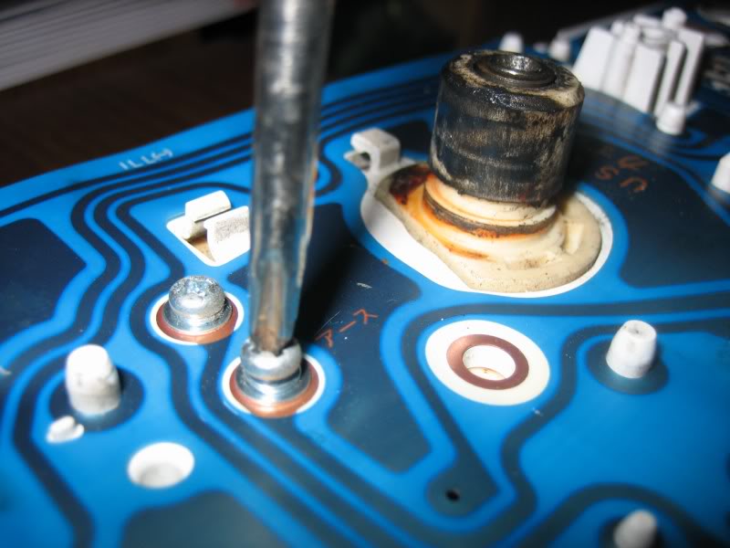
If you don't have another tach to compare to and adjust by, you can pull the tachometer assembly out of the cluster by removing these 3 screws:
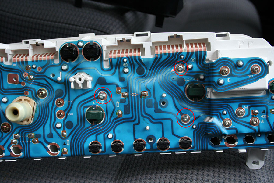
Then use your multimeter to measure resistance across these two points on the rear of the electronics board that the tach is mounted on:
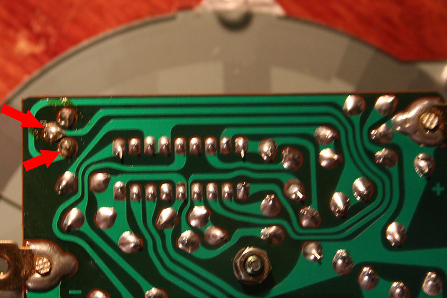
The V6 was originally setup with a value of 44.9K ohms, I adjusted it to 63.8K ohms.
I would recommend people converting a 6cyl cluster to a 4cyl cluster to simply add 20K ohms to whatever they started with.
This cluster came out of a 1992 4Runner Automatic V6 SR5, and I installed it in my 1989 Pikcup 5-speed 22re Deluxe, so considering that, you can make anything work with anything.
---------------------------------

That's right, this is a basic write-up on how to turn this (obviously my original cluster wasn't stock anyway):
... into THIS!
!!! Special notes are at the bottom; be sure to check those out as well !!!
First thing you need to do, is obviously get yourself a gauge cluster out of an SR5 model Toyota. Be careful when choosing, because they are not ALL universal just because the body and interior look close to the same
The main determining factor is electronic speedometer and cable speedometer. I'm not 100% sure on the years (maybe someone can help out with this), but from what I can gather, the 1989 through 1991 models were more than likely all cable. After 1991 the electronic speedometer showed up, but I have heard instanced of the cable driven speedometers after 91 as well. Just to be certain, do youself a HUGE favor, and pull your current cluster out and have a look, just to make certain that you're looking for the right thing. You can also see the cable sticking out of the firewall and running down to the transmission if it is in fact a cable driven speedometer.
Cable driven clusters have the obvious cable input on the back, while the electronic speedometer type do not, but otherwise look identical when looking at it installed in the vehicle. You can see in the photo below, the top gauge cluster is the electronic one that is obviously missing the cable input that the bottom cluster has, but they are otherwise just about constructed the same:
So you've got you SR5 gauge cluster, CHECK!
Before you even begin to tear into the dash to rip your old cluster out, it's a good idea to go ahead, reach into the fender on the passenger side, and unplug the oil pressure sender for the standard gauge pod. The reason for this is simple; if you don't, you WILL fry the oil pressure gauge in your newly gotten SR5 cluster. The stardard gauge pod doesn't have an oil pressure gauge to speak of, just a light that warns you of very little or no pressure. It does this by interrupting the groung in the curcit. The interruption is the stardard oil pressure sender. Because the SR5 models have an actual gauge to display the oil pressure in real-time, they require the sender that varies the resistance depending on oil pressure in order to allow the right amount of current to get to the gauge. If you don't install the correct sender, or at least unplug the standard sender for the time being, you will turn the key and see the oil pressure gauge on your SR5 cluster shoot all the way up to high for a little bit, and then it will drop back down. Once it drops back down, that's it; you've fried the oil pressue gauge, and you'll have to go source another SR5 cluster for the oil pressure gauge.
The reason I say to do this in the begining, just just so you wont get cought up in the moment of excitement over your new gauge install and forget about it
NOTE, this is on the 22re
The sencor you want to replace your old sencor with will cost about 5 times more, but you'll need it in order to make your oil pressure gauge read:
The original plug-in will still work though. Instead of plugging straight onto the sendor, the plug-in just slides onto the new sendor's tab with no modifications
This one I have here, I later found to be defective as bought brand new, and if I were to have installed it, it just would have leaked
so needless to say, I have to go without an oil pressure guage for the time beingAlright, now we can get to the fun parts
Probably the most annoying thing about swapping the gauge pod is the fact that the ENTIRE LOWER DASH has to be taken apart... In order to get the bezel in front of the gauge cluster out of the way, you have to remove the dash peice below it AND the center peice that surrounds the radio, beacause that center peice hides a screw just to the right of and under the cup holders, that holds that bezel in. And in order to get the center potion out, you have to remove the glove box and the rest of the passenger side lower dash out of the way...
Here's a picture of that hidden screw:
Once everything's out of the way, remove the 4 screws around the gauge cluster and pull it out just a little bit. This is were you find out (if you don't already know) if you have a cable driven cluster or an electronic cluster. On the electronic ones, just reach back behind the cluster and unplug the 4 plastic plug-ins along the top. If you're is cable driven (as mine is in my 91), unplug those 4 connections as well as the cable input, by pushing down on the little tab on the cable itself and simply pulling it out.
then, just compare your gauges, for fun, just to look at the old and the new
FOR CABLE SPEEDOMTER DRIVEN MODELS
You will probably notice that the cable input on the SR5 cluster is just a little bit different that the input on your standard cluster. Mine was in 2 ways.
1) the SR5 cluster had an adapter on it, making the input larger than what was on my standard cluster
fear not though, because it pulls right off after prying up the little locking tabs that hold it on:
2) on the tip of the cable input still on the cluster, there was a small black plastic bushing, also easily removable with a pair of needle-nose pliers:
And that's it as far as making it fit!
For you guys with electronic speedometers, it's even easier. All you have to do is plug in the 4 connections on the back of the speedometer, and you're ready to rock and roll
The installation is simply the reverse of the removal! Slide the new cluster into place, plug in the 4 connections (and if yours it the cable driven speedometer, obviously slide on the cable until it snaps into place), push the cluster into place, and secure it with the 4 screws. Then put the rest of the dash together, starting with the bezel around the gauge cluster, then the center peice that surrounds the radio, and finish it off with the passenger and driver's side lower dash.
Finally, turn the key, make sure your dummy light such as the check engine light lights up, the brake light lights up, the volt meter rises, the gas gauge moves, and so on, then fire the ol girl up to see if the tachometer registers (see notes at the bottom about the tachometer)
And you are DONE ladies and gents! That is untill you install your new oil pressure sending unit, and/or if your tachometer doesn't work (see the notes at the bottom about the tach)
Take the truck for a test drive to make 100% sure the speedometer and the odometer is working correctly, and then enjoy your new gauges!
NOTES
1) It's a good idea to go ahead and replace ALL of the bulbs in the cluster while you have it out, just beause it's so much hassle to remove the entire dash just to replace some burned out bulbs. I learned this lesseon myself the hard way, beause I now see that after putting all the dash back together, the center back-light bulb is burned out...
2) I mentioned about the tach not working in some instances. It's been an ongoing question about what determines if you truck is pre-wired for the tach funtion. Many speculate it's the year. Many think that it's just dumb-luck, and if you draw a lucky card, you're already wired for a tach-equiped gauge cluster. I have no guess on the subject. I was lucky enough to have the tach wiring already in place in my 91 Pickup DLX, so mine was just plug and play. So unfotunately because of that, I didn't have to run my own tach wire, so I do not have any info on doing that myself. Perhaps someone can contribute and post a solution and a short how-to on this
3) For an easier installation, choose a gauge cluster out of an SR5 that has the same size motor as your truck, for the purpose of the tach registering right without needing adjustments. If it isn't possible for you to get a hold of a cluster out of a donor vehicle with the same engine as yours, fear not, as one of the users here, twistedsymphony, has shown us how to dive into the cluster and adjust a potentimeter in order to dial in the resistance in the cluster and make it read correctly no matter what you took it out of or are putting it in
Thank you for this twistedsymphony!
-------------------------------
The adjustment potentiometer:
If you have another tach hooked up, you can use it to compare to the SR5 tach and make adjustments on the fly. You can sneak a thin and long screw driver in there to adjust the potentiometer (I had to gently push against the pot with the driver to bend it back slightly and seat, but this shouldn't cause any harm).
If you don't have another tach to compare to and adjust by, you can pull the tachometer assembly out of the cluster by removing these 3 screws:
Then use your multimeter to measure resistance across these two points on the rear of the electronics board that the tach is mounted on:
The V6 was originally setup with a value of 44.9K ohms, I adjusted it to 63.8K ohms.
I would recommend people converting a 6cyl cluster to a 4cyl cluster to simply add 20K ohms to whatever they started with.
This cluster came out of a 1992 4Runner Automatic V6 SR5, and I installed it in my 1989 Pikcup 5-speed 22re Deluxe, so considering that, you can make anything work with anything.
---------------------------------
Last edited by iamsuperbleeder; Jun 13, 2010 at 06:43 PM.
Apr 8, 2009 | 06:44 PM
#2
Registered User
Joined: Jul 2008
Posts: 4,592
Likes: 0
From: Grew up in S.C.V, So Cal.....now in Hampstead, NC
And just think, it took 5 times longer to do the write up, than it did the actual swap. 'Bleeder, if all that work took you longer than 20 min, (swapping the sender and all), you really need to stop drinking while modding.....!
Apr 8, 2009 | 07:47 PM
#3
Thread Starter
Contributing Member
Joined: Feb 2008
Posts: 12,248
Likes: 33
From: Lake City, Fl
but half the time in the swap was pausing to take pictures

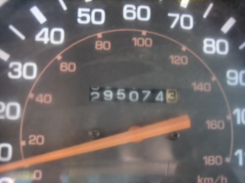
I also got into it and tried to swap the odometers out so I could keep my 295k speedometer, but I kinda broke the old one in the process

I'll see if I can't clock this one on up there though
Last edited by iamsuperbleeder; Apr 8, 2009 at 07:48 PM.
Apr 8, 2009 | 08:18 PM
#6
Thread Starter
Contributing Member
Joined: Feb 2008
Posts: 12,248
Likes: 33
From: Lake City, Fl
thank you RMA!
it was a quicky; it could be better
I'm open to any suggestions from you guys to make it any better as well


Trending Topics
Apr 8, 2009 | 10:34 PM
#9
Registered User
Joined: Aug 2007
Posts: 5,334
Likes: 4
From: Vian, OK
sooo..theres this 85 reg cab 4x4 at the junkyard...no motor..or trans..or t-case..(has front axle though) and it has the SR5 cluster...
my cluster is SUPER EASY to take out..its just 4-6 screws..then the plugs on the back...
so while i have my cluster out...WHICH WIRE IS THE TACH WIRE???...what does it look like...that way when i DO do the cluster/LEB bulb swap..i'll know what im doing right away..
thanks Bleeder
my cluster is SUPER EASY to take out..its just 4-6 screws..then the plugs on the back...
so while i have my cluster out...WHICH WIRE IS THE TACH WIRE???...what does it look like...that way when i DO do the cluster/LEB bulb swap..i'll know what im doing right away..
thanks Bleeder
Apr 9, 2009 | 08:58 AM
#10
Thread Starter
Contributing Member
Joined: Feb 2008
Posts: 12,248
Likes: 33
From: Lake City, Fl
well luckily it was the odometer on the old stock cluster that I broke, not the one in the SR5 cluster I didn't break the odometer itself, but rather the coiled spring mechanism that returns the speedo needle back to zero when you stop (well I broke the needle too ). the odometer portions are identical between the standard and SR5 models believe it or not, with the acception of a couple removable parts (risers that hold the face onto the standard gauge, and a bushing on the pin that needle presses onto). the SR5 just has the mileage-trip on it.
but the new one's working great! I'm on my lunch break at work right now, and so far I've put 23 miles on it but later on tonight I'll post the pics of my attempt to swap the odometers
as far as that tach wire Camo, I honestly don't know, especially on an 85. all that I can tell you is that there are 3 screws that hold it into the cluster, and each of those is an electrical contact with the plastic sheet-electronic board on the back. thoeretically, one should be ignition 12+, one should be ground -, and the third should be the tach signal. normally that hooks to the - post on the ignition coil, but I guess it could be different on an OEM tach... like mentioned above, luckily mine was already wired, so I didn't have to mess with it
I didn't break the odometer itself, but rather the coiled spring mechanism that returns the speedo needle back to zero when you stop (well I broke the needle too ). the odometer portions are identical between the standard and SR5 models believe it or not, with the acception of a couple removable parts (risers that hold the face onto the standard gauge, and a bushing on the pin that needle presses onto). the SR5 just has the mileage-trip on it.but the new one's working great! I'm on my lunch break at work right now, and so far I've put 23 miles on it
but later on tonight I'll post the pics of my attempt to swap the odometersas far as that tach wire Camo, I honestly don't know, especially on an 85. all that I can tell you is that there are 3 screws that hold it into the cluster, and each of those is an electrical contact with the plastic sheet-electronic board on the back. thoeretically, one should be ignition 12+, one should be ground -, and the third should be the tach signal. normally that hooks to the - post on the ignition coil, but I guess it could be different on an OEM tach... like mentioned above, luckily mine was already wired, so I didn't have to mess with it
Apr 9, 2009 | 09:39 AM
#11
Registered User
Joined: Jul 2008
Posts: 4,592
Likes: 0
From: Grew up in S.C.V, So Cal.....now in Hampstead, NC
Really good write up, 'Bleeder, all joking aside. When I get my body lift, hopefully in the next week or so, (I sent the money last sat), you wanna come out to Wa and do the write up of my install???? lol
Apr 9, 2009 | 11:21 AM
#12
Registered User
Joined: May 2007
Posts: 91
Likes: 0
From: Lancaster, PA
Nice write-up. I'm going to do this swap as well.
What oil pressure sensor/switch did you use? When i looked one up there was 2 for the guage. There was a yazaki and denso. I've been searching alittle on this and seem like you have to match it with the cluster you have? there should be a name on the back of the cluster?(i didnt receive my cluster yet) can someone clarify this?
What oil pressure sensor/switch did you use? When i looked one up there was 2 for the guage. There was a yazaki and denso. I've been searching alittle on this and seem like you have to match it with the cluster you have? there should be a name on the back of the cluster?(i didnt receive my cluster yet) can someone clarify this?
Last edited by HAI-TEK7; Apr 9, 2009 at 11:24 AM.
Apr 9, 2009 | 11:38 AM
#13
Nice write-up. I'm going to do this swap as well.
What oil pressure sensor/switch did you use? When i looked one up there was 2 for the guage. There was a yazaki and denso. I've been searching alittle on this and seem like you have to match it with the cluster you have? there should be a name on the back of the cluster?(i didnt receive my cluster yet) can someone clarify this?
What oil pressure sensor/switch did you use? When i looked one up there was 2 for the guage. There was a yazaki and denso. I've been searching alittle on this and seem like you have to match it with the cluster you have? there should be a name on the back of the cluster?(i didnt receive my cluster yet) can someone clarify this?
Right one:

WRONG one:

Last edited by BigBluePile; Apr 9, 2009 at 11:43 AM.
Apr 9, 2009 | 12:29 PM
#14
Registered User
Joined: Dec 2008
Posts: 1,015
Likes: 0
From: DFW, Texas!
The tach signal is one of the lines in one (or more) of the three plugs. There's not a standalone "tach wire".
Apr 9, 2009 | 12:36 PM
#15
Registered User
Joined: Dec 2008
Posts: 1,015
Likes: 0
From: DFW, Texas!
The "wrong one" runs in the $10-20 range, the "right one" is $40-60.
First one I got at Pep Boys, I mangled it nicely, punted, and bought one from Toyota parts desk -- Toyota's price was pretty much the same. The only gotcha about getting this at Toyota is they often use your VIN to pull up the parts fiche. If your VIN says "Deluxe", you'll have to be clear that you want the SR5 sending unit instead.
Apr 9, 2009 | 02:06 PM
#16
Registered User
Joined: May 2007
Posts: 91
Likes: 0
From: Lancaster, PA
Yes, but there is 2 sensors available for the SR5. i looked online and both companies, AAP & AZ says the same thing, "produced with Yazaki or Denso". Two different switches.
Apr 9, 2009 | 08:03 PM
#18
Thread Starter
Contributing Member
Joined: Feb 2008
Posts: 12,248
Likes: 33
From: Lake City, Fl
I don't think I recall two different types of the senders deisgned for the gauge type  the one with the light is essentially an on/off switch, and the one for the actual pressure gauge varies resistance according to the oil pressure. But I'll look at AAP's computer again tomorrow when I go to pick up my replacement (I was going to get it today, but I had to help some family move some furniture )
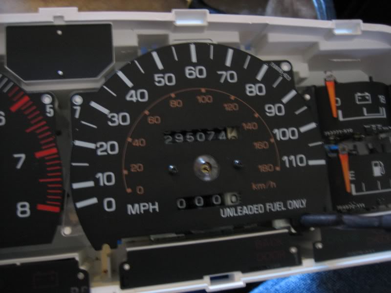
But, as promised, pics of my ATTEMPT to swap the odometer over. The goal was to TRY to keep going with my current actual mileage:
I took the long way with this, and actually pulled the speedometer assembly out of the old cluster I later noticed that you can actually remove just the odometer portion without pulling the entire thing apart
first thing to do would be to remove the gauge's bezel from the cluster housing. this is a pretty easy thing to do; just push the tabs that hold the 2 peiced together, there's 4 across the top and 4 across the bottom:
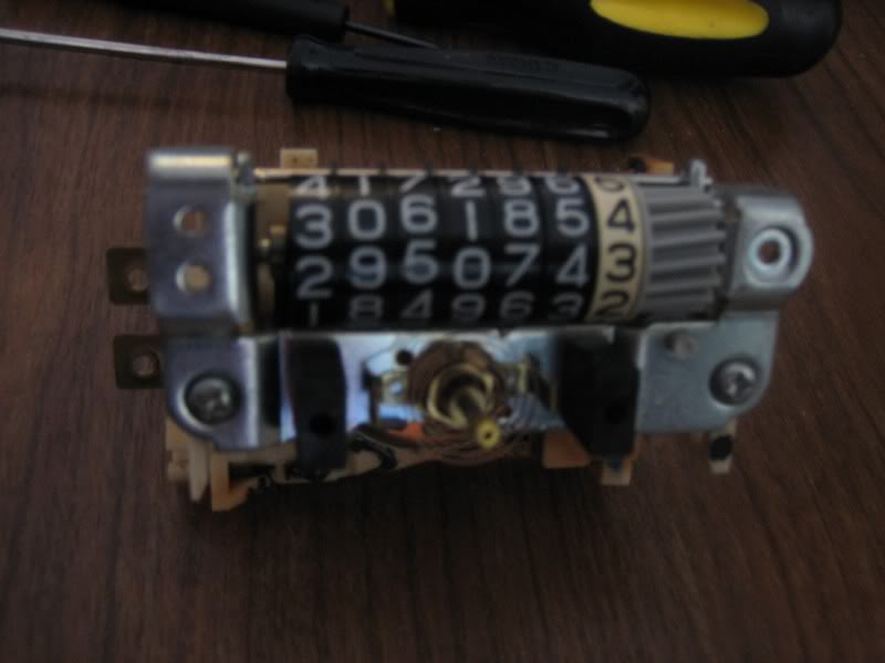
I pulled the screws from the back that holds the speedometer in place:
and just lifter the cluster up, leaving the speedometer assembly lying there:
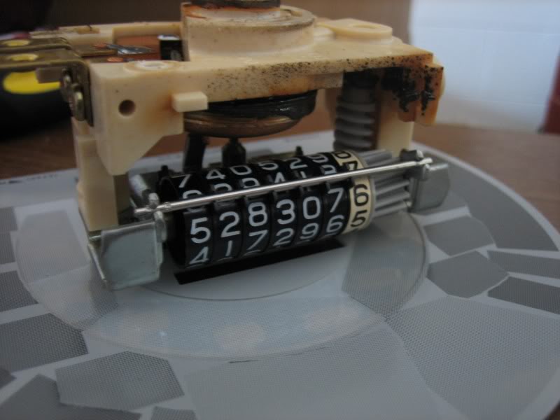
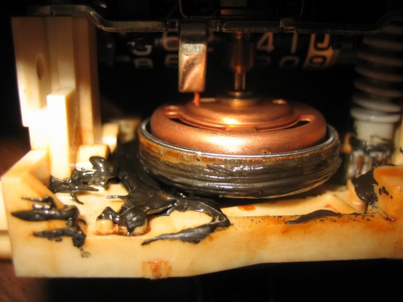
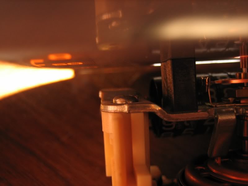
and then got a good look at the grease slug out after 295k miles
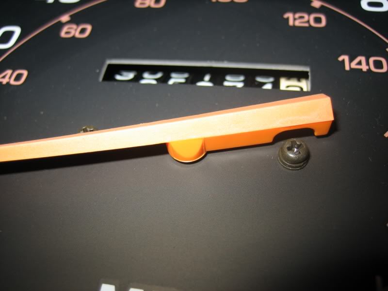
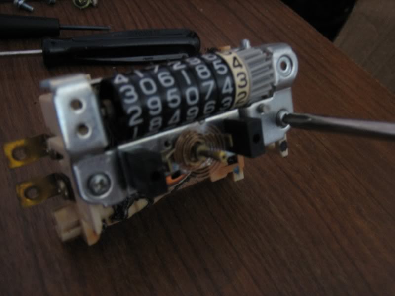
now, the screws that needed getting to were two little ones, conviently placed just behind the gauge face:
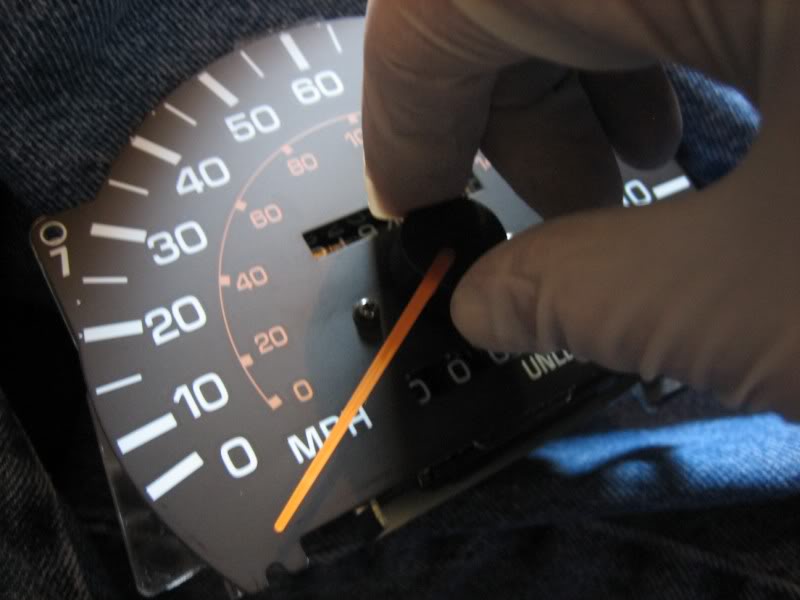
which meant the gauge face had to come off, held in with two little black screws on each side of the needle:
and in order to get the face off, you have to pry off the needle... this is where things went sour
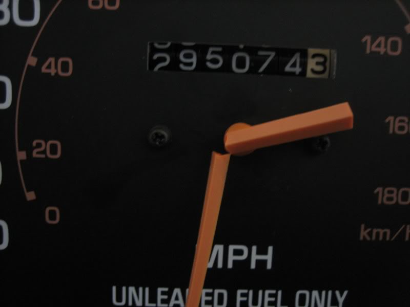
but I really didn't sweat it cause I wouldn't be using that needle in the end anyhow
so I grabbed it with a pair of pliers and ripped what was left off, and continued on
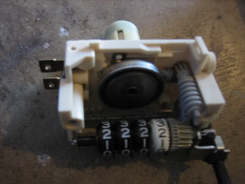
and once the face is pulled off, you're left with the speedometer and odometer assembly
to pull the odometer off, just remove the 2 screws holding it on
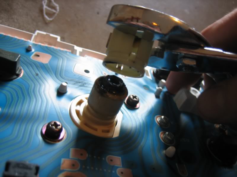
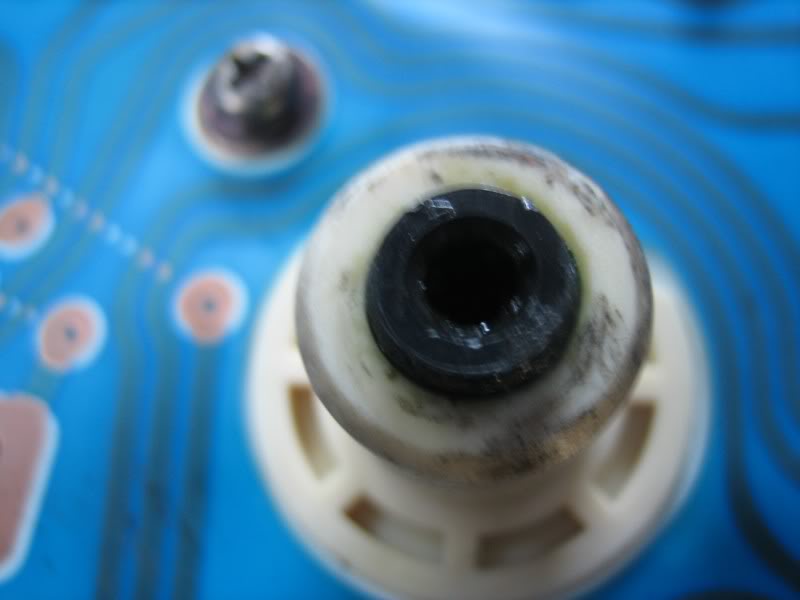
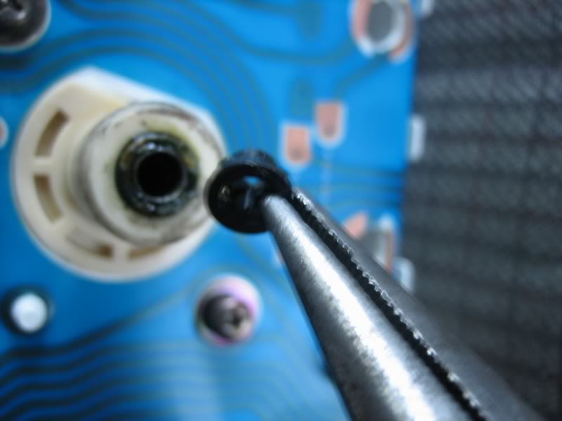
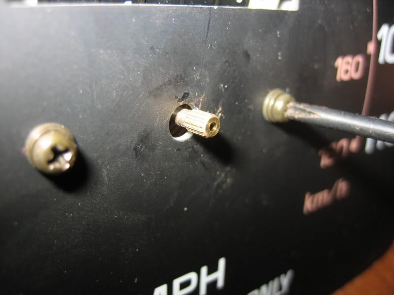
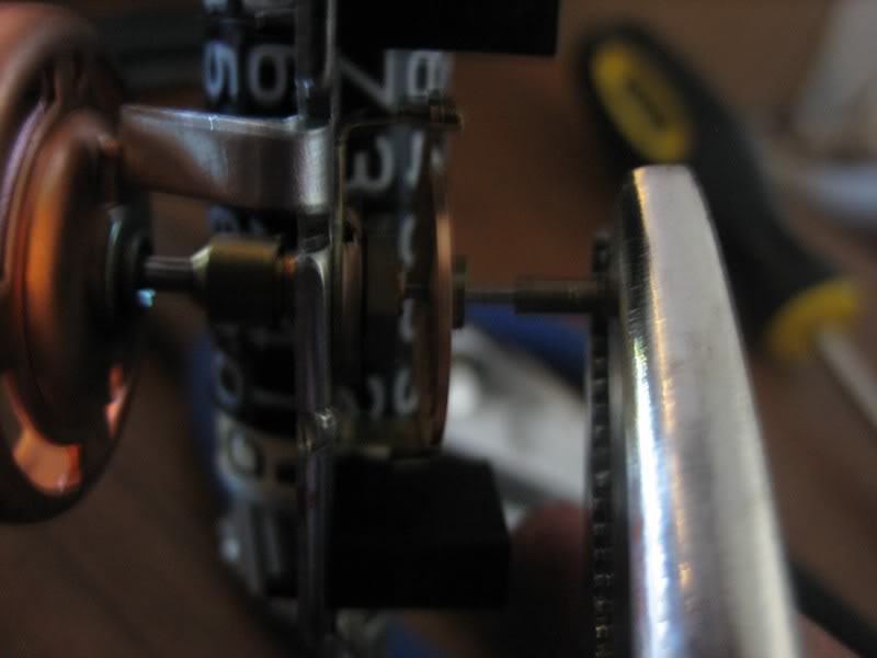
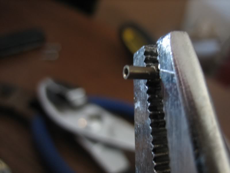
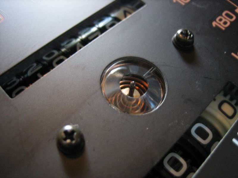
now you might have noticed the little bushing on the end of the pin that the needle pushes onto:
but with a pair of needle-nose vise grips, and some working back and forth, it comes right off, and leaves a bare shaft, wich is ironically exactly what the SR5 cluster's needle uses
and this is all that I would need from the old cluster
the removal of the odometer in the SR5 cluster is the same process, accept for the removal of the needle. remember I mentioned it uses just a bare shaft with no bushing that's pushed onto it; that means the needle and actually be twisted a little. this helps A LOT to get the needle off without breaking it
with some golves on to prevent finger prints, grab the needle with your index finger and thumb, and twist it counter-clockwise while at the same time pulling it up, and it should pull right off
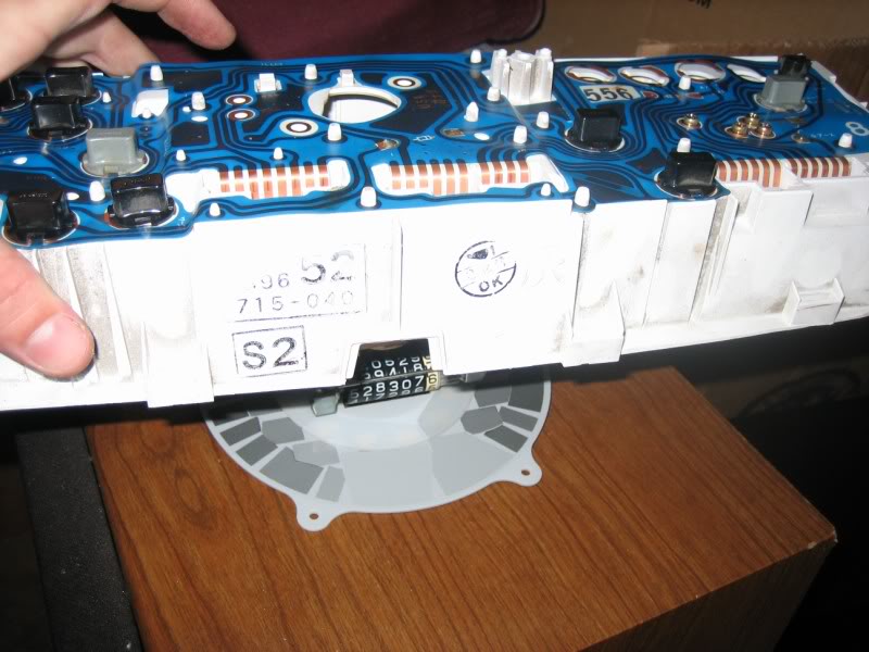
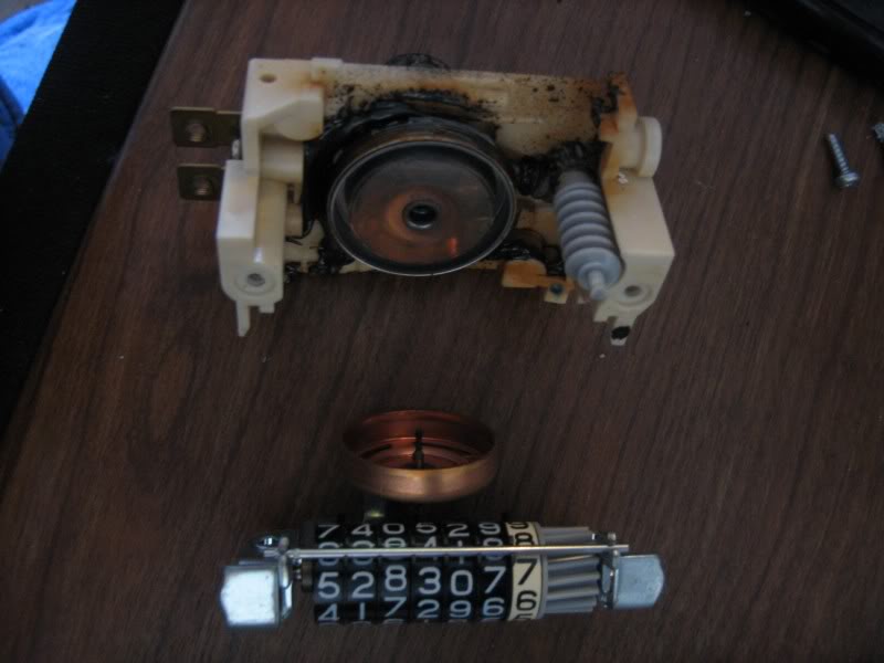
pull the face off the same way, and you're left with the SR5 speedo and odometer assembly
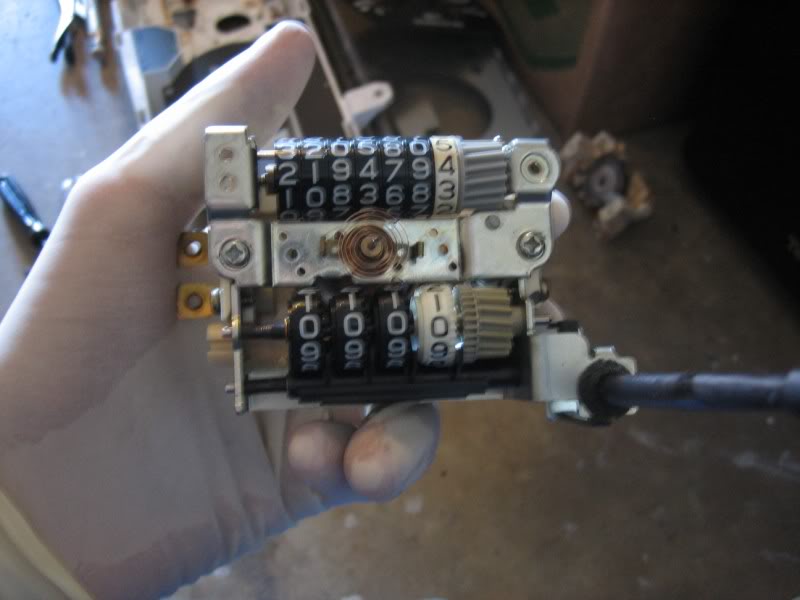
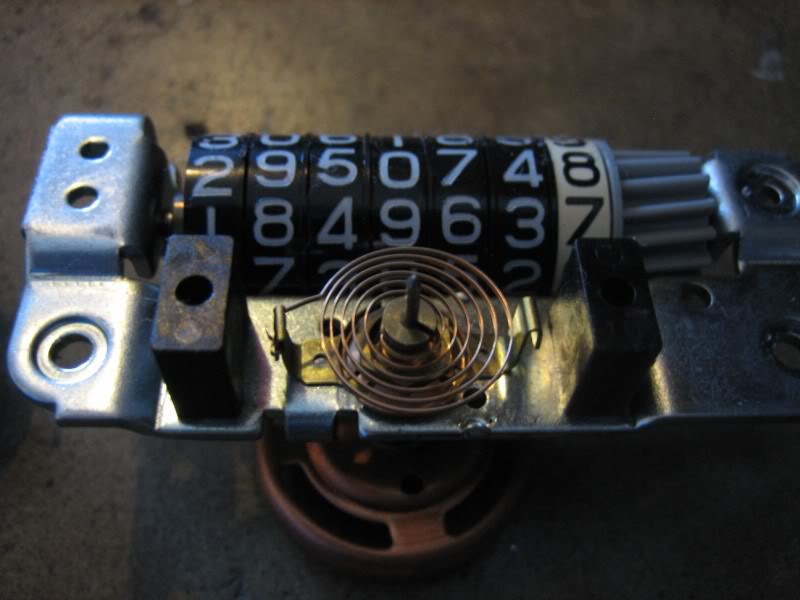
remove the odometer assembly, and you're left with the speedo and mileage trip
and this is main part I wanted to keep
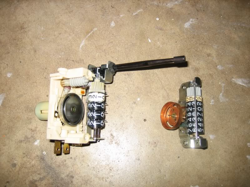
comparing the 2; the one out of the SR5 is on the left, and the one out of my old cluster is on the right.
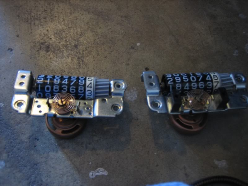
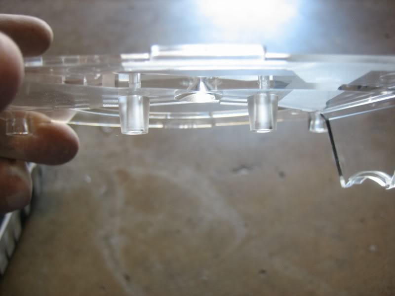
you'll notice the 2 plastic blocks on the old one; those hold the gauge face out. you'll have to pull those off (they just pop right off), cause the SR5 gauge face has risers built into it, because of the way it is back-lit
so with the old odometer install into the SR5 cluster, I pushed onward
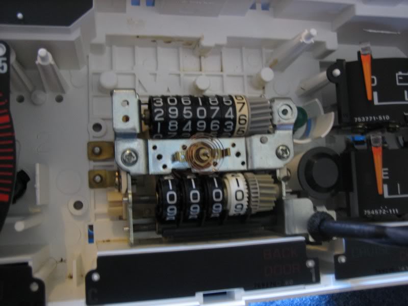
and for a moment, I though this was goint to work out great
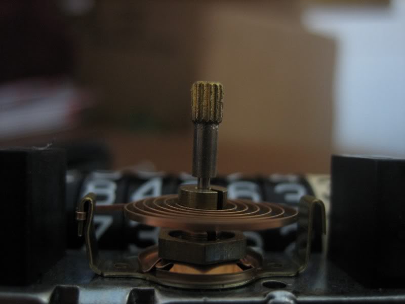
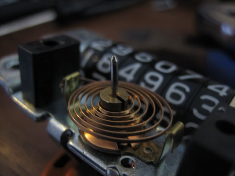
untill I went to push the needle on... and it wouldn't stay at 0...
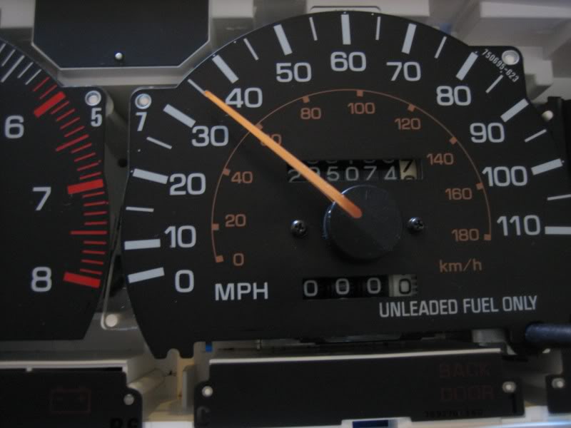
I must have sometime while I was taking the assembly apart, stretched the coiled return spring, so that it didn't want to pull the needle back down. Chances are that after doing that, I ruined the calibration for it too...
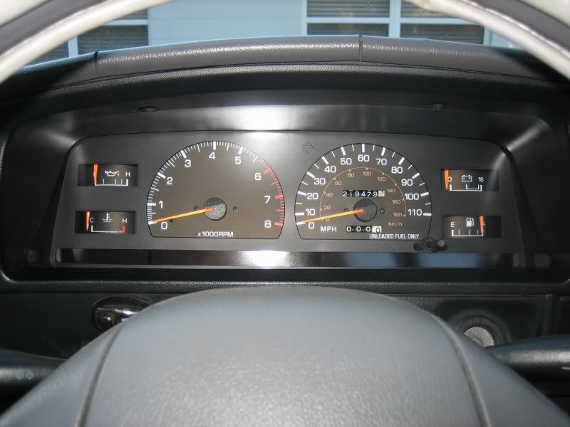
I took EVERYTHING back apart, and put the SR5's odometer back in, and that's what I'm running... so my truck only have 219k on it now but at least it works, and it's still accurate according to my GPS. But I'm going to roll it up to where it's suppose to be when I pull the cluster out tomorrow to install new bulbs. It's a long, slow process, and there's no quick way to roll it up, but it's ok, cause I have a half day at work because of good friday 
the one with the light is essentially an on/off switch, and the one for the actual pressure gauge varies resistance according to the oil pressure. But I'll look at AAP's computer again tomorrow when I go to pick up my replacement (I was going to get it today, but I had to help some family move some furniture )But, as promised, pics of my ATTEMPT to swap the odometer over. The goal was to TRY to keep going with my current actual mileage:
I took the long way with this, and actually pulled the speedometer assembly out of the old cluster
I later noticed that you can actually remove just the odometer portion without pulling the entire thing apart first thing to do would be to remove the gauge's bezel from the cluster housing. this is a pretty easy thing to do; just push the tabs that hold the 2 peiced together, there's 4 across the top and 4 across the bottom:
I pulled the screws from the back that holds the speedometer in place:
and just lifter the cluster up, leaving the speedometer assembly lying there:
and then got a good look at the grease slug out after 295k miles
now, the screws that needed getting to were two little ones, conviently placed just behind the gauge face:
which meant the gauge face had to come off, held in with two little black screws on each side of the needle:
and in order to get the face off, you have to pry off the needle... this is where things went sour
but I really didn't sweat it cause I wouldn't be using that needle in the end anyhow
so I grabbed it with a pair of pliers and ripped what was left off, and continued on
and once the face is pulled off, you're left with the speedometer and odometer assembly
to pull the odometer off, just remove the 2 screws holding it on
now you might have noticed the little bushing on the end of the pin that the needle pushes onto:
but with a pair of needle-nose vise grips, and some working back and forth, it comes right off, and leaves a bare shaft, wich is ironically exactly what the SR5 cluster's needle uses
and this is all that I would need from the old cluster
the removal of the odometer in the SR5 cluster is the same process, accept for the removal of the needle. remember I mentioned it uses just a bare shaft with no bushing that's pushed onto it; that means the needle and actually be twisted a little. this helps A LOT to get the needle off without breaking it
with some golves on to prevent finger prints, grab the needle with your index finger and thumb, and twist it counter-clockwise while at the same time pulling it up, and it should pull right off
pull the face off the same way, and you're left with the SR5 speedo and odometer assembly
remove the odometer assembly, and you're left with the speedo and mileage trip
and this is main part I wanted to keep
comparing the 2; the one out of the SR5 is on the left, and the one out of my old cluster is on the right.
you'll notice the 2 plastic blocks on the old one; those hold the gauge face out. you'll have to pull those off (they just pop right off), cause the SR5 gauge face has risers built into it, because of the way it is back-lit
so with the old odometer install into the SR5 cluster, I pushed onward
and for a moment, I though this was goint to work out great
untill I went to push the needle on... and it wouldn't stay at 0...
I must have sometime while I was taking the assembly apart, stretched the coiled return spring, so that it didn't want to pull the needle back down. Chances are that after doing that, I ruined the calibration for it too...
I took EVERYTHING back apart, and put the SR5's odometer back in, and that's what I'm running... so my truck only have 219k on it now
but at least it works, and it's still accurate according to my GPS. But I'm going to roll it up to where it's suppose to be when I pull the cluster out tomorrow to install new bulbs. It's a long, slow process, and there's no quick way to roll it up, but it's ok, cause I have a half day at work because of good friday
Last edited by iamsuperbleeder; Apr 9, 2009 at 08:09 PM.


