
ChetcoJoe's 1990 4Runner Build-up Thread
 Jan 24, 2012 | 04:04 PM
#1

Thread Starter
Registered User
Joined: Jan 2012
Posts: 5
Likes: 0
From: Southern Oregon
ChetcoJoe's 1990 4Runner Build-up Thread
Back in 2009 I picked up a 1990 Toyota 4Runner salvage vehicle to use as donor parts for my 1994 model.
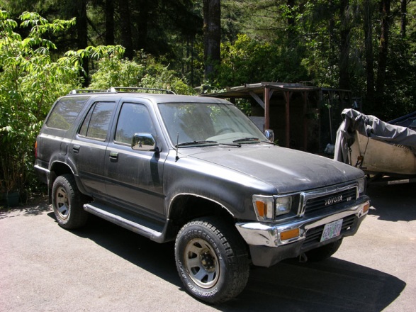
The engine has blown and brakes rusted shut from sitting too long but the body and interior were still in
good shape.
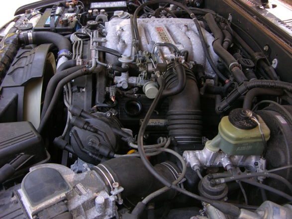
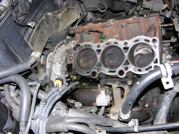
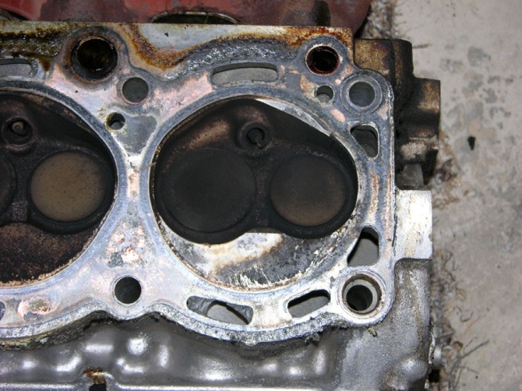
I brought it home on a car carrier and parked in the back yard and there it sat. After a while I got the idea I might try to restore it to working order so I got a lift and pulled the engine. After tearing it down I discovered the problem was a bad rod bearing caused the Piston to actually hit the head at the top of the compression stroke. Simple enough, just rebuild the engine.
I next proceeded to tear it down, bag the parts and put them on the shelf. Using plastic storage bags and
makers, I tried to label everything as well as possible as I bagged them. It would have really helped if I
had taken a lot more pictures of the tear down as I could have used them later.
Over the next two years (yes really) I took various components down to the machine shop to have them worked on. First the block which was cleaned and checked for cracks, re-bored and deck resurfaced. The crankshaft was trash (from bad rod) so a new one there. The heads were reworked and valves redone, lifters shimmed, seals installed. New pistons, rings, bearings, gaskets, and such purchased. As each item
was reworked they were placed back on the shelf till I finally had them all done.
The in the fall of 2011, I was ready to try to put it all back together. I planned to use the vehicle as a test bed for a new digital gauge system (vGauge) my company makes so I was going to install additional
sensors on the engine during the rebuild. The plan was to add dual Exhaust Gas probes, block coolant temp, fuel pressure, and Transmission fluid temp. In addition, all the other standard gauges would be converted over to the digital format such as Engine temp, Oil PSI, Fuel Level, Volts, and so on. The
vGauge also is able to interface with the MAP/Air Flow sensor and O2 sensors so we see those readings as well.
This thread will cover the rebuild of the engine, adding the sensors, and installation and configuration of
the Digital gauge system.
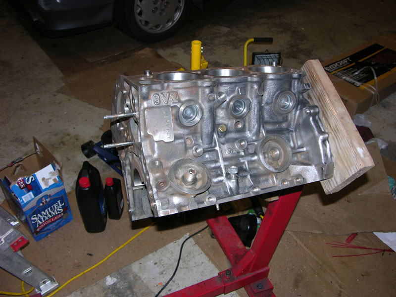
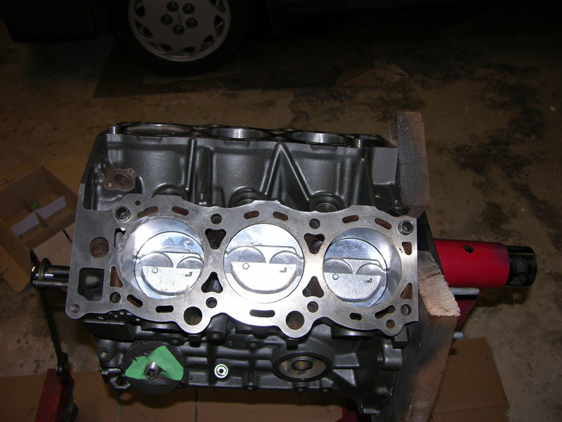
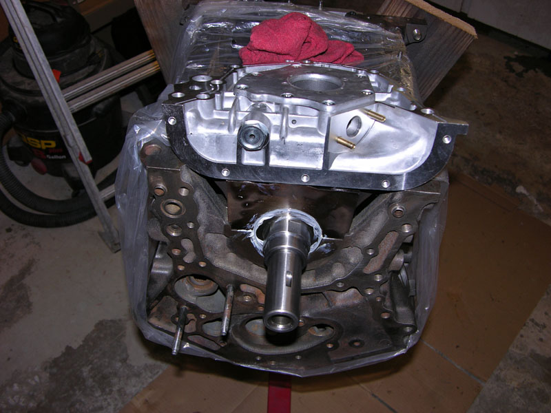
11/3/2011 � Fresh block ready for paint � Tanked and bored and decked by machine shop
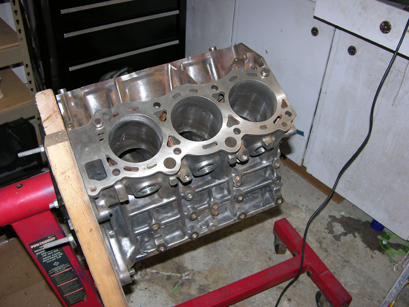
11/3/2011 - Over bored to fit new larger pistons
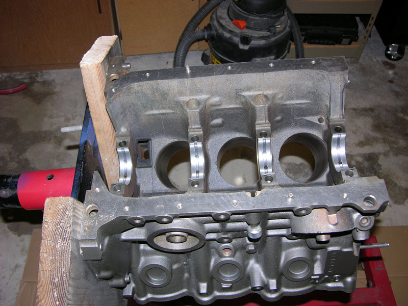
11/7/2011 � Painted and ready for new crankshaft. Main bearings in place
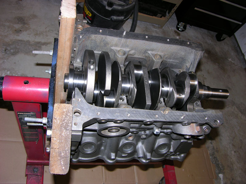
11/7/2011 � Crank in place
11/7/2011 � plastigauge check that clearances are correct.
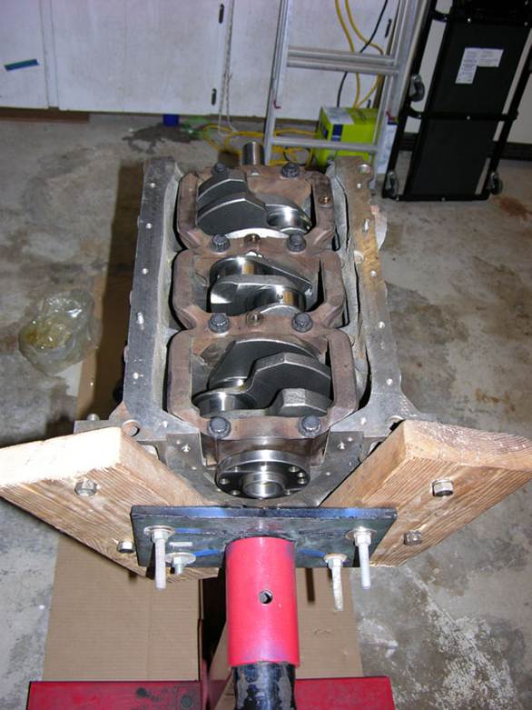
11/7/2011 � Crank cap installed and torqued � do not forget the assembly lube
11/9/2011 � Pistons installed. Seems the rings can face up or down?
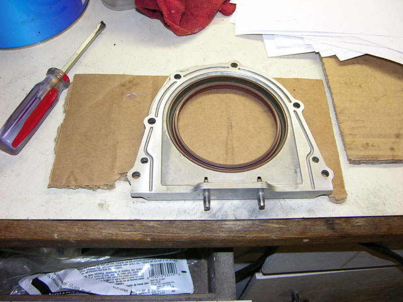
11/10/2011 � Rear main Oil seal prep work
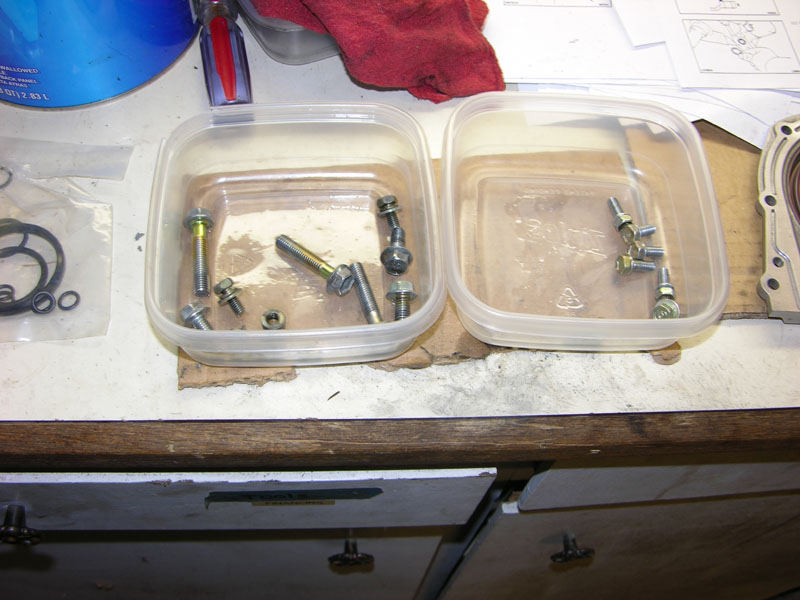
11/10/2011 � cleaned up bolts for rear main seal
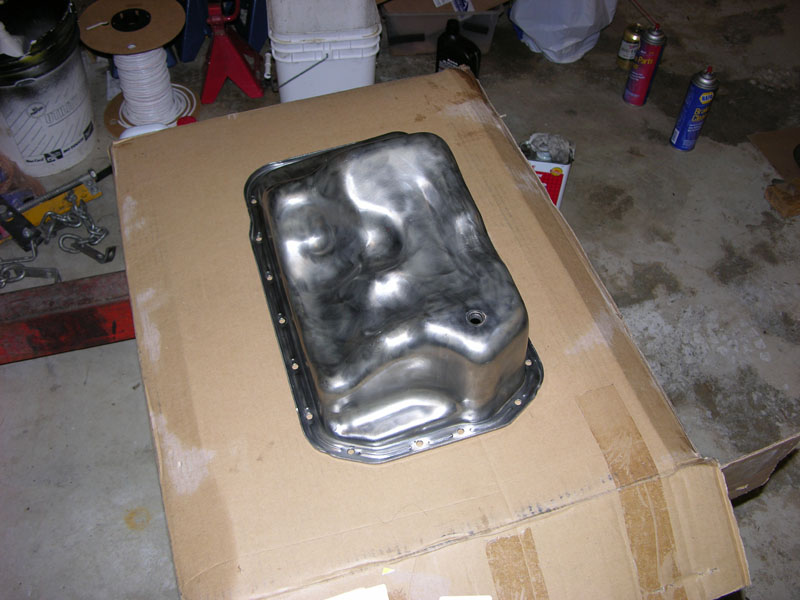
1/10/2011 � Oil Pan prep for paint
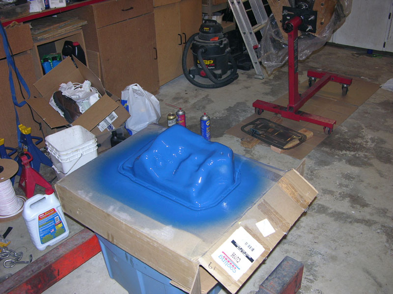
11/10/2011 � Painted Oil Pan
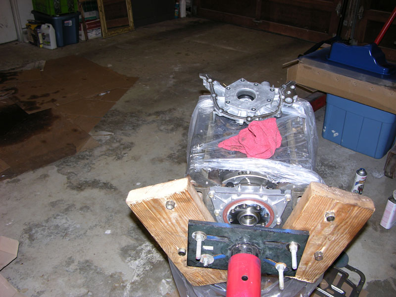
11/10/2011 � Rear Main Oil seal in place
11/10/2011 � New Oil pump to be installed
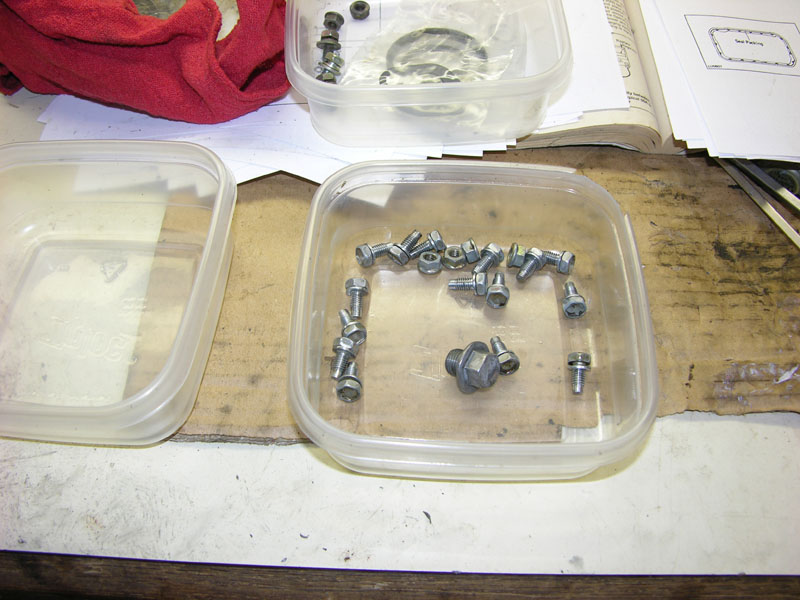
11/11/2011 � Cleaned up Oil Pan Bolts
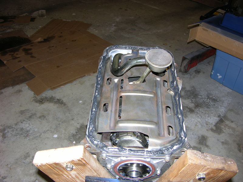
11/11/2011 � Baffle and Oil Pickup installed. �The Right Stuff� for the pan seal
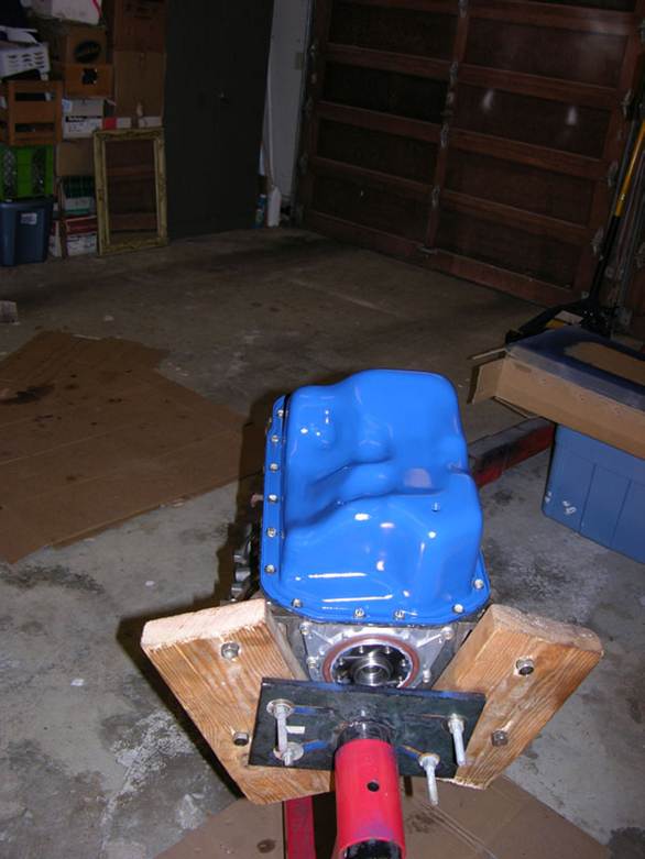
11/11/2011 � Oil Pan bolted down
11/13/2011 � Water and Oil pumps installed. Knock sensor installed with new cable.
11/13/2011 � 11/27/2011 Camera failure
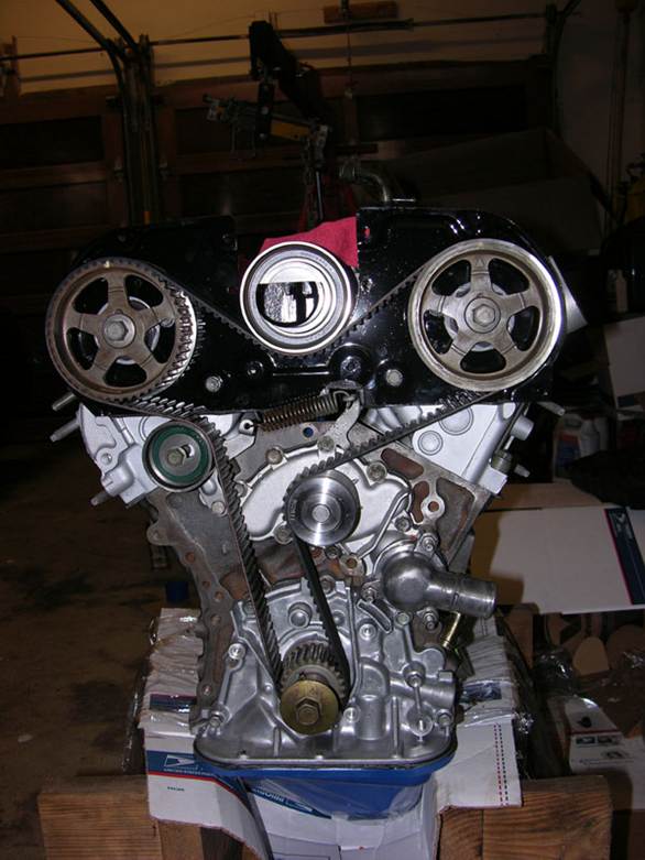
11/27/2011 � Installed timing belt and tensioner
12/5/2011 -Timing Belt and Idler Pulley installed. Fan Bracket temporally placed till I find the rest of the
bolts
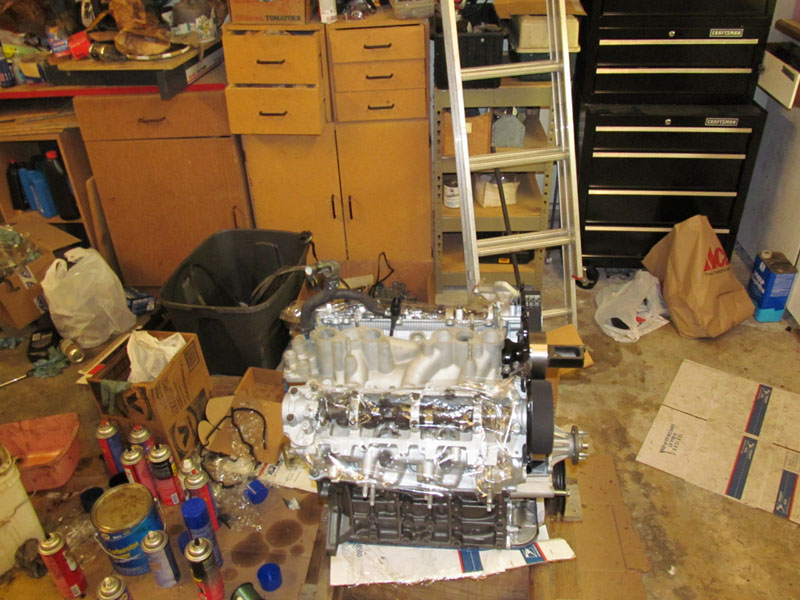
12/5/2011 -Air Intake Manifold placed and bolted
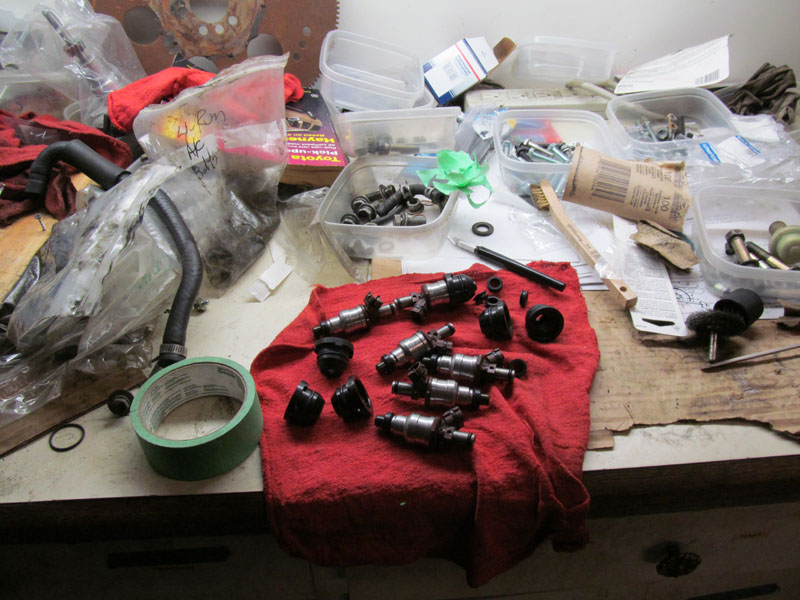
12/5/2011 - Cleaned fuel injectors. All new O rings but reused inserts since they looked fine
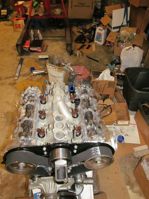
12/5/2011 - Fitted Fuel Injectors without fuel rails
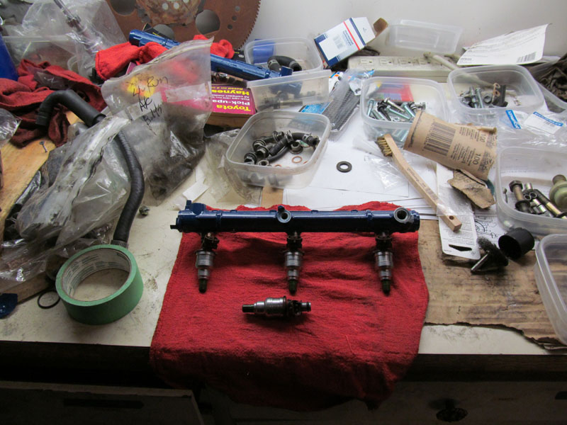
12/5/2011 � Typical Fuel Rail setup
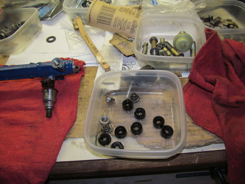
12/5/2011 - Spacers and nuts
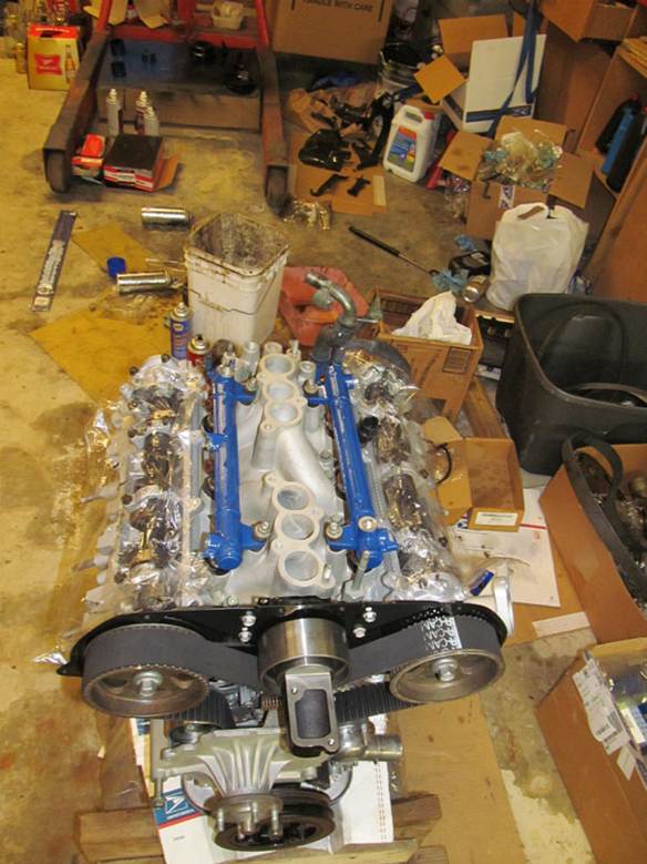
12/5/2011 � Fuel Rails in place
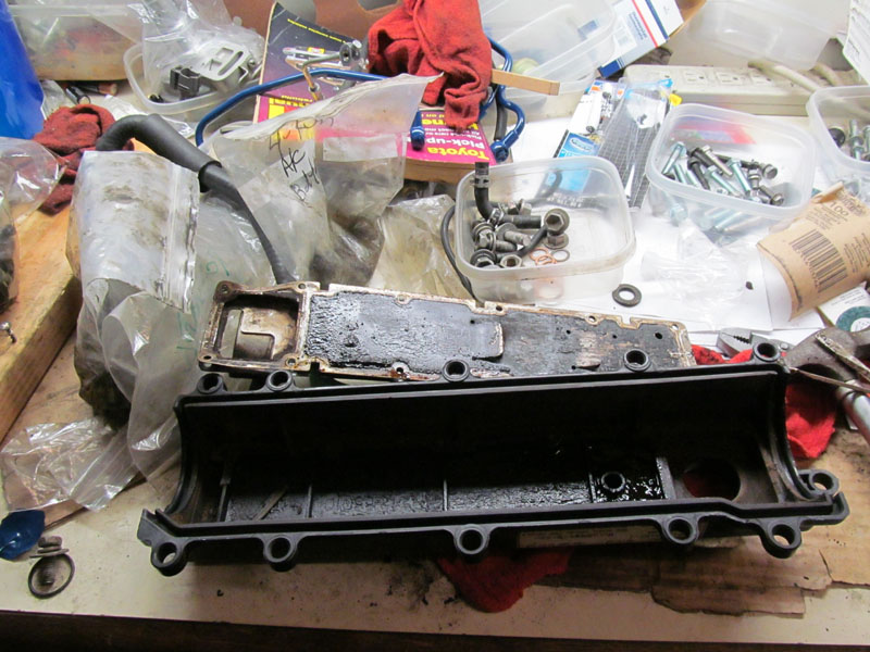
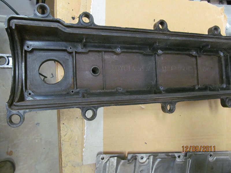
12/6/2011 � Disassembled Valve covers to be cleaned. Had to grind off rivets on Oil disperser to remove
them for cleaning. With all this sludge, it would ruin a brand new engine in minutes.
12/6/2011 � Rear of block with view of rear main seal and heater pipe
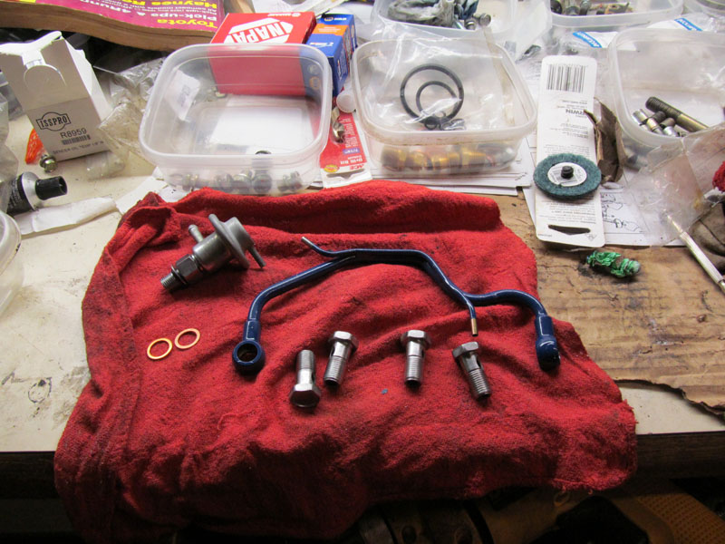
12/7/2011 � Cleaned and painted Fuel Rail Crossover pipe and bolts
12/8/2011 � Cleaned up Valve covers before reassembly. Took 4 hours and 3 cans of brake cleaner and a
bottle of Super Clean. This stuff really works!
12/9/2011 � Drilled and tapped holes to remount the oil baffles. Used #6-28 thread an 3/8� machine SS
bolts
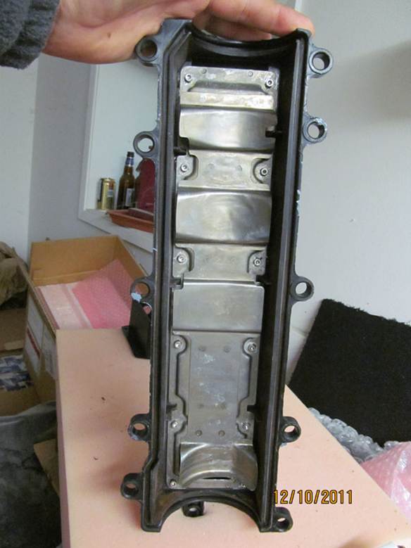
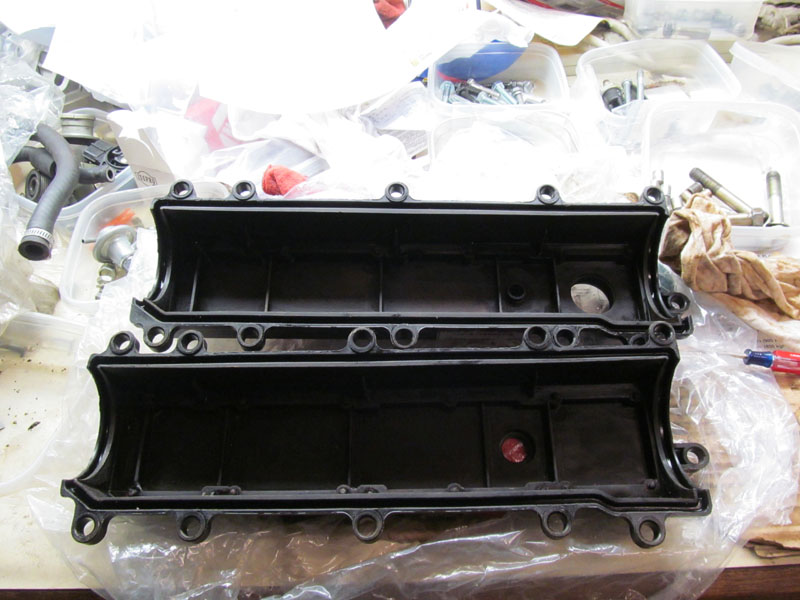
12/10/2011 � Re-installed Oil baffles in valve covers � look good as new and only took 4 days. But if they
were not clean, the whole job would have been wasted
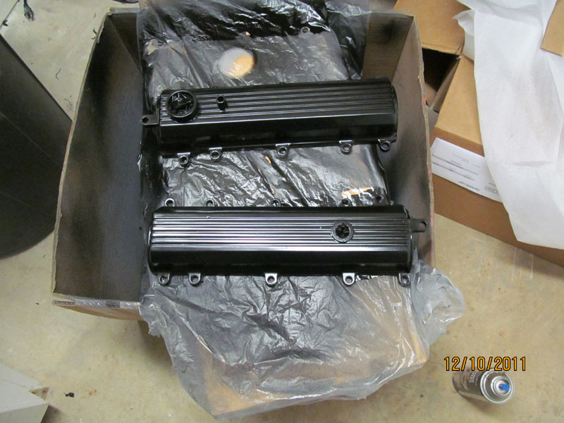
12/10/2011 � Painted Valve Covers
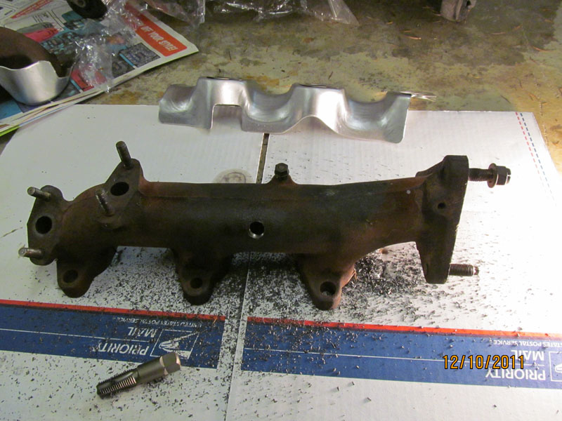
12/10/2011 � Tapped Exhaust manifold to accept adjustable EGT probe (one on each head) Used a 3/5�
tap
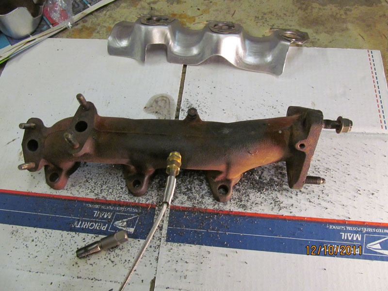
12/10/2011 � fitted EGT probe. Can be adjusted latter. EGT probes measure up to 1600F and are very
responsive to engine load.
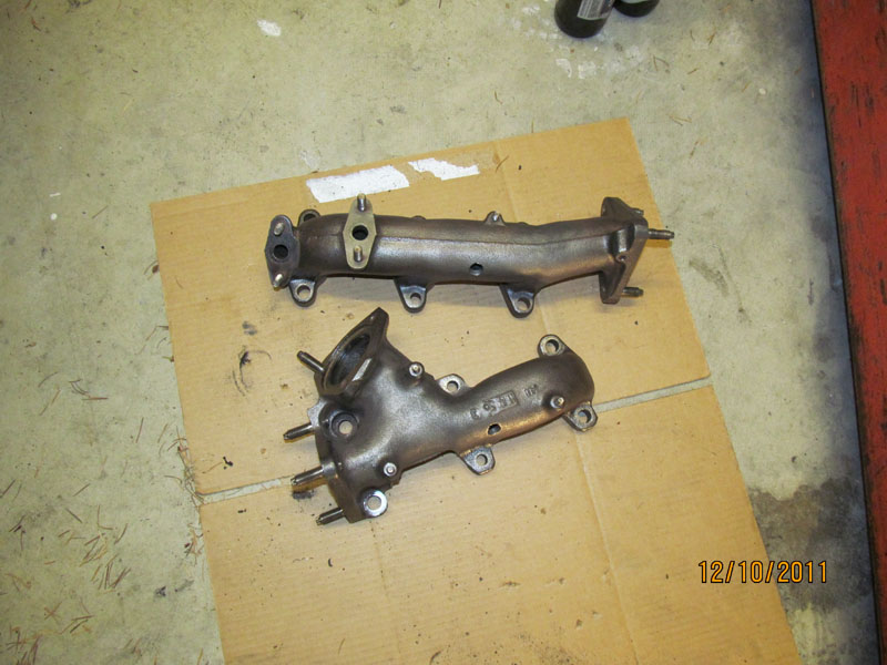
12/10/2011 � Cleaned and wire brushed exhaust manifolds before painting. Almost hate to paint them.
Used a 1500F header paint that I had used in the past and works well
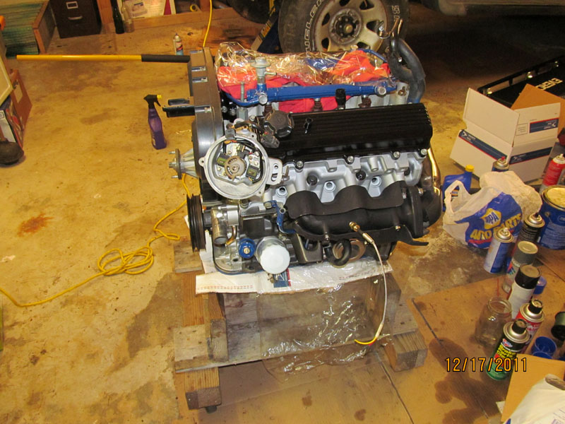
12/17/2011 � Mounted Exhaust Manifolds and heat shields. New EGT probe in place, Made sure the
location would not interfere with anything else in the chassis.
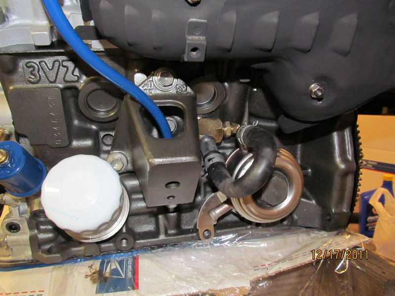
12/17/2011 � Installed a 400F water temp sender before the Oil cooler. This will let us know the core
block water temp. Would have been good to install one on the outlet side of the cooler to be sure it was
doing anything (drop in temperature). Note Blue Oil Pressure sender on the left.
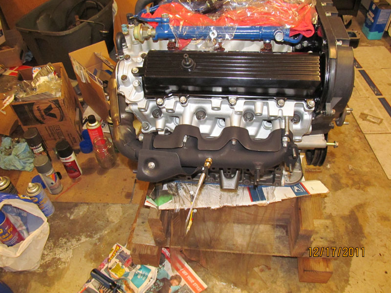
12/17/2011 � view of the passenger side Exhaust setup wit crossover tube installed. Much easier to do it
now then after the engine is in the truck
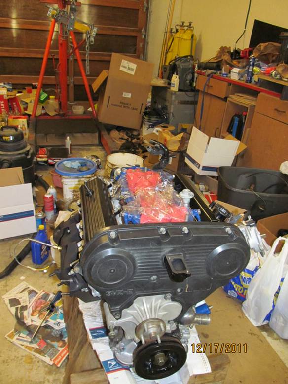
12/17/2011 - Finished putting on the Timing Cover after I was convinced the timing was correct. Put a
long screw driver in the number 1 cylinder hole and rotated crank till it topped out and mark on crank
pulley was at 0. Also checked that I had compression there at the same time by feeling for air escape.
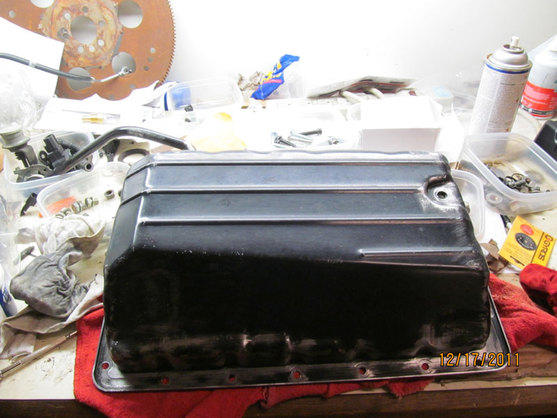
12/17/2011 � Drained the Automatic transmission fluid and pulled the pan to change the filter. Prepped
and ready for paint
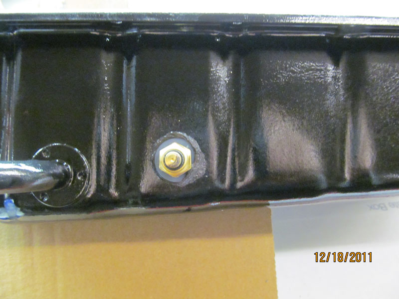
12/18/2011 � Drilled and tapped a 1/8� NPT hole to install a 400F temp sender in the Tran Fluid pan.
Made sure it was not going to get in the way inside. Also put backing nut on the inside since the pan
walls were kind of thin.
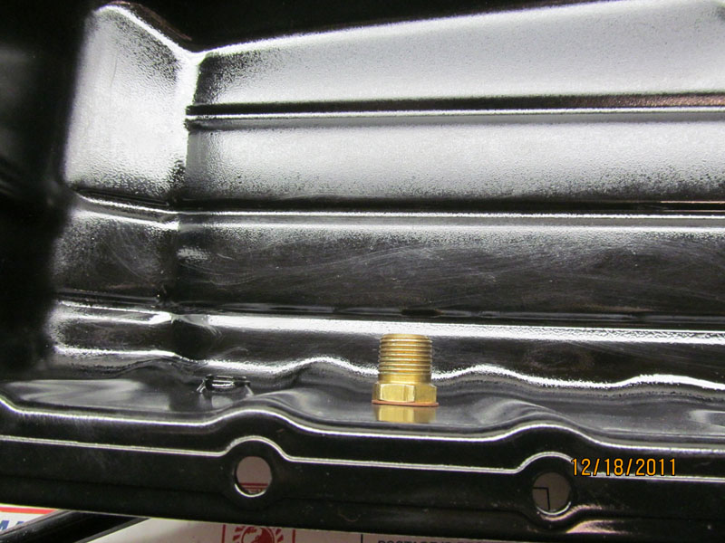
12/18/2011 � Backing nut on inside of tran fluid pan. Really a 1/8� NPT to 3/8� NPT reducer.
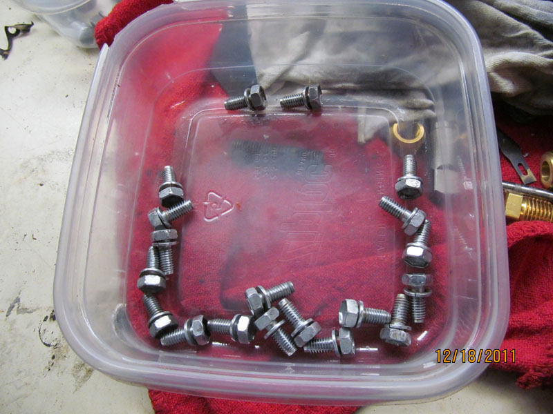
12/18/2011 � cleaned up tran pan bolts
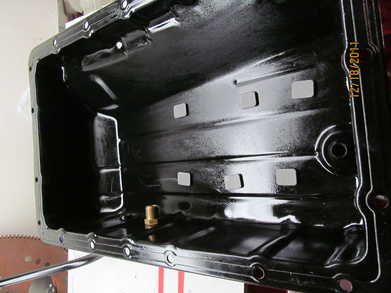
12/18/2011 � Cleaned up magnets replaced in bottom of pan before rebolting to transmission. Applied
RTV to pan seal and on transmission. Most bolts go in OK with long extension but 3 of them are directly
under one of the support members and have to be started by hand and finished off with a wrench.
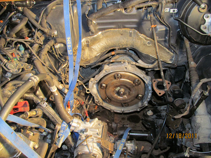
12/18/2011 � Torque converter in place after a quart of tran fluid being added. Was told it clicks in 3
times after being rotated but really only heard 2 clicks. Measured gap with straight and thought I was
right � but wait.
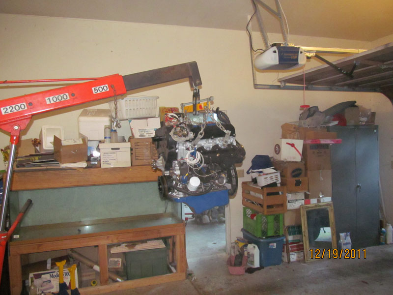
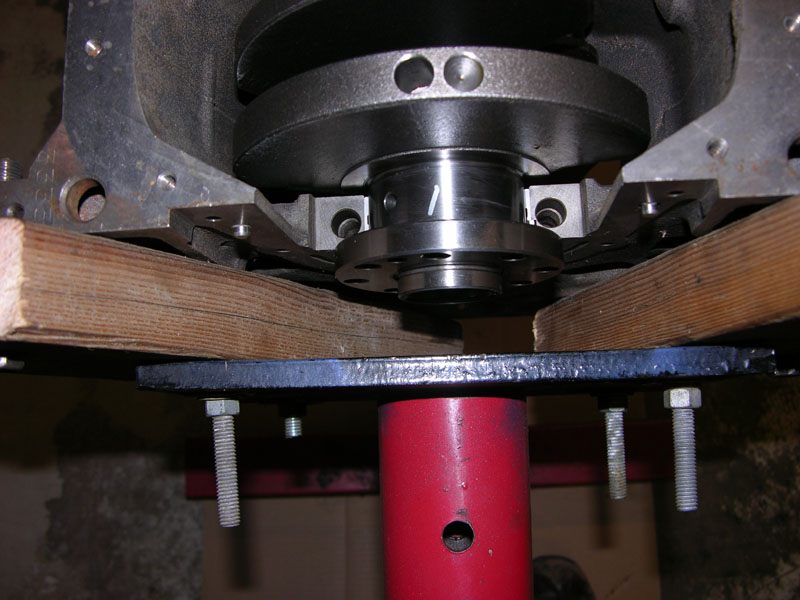
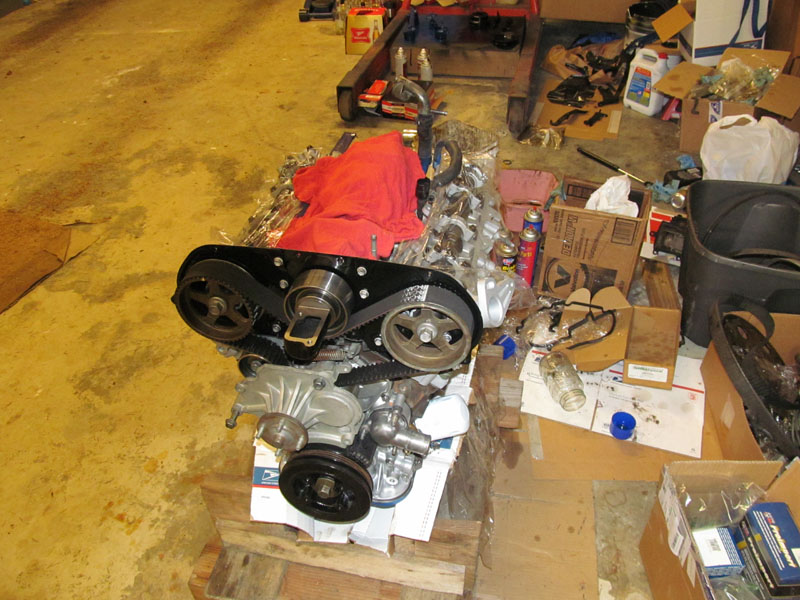
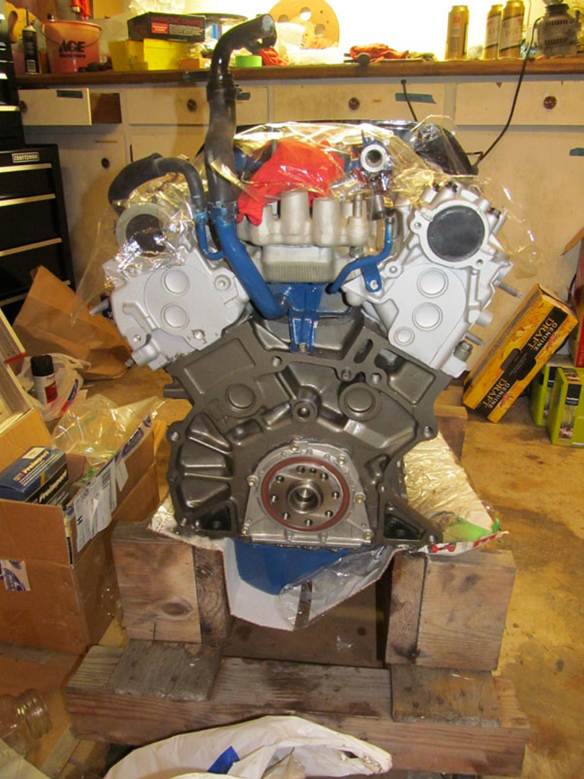
12/19/2011 � Engine up on lift waiting for truck
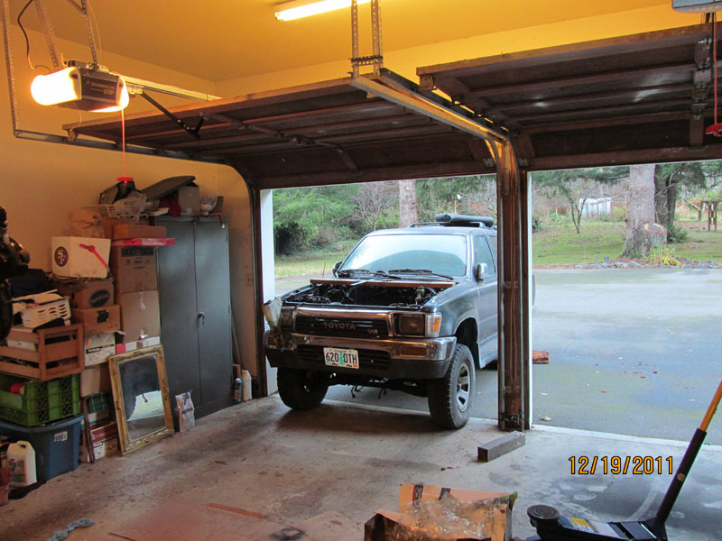
12/19/2011 - Truck being rolled in waiting for engine
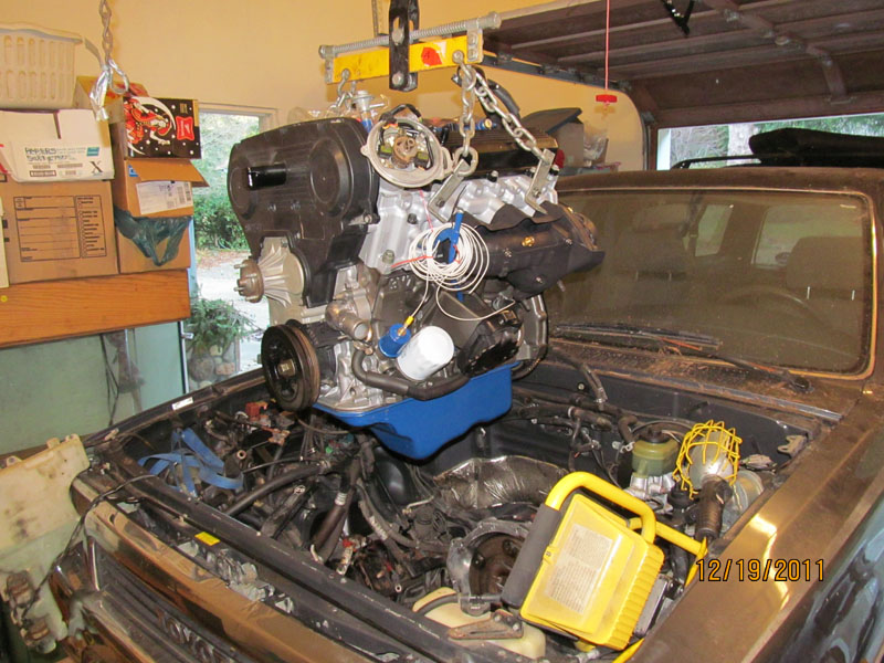
12/19/2011 - Engine going in for first time. Lift had rollers so it was easy to move into place and slide
truck underneath and tilt engine to clear front axel.
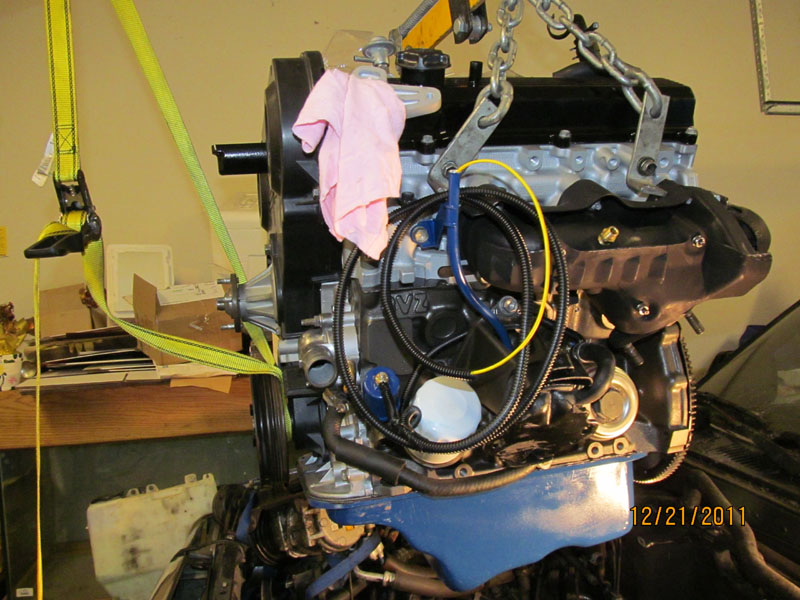
12/21/2011 � Engine coming out of truck. But wait. It was just put in?? Well, after hours of trying, I
simply could not get the engine to bolt up to the transmission. I determined with much frustration, the
torque converter was not pushed in all the way and preventing the flex plate from seating properly. SO
out it comes
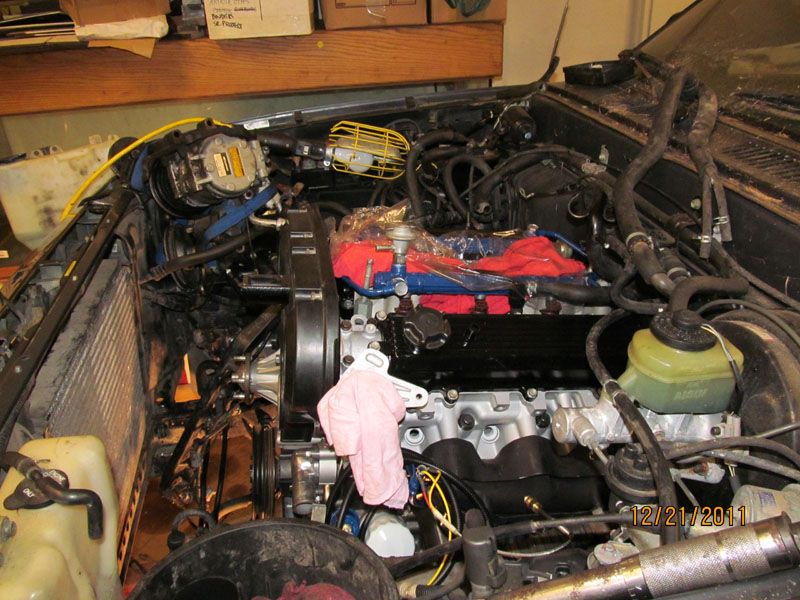
12/21/2011 � After playing around with the torque converter, I get it to snap in some more and now
have the clearance to drop the engine back in and bolt up to transmission. The problem is that the
clearance spec given in the manuals is after the torque converter is pulled back out to the flex plate, It
should be a good 2.5� FROM THE LIP OF THE Bell housing if properly seated all the way and then pulled
forward to the specified 1� after the engine is in.
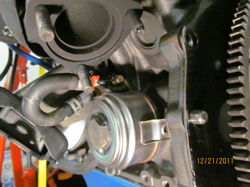
12/21/2011 � Good view of the temperature probe on the Oil Cooler with Sense wire out to harness
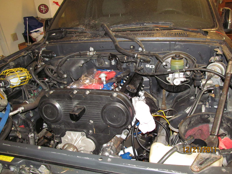
12/21/2011 � Engine finally in � just in time for Christmas!. Found I had to undo the single bolt motor
mount from the chassis bracket in order to move the engine to get it to seat correctly. I had wanted to
avoid this as it very difficult to put the mount nut back in once the engine is in place. However, you can
reach in with a socket and barely get one click on the ratchet and slowly get that nut tightened down. I
do not see how anyone can do it with a torque wrench.
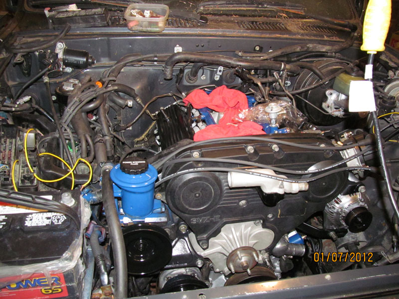
1/7/2012 � Installing Spark wires and distributor
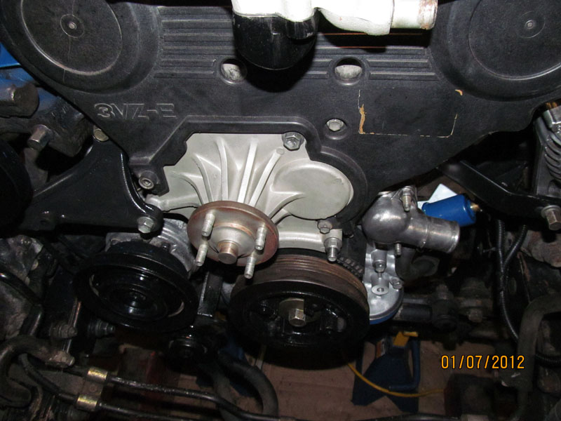
1/7/2011 � Final bolt-down of Fan bracket and PS pump bracket. Note the order of the Power Steer
mount. First Pump then tensioner bracket. Be sure the Engine lift bracket is installed first as everything
else goes on top. I had to redo this 3 times.
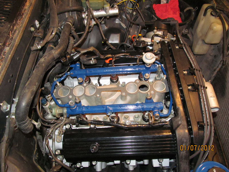
1/7/2011 � Ready for Intake Air chamber. All Fuel rail crossover pipes and pressure relief valve are in
placed and tighten down. I was going to do a fuel pressure test but have a missing cold start injector and
fuel filter to install first
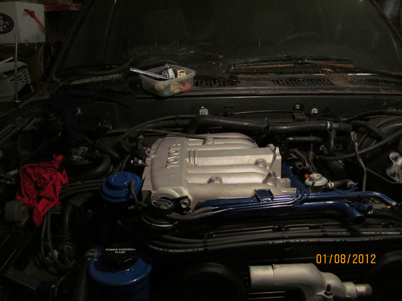
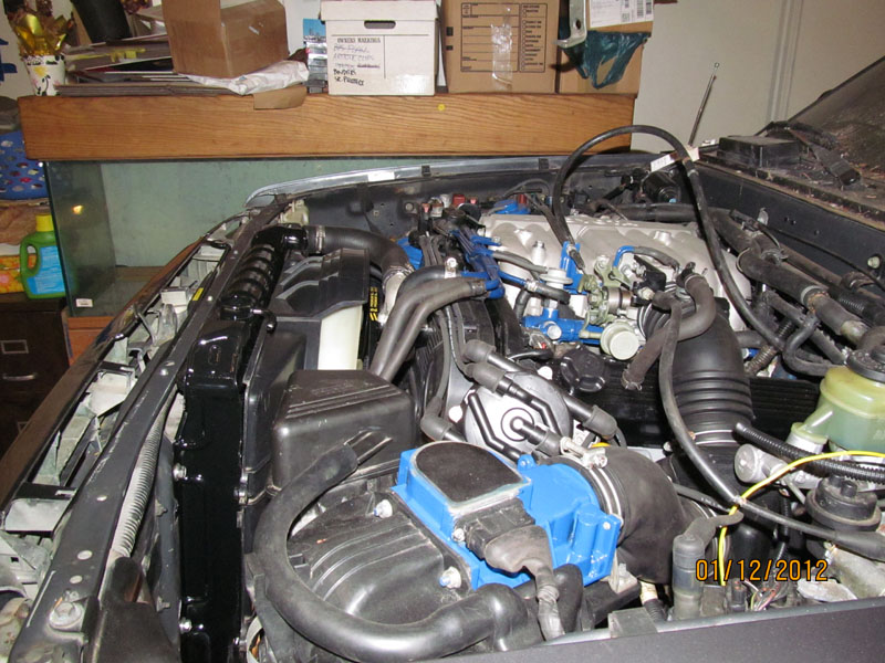
1/8/2012 � Air Chamber on for the first time � took about 3 times to get it right. Be sure to run the Cold
start injector fuel line and wire harness out first before bolting this thing down our you will be doing it
again. Also get the PVC hose on first. You will probably need a new one which I found out after putting
the Air Chamber on the second time.
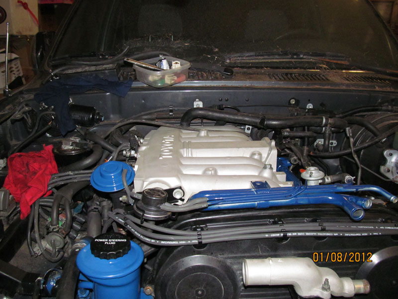
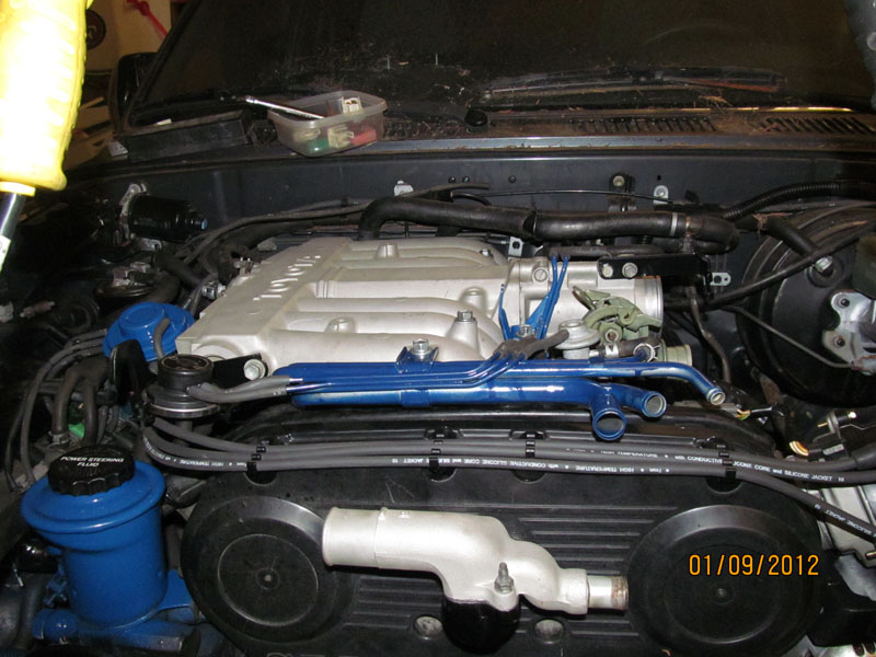
1/8/2012 � Finally got all the Water hose and Vacuum line on. Not too hard as everything was cut to fit.
Had to replace the vac lines to the power steering as that were too brittle with age. I RTV all my water
hoses before I slip them back on and clamp. Never had a leak yet. Be sure to clean the insides out with
rag and screw driver soaked in Brake cleaner. Seem to work well to get a good seal.
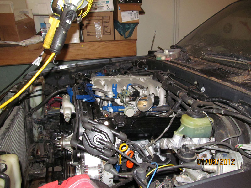
1/9/2012 � Air valve installed.
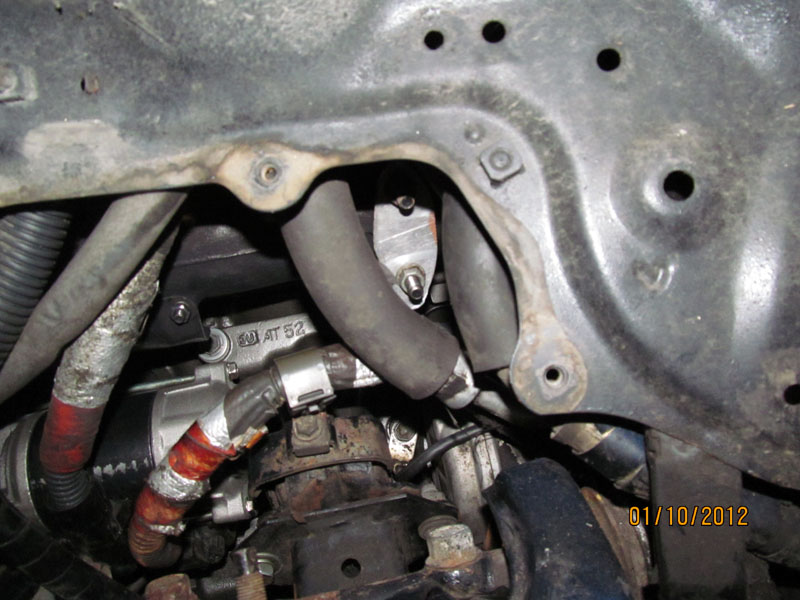
1/9/2012 � Front view for vacuum lines
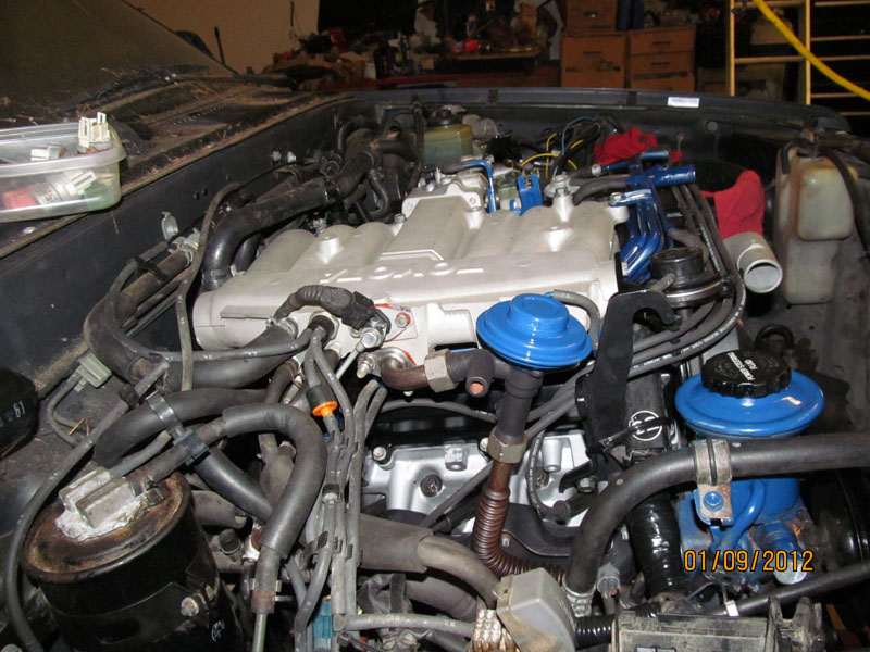
1/9/2012 � passenger side view of vacuum lines and hoses
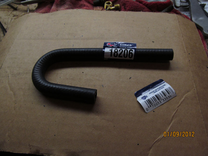
1/9/2012 � New PVC hose from CARQUEST. Maybe not designed for this purpose but works just fine.
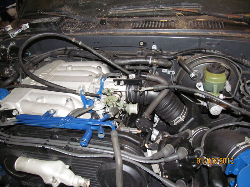
1/10/2012 � Throttle Cables and air ducts in place. All cleaned up with Super Clean � my third bottle.
1/10/2012 � My bypass of Pulsed Secondary Air Induction system that routes filtered air into the
exhaust for some sort of smog reduction � Don�t need it so I machined a block off plate
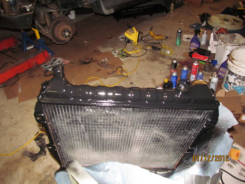
1/12/2012 � Cleaned and painted radiator � Really wish I had done a flow test first to make sure some
critter did not make a nest inside after 2 years sitting outside.
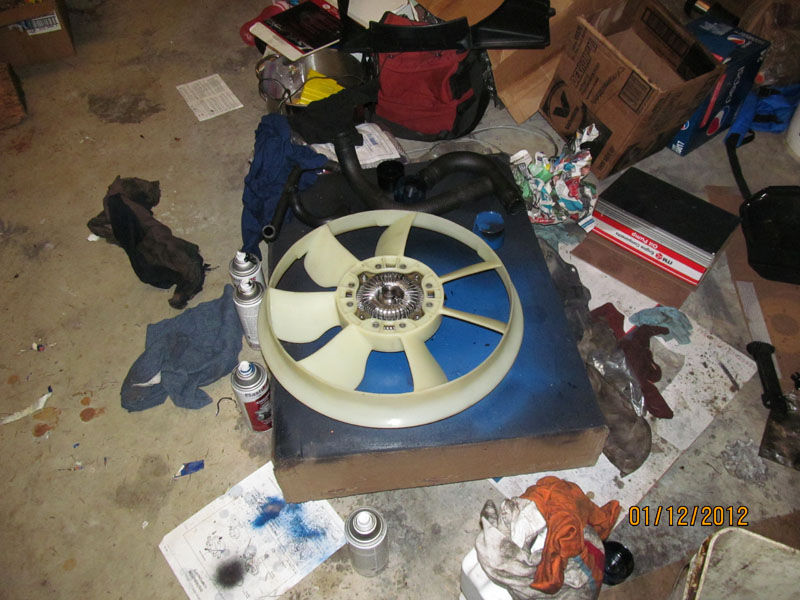
1/12/2012 � Cleaned up fan and hoses. Yea for Super Clean.
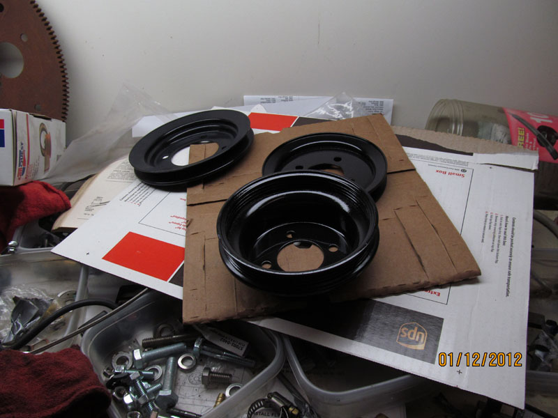
1/12/2012 � Painted belt pulleys
1/12/2012 � Installed Radiator, belts, and pulleys. RTV all the hoses
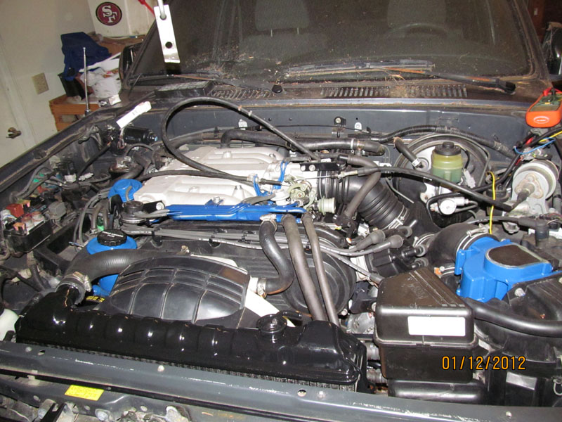
1/12/2012 � Ready to start � With Replaced Fuel Filter and drained fuel tank I was able to purge the fuel
line using the bypass diagnostic connector . Looked for leaks in fuel line and was convinced I was ready
to do a dry run. Put key in � turned it over and it cranked a few times. Let rest a second for fuel to
atomize and tried again � there it goes! Ran for second and I shut it down. Now add water to radiator.
Takes a while to trickle in but eventually get 2 gallons in and time to start again. A few more cranks and
off it goes. Have to keep peddle down slightly for a moment but eventually it holds idle by itself and we
have a running engine. Open up heater and let it run.
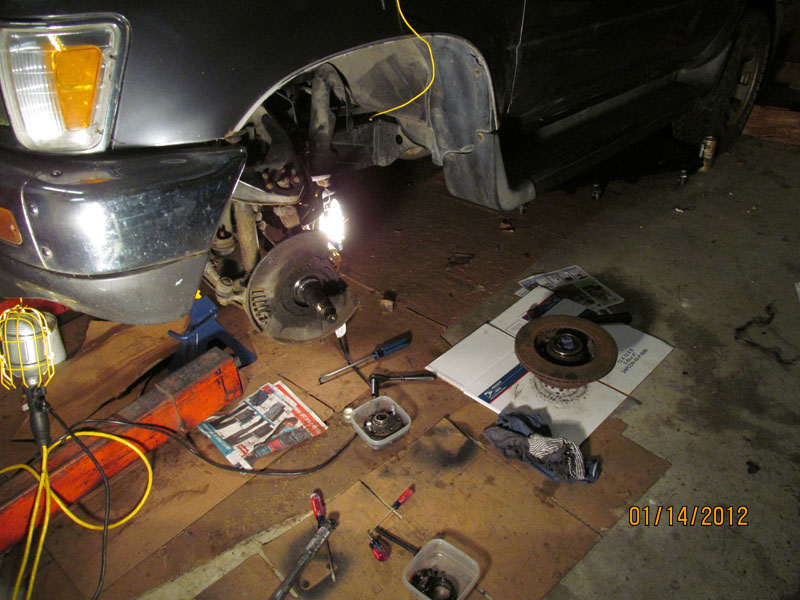
Now I need some brakes.
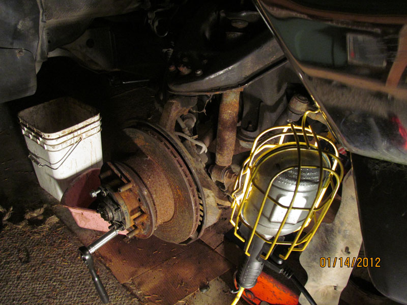
1/14/2012 � Both front brakes were really bad shape. Rotors and calipers were rusted so bad the wheels
would not spin at all. I found new Rotors for $34/ea at RockAuto.com (Christmas gift) and calipers at
Napa Auto for $45/ea so off with the old and on with the new.
1/14/2012 � While doing the rotors and calipers, I also got new wheel bearings since that had to come
out anyway
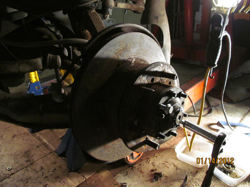
1/14/2102 � nice trick in pulling hub cover plate is undoing the six nuts and threading a 12 mm bolts
back in to pry off the cap � works really well
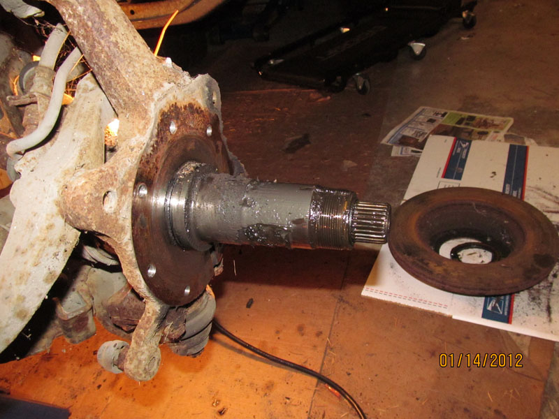
1/14/2012 � Found water in bearings � why am I not surprised!. Anyway the races looked fine with no
rust or pitting so I can just install new bearings.
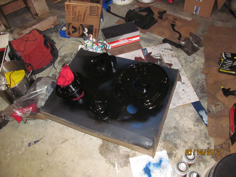
1/14/2012 � Painted up brake parts �Again, spend more time cleaning the assembly.
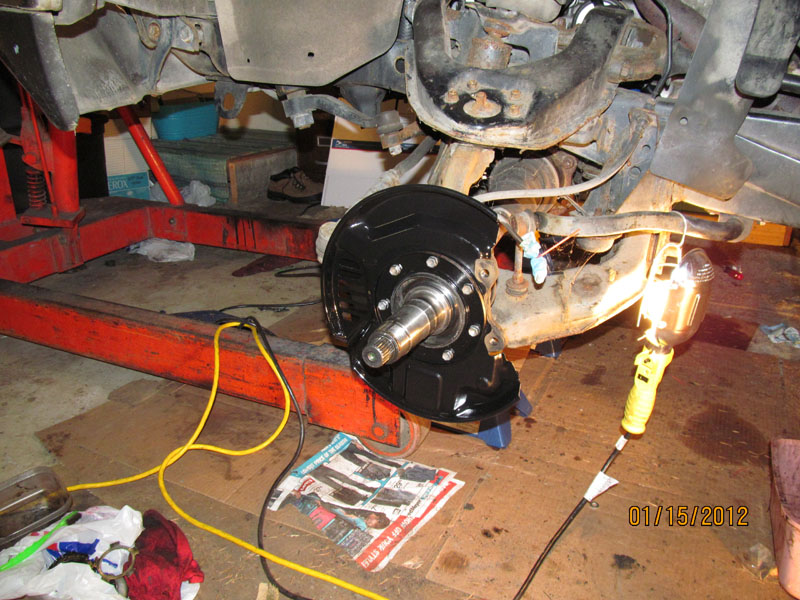
1/15/2012 � Cleaned up back plate re-installed
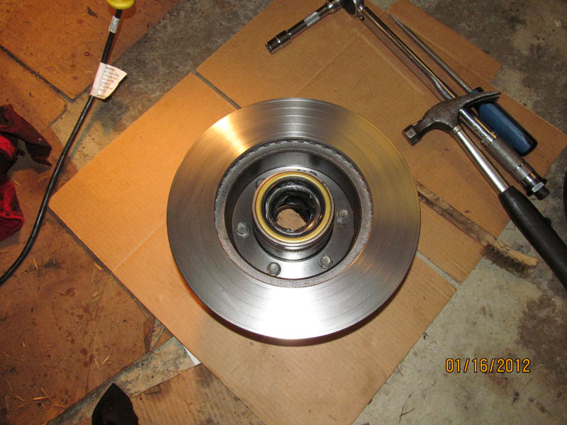
1/15/2012 � New rotor installed on reconditioned Hub
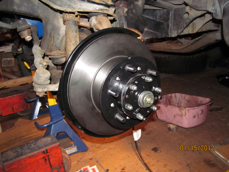
1/15/2012 � Reinstalled rotor assembly with new bearings in fresh packed grease.
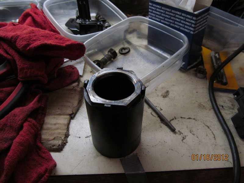
1/16/2012 � my custom tool to install the wheel nuts and torque them down.
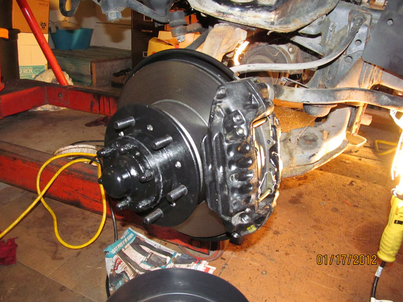
1/17/2012 � New calipers and pads installed on the rotors
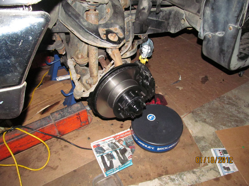
1/18/2012 � brakes bled and ready to go. Bleeding was simple following standard pump and hold
peddle down while opening bleed screw and escape trapped air into jar. Repeat a few times and good to
go. Now I need to get some tires.
The engine has blown and brakes rusted shut from sitting too long but the body and interior were still in
good shape.
I brought it home on a car carrier and parked in the back yard and there it sat. After a while I got the idea I might try to restore it to working order so I got a lift and pulled the engine. After tearing it down I discovered the problem was a bad rod bearing caused the Piston to actually hit the head at the top of the compression stroke. Simple enough, just rebuild the engine.
I next proceeded to tear it down, bag the parts and put them on the shelf. Using plastic storage bags and
makers, I tried to label everything as well as possible as I bagged them. It would have really helped if I
had taken a lot more pictures of the tear down as I could have used them later.
Over the next two years (yes really) I took various components down to the machine shop to have them worked on. First the block which was cleaned and checked for cracks, re-bored and deck resurfaced. The crankshaft was trash (from bad rod) so a new one there. The heads were reworked and valves redone, lifters shimmed, seals installed. New pistons, rings, bearings, gaskets, and such purchased. As each item
was reworked they were placed back on the shelf till I finally had them all done.
The in the fall of 2011, I was ready to try to put it all back together. I planned to use the vehicle as a test bed for a new digital gauge system (vGauge) my company makes so I was going to install additional
sensors on the engine during the rebuild. The plan was to add dual Exhaust Gas probes, block coolant temp, fuel pressure, and Transmission fluid temp. In addition, all the other standard gauges would be converted over to the digital format such as Engine temp, Oil PSI, Fuel Level, Volts, and so on. The
vGauge also is able to interface with the MAP/Air Flow sensor and O2 sensors so we see those readings as well.
This thread will cover the rebuild of the engine, adding the sensors, and installation and configuration of
the Digital gauge system.
11/3/2011 � Fresh block ready for paint � Tanked and bored and decked by machine shop
11/3/2011 - Over bored to fit new larger pistons
11/7/2011 � Painted and ready for new crankshaft. Main bearings in place
11/7/2011 � Crank in place
11/7/2011 � plastigauge check that clearances are correct.
11/7/2011 � Crank cap installed and torqued � do not forget the assembly lube
11/9/2011 � Pistons installed. Seems the rings can face up or down?
11/10/2011 � Rear main Oil seal prep work
11/10/2011 � cleaned up bolts for rear main seal
1/10/2011 � Oil Pan prep for paint
11/10/2011 � Painted Oil Pan
11/10/2011 � Rear Main Oil seal in place
11/10/2011 � New Oil pump to be installed
11/11/2011 � Cleaned up Oil Pan Bolts
11/11/2011 � Baffle and Oil Pickup installed. �The Right Stuff� for the pan seal
11/11/2011 � Oil Pan bolted down
11/13/2011 � Water and Oil pumps installed. Knock sensor installed with new cable.
11/13/2011 � 11/27/2011 Camera failure
11/27/2011 � Installed timing belt and tensioner
12/5/2011 -Timing Belt and Idler Pulley installed. Fan Bracket temporally placed till I find the rest of the
bolts
12/5/2011 -Air Intake Manifold placed and bolted
12/5/2011 - Cleaned fuel injectors. All new O rings but reused inserts since they looked fine
12/5/2011 - Fitted Fuel Injectors without fuel rails
12/5/2011 � Typical Fuel Rail setup
12/5/2011 - Spacers and nuts
12/5/2011 � Fuel Rails in place
12/6/2011 � Disassembled Valve covers to be cleaned. Had to grind off rivets on Oil disperser to remove
them for cleaning. With all this sludge, it would ruin a brand new engine in minutes.
12/6/2011 � Rear of block with view of rear main seal and heater pipe
12/7/2011 � Cleaned and painted Fuel Rail Crossover pipe and bolts
12/8/2011 � Cleaned up Valve covers before reassembly. Took 4 hours and 3 cans of brake cleaner and a
bottle of Super Clean. This stuff really works!
12/9/2011 � Drilled and tapped holes to remount the oil baffles. Used #6-28 thread an 3/8� machine SS
bolts
12/10/2011 � Re-installed Oil baffles in valve covers � look good as new and only took 4 days. But if they
were not clean, the whole job would have been wasted
12/10/2011 � Painted Valve Covers
12/10/2011 � Tapped Exhaust manifold to accept adjustable EGT probe (one on each head) Used a 3/5�
tap
12/10/2011 � fitted EGT probe. Can be adjusted latter. EGT probes measure up to 1600F and are very
responsive to engine load.
12/10/2011 � Cleaned and wire brushed exhaust manifolds before painting. Almost hate to paint them.
Used a 1500F header paint that I had used in the past and works well
12/17/2011 � Mounted Exhaust Manifolds and heat shields. New EGT probe in place, Made sure the
location would not interfere with anything else in the chassis.
12/17/2011 � Installed a 400F water temp sender before the Oil cooler. This will let us know the core
block water temp. Would have been good to install one on the outlet side of the cooler to be sure it was
doing anything (drop in temperature). Note Blue Oil Pressure sender on the left.
12/17/2011 � view of the passenger side Exhaust setup wit crossover tube installed. Much easier to do it
now then after the engine is in the truck
12/17/2011 - Finished putting on the Timing Cover after I was convinced the timing was correct. Put a
long screw driver in the number 1 cylinder hole and rotated crank till it topped out and mark on crank
pulley was at 0. Also checked that I had compression there at the same time by feeling for air escape.
12/17/2011 � Drained the Automatic transmission fluid and pulled the pan to change the filter. Prepped
and ready for paint
12/18/2011 � Drilled and tapped a 1/8� NPT hole to install a 400F temp sender in the Tran Fluid pan.
Made sure it was not going to get in the way inside. Also put backing nut on the inside since the pan
walls were kind of thin.
12/18/2011 � Backing nut on inside of tran fluid pan. Really a 1/8� NPT to 3/8� NPT reducer.
12/18/2011 � cleaned up tran pan bolts
12/18/2011 � Cleaned up magnets replaced in bottom of pan before rebolting to transmission. Applied
RTV to pan seal and on transmission. Most bolts go in OK with long extension but 3 of them are directly
under one of the support members and have to be started by hand and finished off with a wrench.
12/18/2011 � Torque converter in place after a quart of tran fluid being added. Was told it clicks in 3
times after being rotated but really only heard 2 clicks. Measured gap with straight and thought I was
right � but wait.
12/19/2011 � Engine up on lift waiting for truck
12/19/2011 - Truck being rolled in waiting for engine
12/19/2011 - Engine going in for first time. Lift had rollers so it was easy to move into place and slide
truck underneath and tilt engine to clear front axel.
12/21/2011 � Engine coming out of truck. But wait. It was just put in?? Well, after hours of trying, I
simply could not get the engine to bolt up to the transmission. I determined with much frustration, the
torque converter was not pushed in all the way and preventing the flex plate from seating properly. SO
out it comes
12/21/2011 � After playing around with the torque converter, I get it to snap in some more and now
have the clearance to drop the engine back in and bolt up to transmission. The problem is that the
clearance spec given in the manuals is after the torque converter is pulled back out to the flex plate, It
should be a good 2.5� FROM THE LIP OF THE Bell housing if properly seated all the way and then pulled
forward to the specified 1� after the engine is in.
12/21/2011 � Good view of the temperature probe on the Oil Cooler with Sense wire out to harness
12/21/2011 � Engine finally in � just in time for Christmas!. Found I had to undo the single bolt motor
mount from the chassis bracket in order to move the engine to get it to seat correctly. I had wanted to
avoid this as it very difficult to put the mount nut back in once the engine is in place. However, you can
reach in with a socket and barely get one click on the ratchet and slowly get that nut tightened down. I
do not see how anyone can do it with a torque wrench.
1/7/2012 � Installing Spark wires and distributor
1/7/2011 � Final bolt-down of Fan bracket and PS pump bracket. Note the order of the Power Steer
mount. First Pump then tensioner bracket. Be sure the Engine lift bracket is installed first as everything
else goes on top. I had to redo this 3 times.
1/7/2011 � Ready for Intake Air chamber. All Fuel rail crossover pipes and pressure relief valve are in
placed and tighten down. I was going to do a fuel pressure test but have a missing cold start injector and
fuel filter to install first
1/8/2012 � Air Chamber on for the first time � took about 3 times to get it right. Be sure to run the Cold
start injector fuel line and wire harness out first before bolting this thing down our you will be doing it
again. Also get the PVC hose on first. You will probably need a new one which I found out after putting
the Air Chamber on the second time.
1/8/2012 � Finally got all the Water hose and Vacuum line on. Not too hard as everything was cut to fit.
Had to replace the vac lines to the power steering as that were too brittle with age. I RTV all my water
hoses before I slip them back on and clamp. Never had a leak yet. Be sure to clean the insides out with
rag and screw driver soaked in Brake cleaner. Seem to work well to get a good seal.
1/9/2012 � Air valve installed.
1/9/2012 � Front view for vacuum lines
1/9/2012 � passenger side view of vacuum lines and hoses
1/9/2012 � New PVC hose from CARQUEST. Maybe not designed for this purpose but works just fine.
1/10/2012 � Throttle Cables and air ducts in place. All cleaned up with Super Clean � my third bottle.
1/10/2012 � My bypass of Pulsed Secondary Air Induction system that routes filtered air into the
exhaust for some sort of smog reduction � Don�t need it so I machined a block off plate
1/12/2012 � Cleaned and painted radiator � Really wish I had done a flow test first to make sure some
critter did not make a nest inside after 2 years sitting outside.
1/12/2012 � Cleaned up fan and hoses. Yea for Super Clean.
1/12/2012 � Painted belt pulleys
1/12/2012 � Installed Radiator, belts, and pulleys. RTV all the hoses
1/12/2012 � Ready to start � With Replaced Fuel Filter and drained fuel tank I was able to purge the fuel
line using the bypass diagnostic connector . Looked for leaks in fuel line and was convinced I was ready
to do a dry run. Put key in � turned it over and it cranked a few times. Let rest a second for fuel to
atomize and tried again � there it goes! Ran for second and I shut it down. Now add water to radiator.
Takes a while to trickle in but eventually get 2 gallons in and time to start again. A few more cranks and
off it goes. Have to keep peddle down slightly for a moment but eventually it holds idle by itself and we
have a running engine. Open up heater and let it run.
Now I need some brakes.
1/14/2012 � Both front brakes were really bad shape. Rotors and calipers were rusted so bad the wheels
would not spin at all. I found new Rotors for $34/ea at RockAuto.com (Christmas gift) and calipers at
Napa Auto for $45/ea so off with the old and on with the new.
1/14/2012 � While doing the rotors and calipers, I also got new wheel bearings since that had to come
out anyway
1/14/2102 � nice trick in pulling hub cover plate is undoing the six nuts and threading a 12 mm bolts
back in to pry off the cap � works really well
1/14/2012 � Found water in bearings � why am I not surprised!. Anyway the races looked fine with no
rust or pitting so I can just install new bearings.
1/14/2012 � Painted up brake parts �Again, spend more time cleaning the assembly.
1/15/2012 � Cleaned up back plate re-installed
1/15/2012 � New rotor installed on reconditioned Hub
1/15/2012 � Reinstalled rotor assembly with new bearings in fresh packed grease.
1/16/2012 � my custom tool to install the wheel nuts and torque them down.
1/17/2012 � New calipers and pads installed on the rotors
1/18/2012 � brakes bled and ready to go. Bleeding was simple following standard pump and hold
peddle down while opening bleed screw and escape trapped air into jar. Repeat a few times and good to
go. Now I need to get some tires.
Jan 26, 2012 | 03:45 PM
#2
Thread Starter
Registered User
Joined: Jan 2012
Posts: 5
Likes: 0
From: Southern Oregon
Oil leak
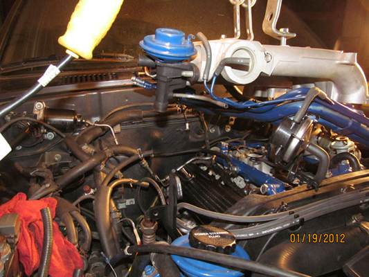
1/19/2012 � Oops, the dreaded leak. Got oil leak on the rear of the passenger side valve cover. Had to
trace it up from bottom of the bell housing. Thought it was a rear main seal but figured it could not have
been as it was new crank and seal. Anyway why is a new valve cover gasket leaking??
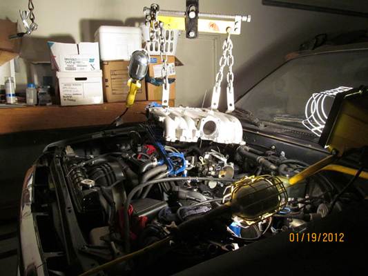
1/19/2012 � Off with the air chamber and vacuum hoses and throttle cables�
1/19/2012 � tried to keep the water hoses attached as they had been sealed with RTV but really did not
save much - all else had to be disconnected from the Air chamber to get at the valve cover.
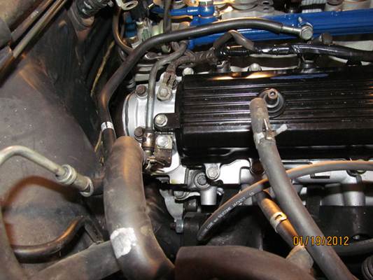
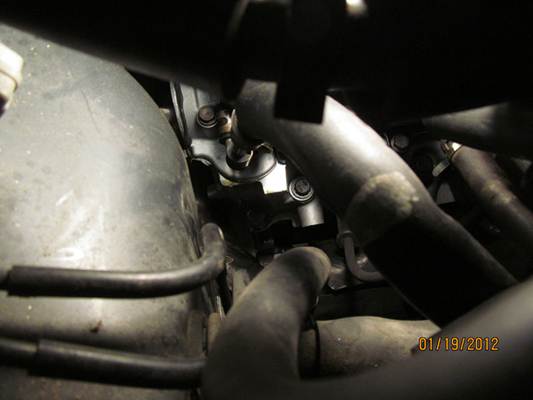
1/19/2012 � finally a good look at the source. Oil from right on the lower corner of the cover.
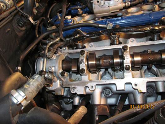
1/19/2012 � Looks as though the problem was paint. I do not know why, but some shops like to paint
the heads when they redo them � I always tell them not too � but it still happens. Then you have got to
remove all the paint from the sealing surfaces or else you wind up with leaks and having to take
everything apart again. So � its wipe everything down with solvent, clean all the surfaces, reapply with
the �Right Stuff� (really works!) and re-bolt everything back together again
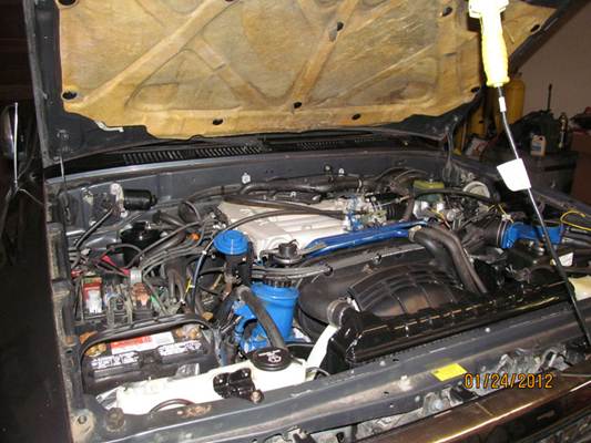
1/24/2012 � So I let everything set up and cure for a few days and put the old bald tires on and get
ready for a test drive. After warm up for 10-15 minutes � no oil leak.
1/24/2012 � Back out of garage and amazed it even moved after more than two years. Started to go
down the dive way and no issues. Climb up to the road and down and back for a mile and it actually
shifted. Came back and parked it � called it a day.
Jan 29, 2012 | 05:35 PM
#3
Thread Starter
Registered User
Joined: Jan 2012
Posts: 5
Likes: 0
From: Southern Oregon
Rear Brakes and axle
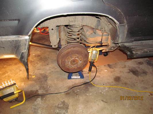
1/26/2012 � Started to work on rear brakes � as was typical, things were pretty rusted.
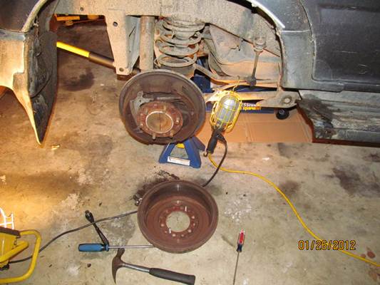
1/26/2012 � Took a lot of effort to get the drums off. Pads had worn unevenly and bound to drums
when I tried to pull them off. Drums are scrape but new ones are only $40/ea at NAPA.
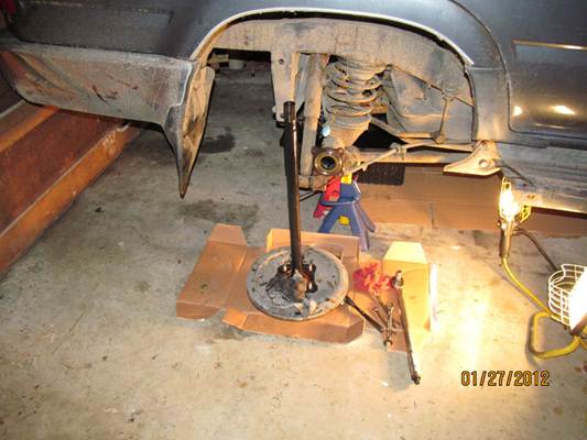
1/26/2012 � Pulled the rear axle. Very easy, just undo brake line and 4 bolts behind the back plate and
off they come. Chance to change out the oil seals since one looked like it was leaking.
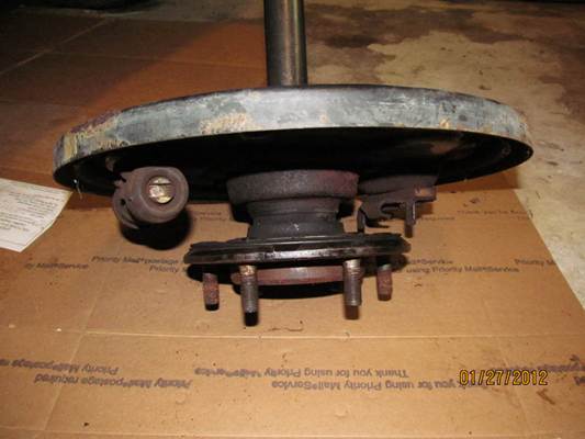
1/26/2012 � Well, it�s more than a leak. Fluid from the differential has wept through the bearing and its
history. Wobbles on the back plate like the earth�s rotation. I guess that�s why oil is all over the brake
shoes. SO, its new bearings and seals and a trip to the machine shop to have them pressed on. I might as
well do both sides as both bearings seemed to have some play. It will be few days at he shop so I will start to strip
and paint the rims.
Jan 30, 2012 | 06:11 PM
#7
Thread Starter
Registered User
Joined: Jan 2012
Posts: 5
Likes: 0
From: Southern Oregon
Digital Dash
1/28/2012 � It�s most of a day running around town to check out tires and have the old ones pulled off
the rims so I can start to scrape, brush, sand, paint the rims. Also got all the bearings and seals for the
real wheels and put them in the shop.
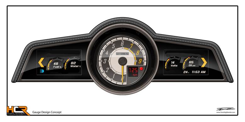
1/30/2012 � I was asked about the new digital instrument cluster. I was inspired by this design we are
working on for another vehicle.
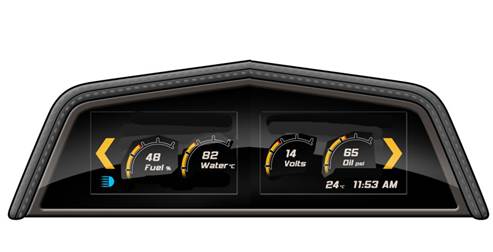
1/30/2012 � I have a vision of something like this for the 4Runner Dash with two 5.7� diag color VGA
screens. Will be able to have about 16 gauges and 12 indicators on dual screens that can be cycled
through by touch. RPM, MPH, ENG Temp, OIL PSI, Volts, Tran Temp, Tran PSI, L/R EGT, AMPS, Fuel Level,
Fuel PSI, Block Temp, Air Temp. Plus 12 indicators like Turn signals, High Beams, Door Open, Seat Belt,
and so on.
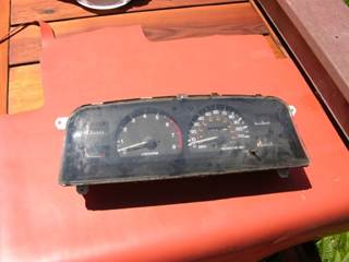
1/30/2012 � Removed original instrument cluster
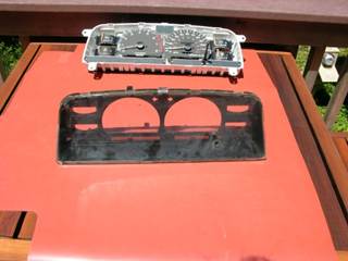
1/30/2012 � Broken down to get the bezel
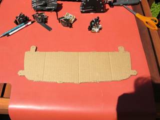
1/30/2012 � cardboard cutout of the sheet plate that would need to made to mount the displays.
1/30/2012 � mock up of how it fits in dash.
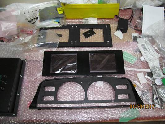
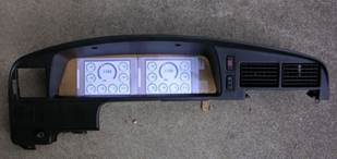
1/30/2012 � Dual color screens mounted behind test frame.
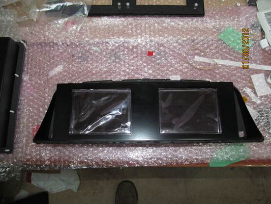
1/30/2012 � test frame placed over OEM bezel. I do not plan to use this frame for final but it does give
me an idea on how it looks and mount within the OEM bezel. I will final CNC machine the frame now that
I have all the dimensions correct. The displays are only 0.5� thick and have plenty of room behind the
panel. Black Box in the Engine compartment will collect and feed the data via Cat5 cable to dash.
Details to follow as I progress.
the rims so I can start to scrape, brush, sand, paint the rims. Also got all the bearings and seals for the
real wheels and put them in the shop.
1/30/2012 � I was asked about the new digital instrument cluster. I was inspired by this design we are
working on for another vehicle.
1/30/2012 � I have a vision of something like this for the 4Runner Dash with two 5.7� diag color VGA
screens. Will be able to have about 16 gauges and 12 indicators on dual screens that can be cycled
through by touch. RPM, MPH, ENG Temp, OIL PSI, Volts, Tran Temp, Tran PSI, L/R EGT, AMPS, Fuel Level,
Fuel PSI, Block Temp, Air Temp. Plus 12 indicators like Turn signals, High Beams, Door Open, Seat Belt,
and so on.
1/30/2012 � Removed original instrument cluster
1/30/2012 � Broken down to get the bezel
1/30/2012 � cardboard cutout of the sheet plate that would need to made to mount the displays.
1/30/2012 � mock up of how it fits in dash.
1/30/2012 � Dual color screens mounted behind test frame.
1/30/2012 � test frame placed over OEM bezel. I do not plan to use this frame for final but it does give
me an idea on how it looks and mount within the OEM bezel. I will final CNC machine the frame now that
I have all the dimensions correct. The displays are only 0.5� thick and have plenty of room behind the
panel. Black Box in the Engine compartment will collect and feed the data via Cat5 cable to dash.
Details to follow as I progress.
Trending Topics
Feb 1, 2012 | 06:28 PM
#9
Thread Starter
Registered User
Joined: Jan 2012
Posts: 5
Likes: 0
From: Southern Oregon
Rims
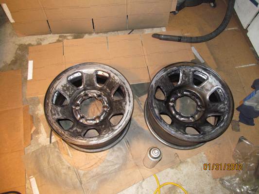
1/31/2012 � While waiting on the rear axles at the shop, I started on the rims. Have 2 tires off (the rear
of course) so had the tire place remove the rubber and started the process. Now, I have to say that this
has been the least fun so far on this project. The types of things living on the backside of these rims for
the past three years is beyond belief. The other big problem is getting any sort of power tools in there to
work out the rust � I really hate steel rims after this. Hours and hours of using every sort of tool I could
find and I think I got most of it. So, I then spray with rust remover and get ready to prime.
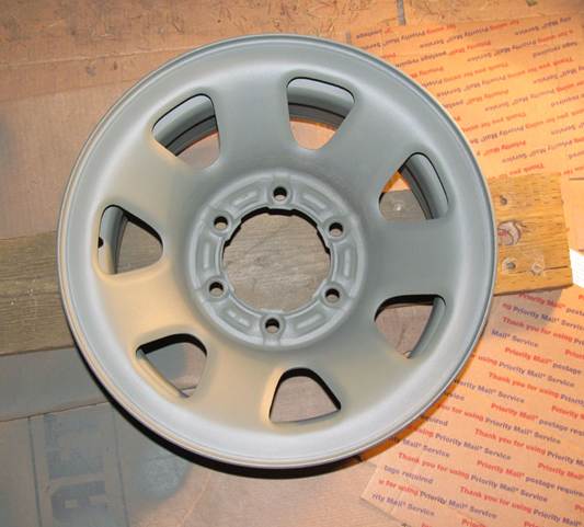
1/31/2012 � Primer coat (self etching) is always such a reward. Goes on easy with little runs and dry�s
fast. Makes things look so clean even though a few hours ago these things were ready for the dumpster.
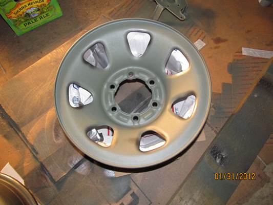
1/31/2012 � After the primer coat inside and out, I sprayed the back side a dark grey to match the truck
color. I did not want to go all black on the rims so I went for a 2-tone with dark grey behind and silver on
top. I used a cardboard box (USPS Med Flat Rate Box works great) and set it inside the rim. Used the
flaps to wedge in under the spokes so the top silver coat was masked from the grey underneath.
Worked out nice since it lifted the rim up off the floor.
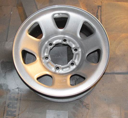
1/31/2012 � After spraying the top silver coat, I let it set for an hour and can remove the box from
below. No over spry on the gray underside. I then applied a 2-part clear coat over everything that really
made these look great � not bad for steel rims after all. Since all these coats of paint have to be done on
top of each other (8 total) before they fully setup (or else it will wrinkle) it took about 6 hours. Finished
at 1:30 AM. Now I have to do it all over again for the other 2 tires. Think I will find a sandblaster.
Feb 1, 2012 | 07:42 PM
#10
Registered User
Joined: Oct 2008
Posts: 1,018
Likes: 2
From: New Britain, CT
Awesome job on the engine! Only thing I would have done is add aftermarket headers and rework the cross-over pipe. Word on the street is that's what makes the 3.0 V6 eat head gaskets so much, it'd be a shame to have a HG blow after such a nice rebuild. Oh well, looks like it's water over the dam now. Still great work!

Thread
Thread Starter
Forum
Replies
Last Post
RedRunner_87
95.5-2004 Tacomas & 96-2002 4Runners (Build-Up Section)
84
Jun 1, 2021 01:51 PM
MMA_Alex
86-95 Trucks & 4Runners (Build-Up Section)
25
Apr 18, 2017 05:07 AM


