

OEM e-locker switch w/ DIY Relay Circuit?
 Sep 18, 2008 | 05:42 PM
#1

Thread Starter
Registered User
Joined: Jul 2007
Posts: 49
Likes: 0
From: Georgia
I am getting ready to put an e-locker in my '85, and my question is:
Has anybody made their own relay circuit, but for use with the stock switch (Off-On)?
I want to try to make it look as OEM as possible (in the cab) and use the Toyota switch, but try to avoid paying the $100 for the diff lock ECU.
All of the write-ups I have read, they use a DIY relays with a 3 way switch (On-Off-On), or the stock diff ECU with the stock switch (Off-On).
Sep 22, 2008 | 05:16 PM
#3

Registered User
Joined: May 2006
Posts: 106
Likes: 0
From: Cedar City, UT
I am getting ready to put an e-locker in my '85, and my question is:
Has anybody made their own relay circuit, but for use with the stock switch (Off-On)?
I want to try to make it look as OEM as possible (in the cab) and use the Toyota switch, but try to avoid paying the $100 for the diff lock ECU.
All of the write-ups I have read, they use a DIY relays with a 3 way switch (On-Off-On), or the stock diff ECU with the stock switch (Off-On).
Has anybody made their own relay circuit, but for use with the stock switch (Off-On)?
I want to try to make it look as OEM as possible (in the cab) and use the Toyota switch, but try to avoid paying the $100 for the diff lock ECU.
All of the write-ups I have read, they use a DIY relays with a 3 way switch (On-Off-On), or the stock diff ECU with the stock switch (Off-On).
Last edited by Oatmeal; Sep 23, 2008 at 06:36 PM.
Sep 24, 2008 | 01:48 PM
#4
Thread Starter
Registered User
Joined: Jul 2007
Posts: 49
Likes: 0
From: Georgia
So basically, I will just use this locker control circuit, but omit the SPDT "Control Switch" and replace it with a third SPDT relay (activated by the OEM locker switch).
Last edited by BigO; Sep 24, 2008 at 01:55 PM. Reason: web link added
Sep 24, 2008 | 05:43 PM
#5
Registered User
Joined: May 2006
Posts: 106
Likes: 0
From: Cedar City, UT
Thats it! Thanks!
So basically, I will just use this locker control circuit, but omit the SPDT "Control Switch" and replace it with a third SPDT relay (activated by the OEM locker switch).
So basically, I will just use this locker control circuit, but omit the SPDT "Control Switch" and replace it with a third SPDT relay (activated by the OEM locker switch).
 My buddy uses Toyota power window switches (momentary) on his lockers but, I didn't like how you have to keep pushing it till it locks. If you're installing a rear locker, I would consider installing another switch to interupt power to the whole shebang so, you don't accidentally engage the locker going 75mph down the highway!
 Let us know how that works out!----------Hans
Last edited by Oatmeal; Sep 24, 2008 at 05:54 PM.
Sep 24, 2008 | 06:58 PM
#6
Registered User

Joined: Jan 2006
Posts: 684
Likes: 2
From: North Georgia
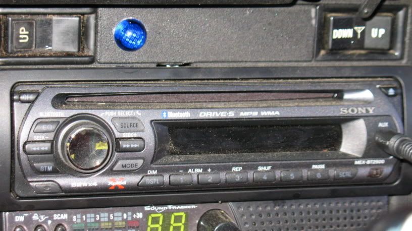
I just finished mine recently, using a dual SPDT relay scheme that is well documented around here. An illuminated master power switch, located near the E-Brake, locks the system out until I want to use it. A spare rear-window switch gave me the momentary on-off-on rocker that I wanted to use. It fits nicely in the panel knock-out above my stereo, and I put a blue ON indicator next to it. You hold the switch in the position you want for about one second, and the motor goes there. Sometimes you have to move the vehicle slightly before it engages, and then the light comes on. This is the best mod I've done to the truck!
Sep 25, 2008 | 12:56 PM
#7
Thread Starter
Registered User
Joined: Jul 2007
Posts: 49
Likes: 0
From: Georgia
Yep, I plan to add a relay activated by the "4WD" dash light, so that power is available only when I am in 4-High or 4-Low.
Trending Topics
 Jun 20, 2011 | 07:31 AM
#9
Thread Starter
Registered User
Joined: Jul 2007
Posts: 49
Likes: 0
From: Georgia
I know it has been a while, but I wanted to post what I did 3 years ago, to add to the many options for the e-Locker retrofit. My main goals for this project were:
1) For it to be simple to operate and reliable.
2) Easy to trouble shoot.
3) In the cab, for it to look very clean, as if Toyota originally offered this on these trucks.
4) To prevent it from accidentally engaging while driving around in 2WD.
I used a three relay system to control the locker off/on, and a fourth relay to switch on a red LED to indicate that the motor is in transition (on). And the green LED indicates that the locker is fully engaged.
I used the Hella relay block, with Hella relays. This emulates the OE Diff Lock Controller, and allowed me to use a Toyota “RR Diff Lock” switch.
The two LED’s are next to the switch. I hit them with a couple of coats of that “Translucent Black” spray paint that kids use to black out their taillights, so that these were not too noticeable unless lit.
Last edited by BigO; Jul 31, 2011 at 10:37 PM.
Jun 20, 2011 | 07:35 AM
#10
Thread Starter
Registered User
Joined: Jul 2007
Posts: 49
Likes: 0
From: Georgia
I created a �4WD� hot bus that only activates with the truck in 4lo or 4hi. I did this by adding a 60A fusible link where that was intended for the Diesel stuff. From this link, I ran power through a 75A power relay, which is activated by the T-Case switch for the �4WD� dash indicator light.
Mar 7, 2012 | 12:06 PM
#11
Registered User
Joined: Mar 2012
Posts: 1
Likes: 0
From: Idaho
I just wanted to thank you for this wiring diagram... i know this is a pretty old topic, but i couldn't find it anywhere else... I too wanted to use the stock factory switch, and i couldn't find a write up anywhere else. I tried to follow your directions but in my own stupidity i mixed up my Lock Limit Switch wires and burned up my motor because the motor stayed on even after it moved into locking position. It was a dumb mistake on my part...
I also took the liberty of slightly modifying your diagram to give people a better idea of how the wiring inside the motor worked and what the wire colors are...

i just wanted to thank you for actually taking the time to come back and tell us how you did it!
I also took the liberty of slightly modifying your diagram to give people a better idea of how the wiring inside the motor worked and what the wire colors are...
i just wanted to thank you for actually taking the time to come back and tell us how you did it!
Last edited by Mega_Mormon; Mar 7, 2012 at 12:09 PM.

Thread
Thread Starter
Forum
Replies
Last Post
justdifferentials
Vendors Build-Ups (Build-Up Section)
14
Jun 11, 2017 08:36 PM
charlie_fong
General Vehicle Related Topics (Non Year Related)
0
Sep 27, 2015 10:06 PM
runnermedic
95.5-2004 Tacomas & 96-2002 4Runners
13
Sep 21, 2015 05:20 PM


