
Custom Built 3VZE Upper Intake
 Apr 22, 2014 | 07:37 AM
#1
Thread Starter
Registered User
iTrader: (1)
Joined: Nov 2012
Posts: 358
Likes: 0
From: Elko NV, at the foot of the Rubys
Custom Built 3VZE Upper Intake
Good Day All!
I wanted to post this here to get more thoughts on how this will work, and any opinions on design changes. I have always thought the upper intake was extremely restrictive, and on my quest for more horsepower, I came up with this:
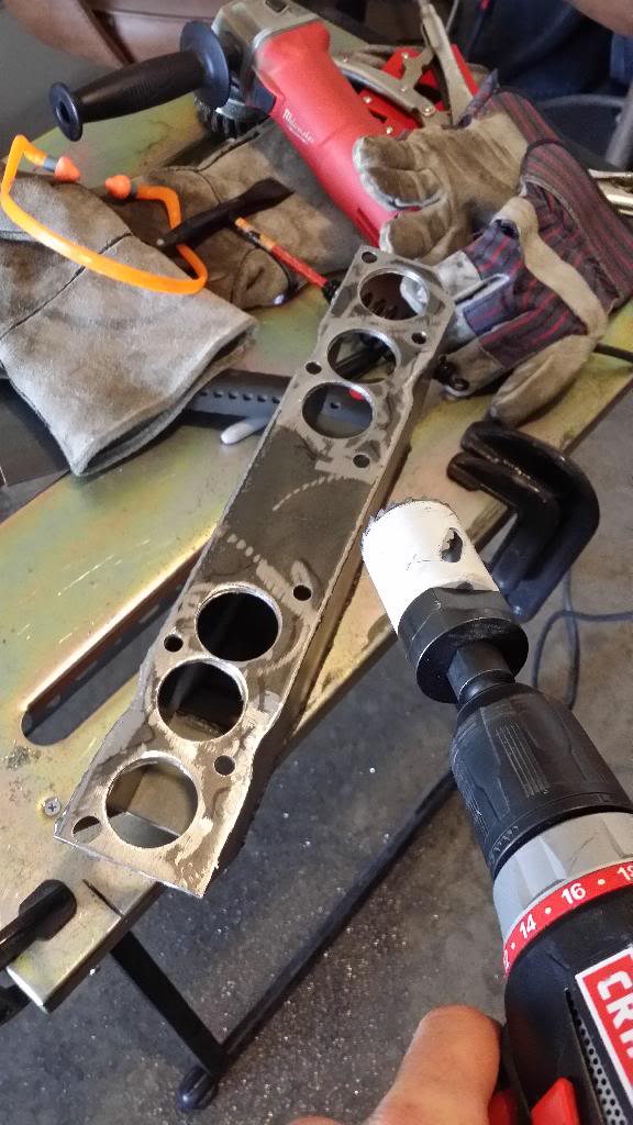
Custom Upper intake anyone?

This took WAY too long, but they just barely line up with the lower intake.
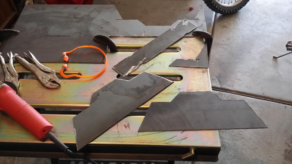
Welding on thicker steel is MUCH better.

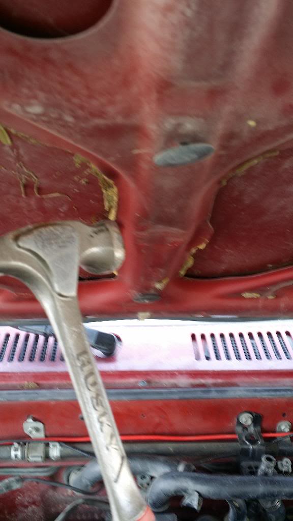
I had a little hood clearance issue...
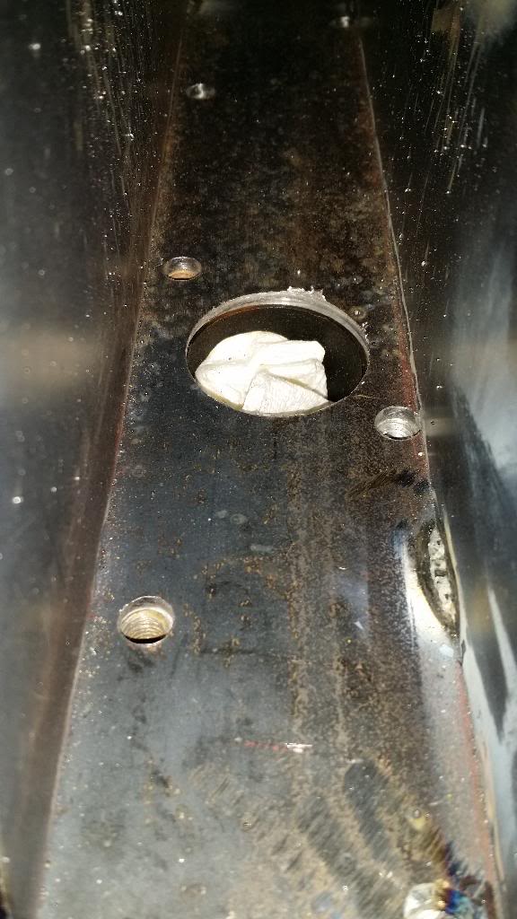
An inside view
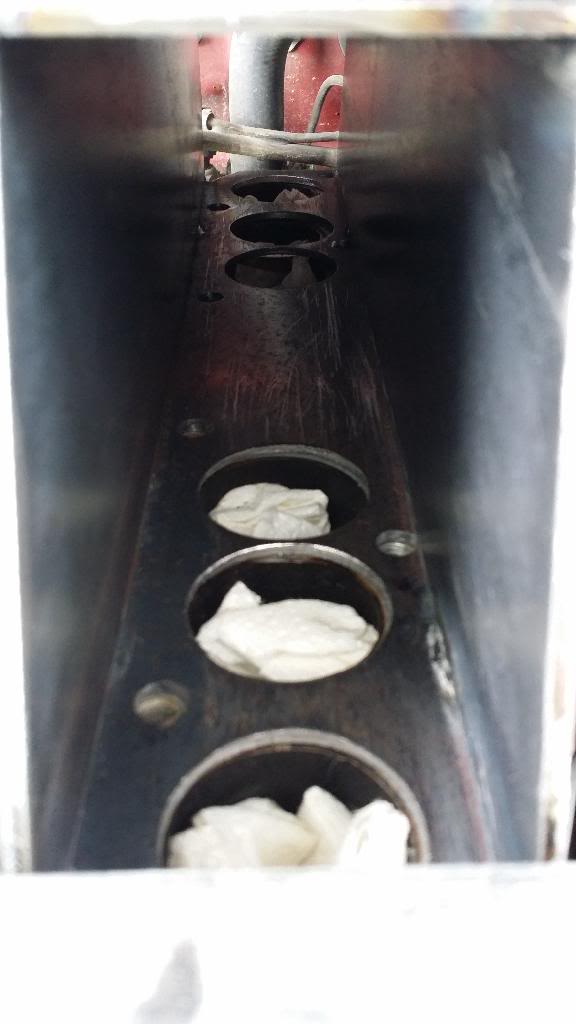
The problem with cutting a round hole with a flat grinding disk... you get a not so circle opening, but it will work. The throttle body opening is smaller than this.

I tapped into the side and mounted the throttle body. So far a nice fit.
All I have left is the cold start injector to install, throttle cable, and vacuum ports for brakes and fuel regulator.
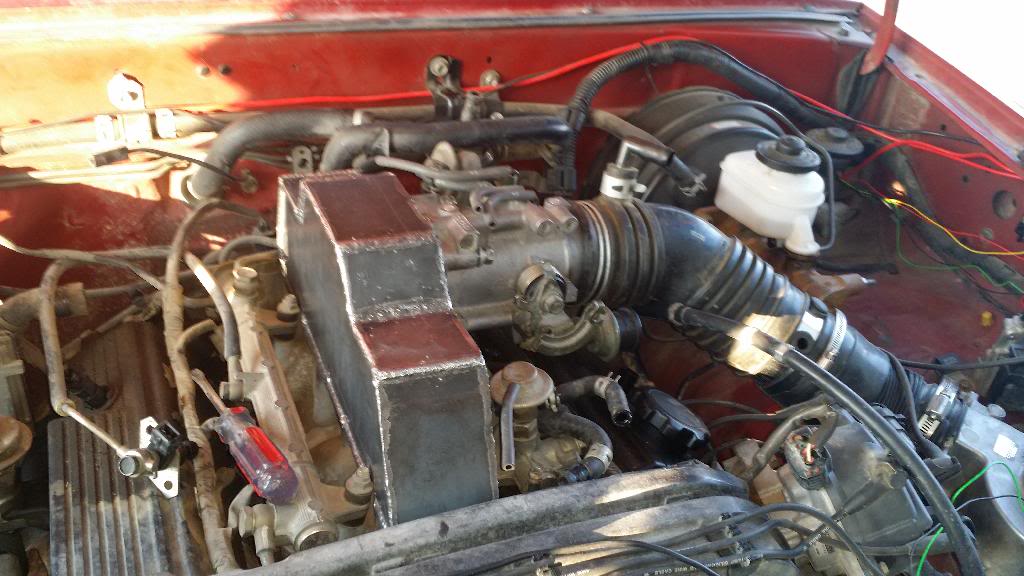
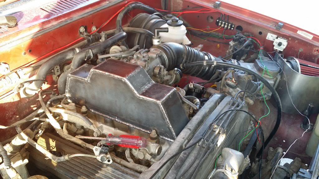
I didnt realize it at first, but it looks like another little truck under the hood...
My thoughts on the airflow, which I wish I would have made the top of the intake one piece instead of making it change direction twice, is that I am actually creating more turbulence with this setup. Why? Well the air collides into the other wall, which it did in the other intake. But then it has to pass by the length of the bolts that will go through the top of the intake to hold it down. So after it collides with the wall, passes by the length of the bolts on the side, then it enters the lower intake, where the lip itself will create some turbulence.
So, turbulent air is slower air. We want laminar flow. Well I do not have the capablity of bending tube, so my hopes are that the larger chamber will allow the engine to draw a larger volume of air in, therefore offsetting the turbulent air. As long as the volume of air supercedes the turbulent air, this will be a success. If not, well then I learned a lot today.
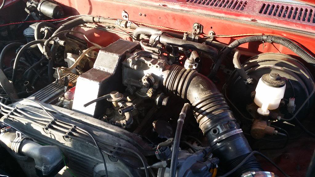
Here it is as it sits now:
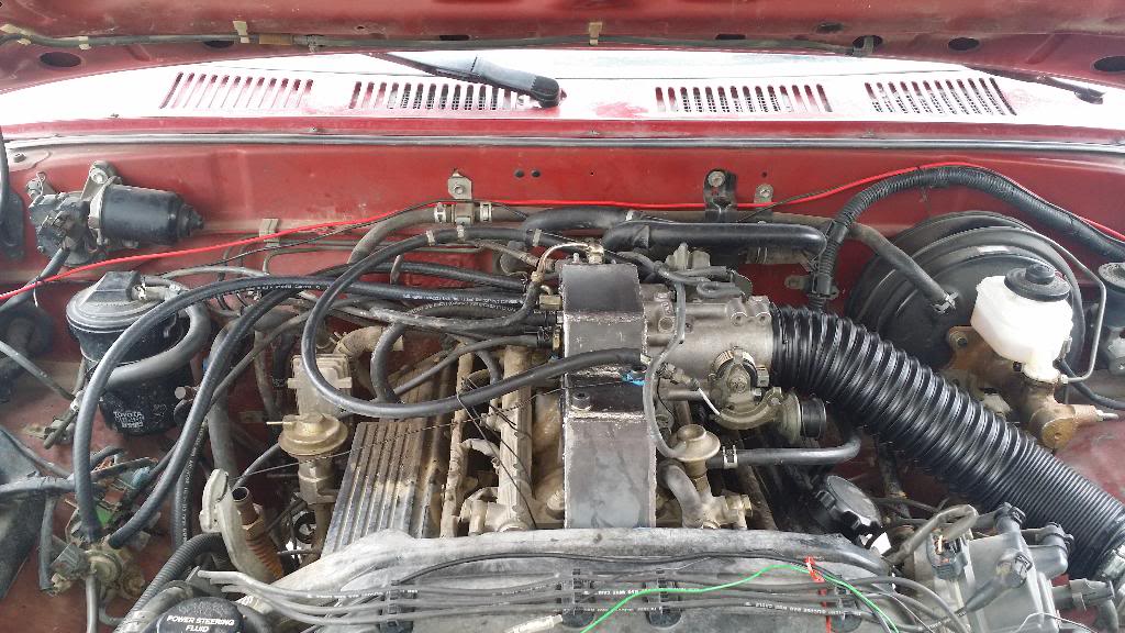
so far I believe everything is hooked up in the right order. Truck Runs, but not great, got quite a few vacuum leaks to seal up.
How important is it to have vacuum at the valve cover port next to the oil cap? I have seen people put breathers there, do I need vacuum? truck runs like crap without it, but do I just need to raise the idle or what?
Comments? Suggestions? What are your guys technical thoughts on how this will work?
Thanks!
I wanted to post this here to get more thoughts on how this will work, and any opinions on design changes. I have always thought the upper intake was extremely restrictive, and on my quest for more horsepower, I came up with this:
Custom Upper intake anyone?


This took WAY too long, but they just barely line up with the lower intake.

Welding on thicker steel is MUCH better.

I had a little hood clearance issue...

An inside view

The problem with cutting a round hole with a flat grinding disk... you get a not so circle opening, but it will work. The throttle body opening is smaller than this.

I tapped into the side and mounted the throttle body. So far a nice fit.

All I have left is the cold start injector to install, throttle cable, and vacuum ports for brakes and fuel regulator.

I didnt realize it at first, but it looks like another little truck under the hood...

My thoughts on the airflow, which I wish I would have made the top of the intake one piece instead of making it change direction twice, is that I am actually creating more turbulence with this setup. Why? Well the air collides into the other wall, which it did in the other intake. But then it has to pass by the length of the bolts that will go through the top of the intake to hold it down. So after it collides with the wall, passes by the length of the bolts on the side, then it enters the lower intake, where the lip itself will create some turbulence.
So, turbulent air is slower air. We want laminar flow. Well I do not have the capablity of bending tube, so my hopes are that the larger chamber will allow the engine to draw a larger volume of air in, therefore offsetting the turbulent air. As long as the volume of air supercedes the turbulent air, this will be a success. If not, well then I learned a lot today.
Here it is as it sits now:


so far I believe everything is hooked up in the right order. Truck Runs, but not great, got quite a few vacuum leaks to seal up.
How important is it to have vacuum at the valve cover port next to the oil cap? I have seen people put breathers there, do I need vacuum? truck runs like crap without it, but do I just need to raise the idle or what?
Comments? Suggestions? What are your guys technical thoughts on how this will work?
Thanks!
Apr 22, 2014 | 07:39 AM
#2
Thread Starter
Registered User
iTrader: (1)
Joined: Nov 2012
Posts: 358
Likes: 0
From: Elko NV, at the foot of the Rubys
Also, what do you think about cork gaskets? I need to make a custom gasket that is thick and compressible, do you trust cork to seal out air? Where can I get some thick cork gasket sheets to cut out a template? I am currently using silicone, but it isn't working very well, and I can't clean up the surfaces and pour new sealant everytime I take this thing off.
Apr 22, 2014 | 08:26 AM
#4
Thread Starter
Registered User
iTrader: (1)
Joined: Nov 2012
Posts: 358
Likes: 0
From: Elko NV, at the foot of the Rubys
Thanks blake! Well the truck runs, but a few vacuum leaks are keeping me from running it right now. I won't know the true performance gain until I take it up the summit this weekend, but just driving around the block it is doing well, again I believe the leaks are hurting the overall performance, I can hear the air sucking in everytime I romp on it.
Apr 22, 2014 | 10:43 AM
#6
Thread Starter
Registered User
iTrader: (1)
Joined: Nov 2012
Posts: 358
Likes: 0
From: Elko NV, at the foot of the Rubys
Thanks vital! and you are exactly right, the length and size of the runners has a lot of physics behind it that change the characteristics of the engine. Unfortunately I don't have the ability to build runners, so this is my alternative. My theory is that I will gain more top end than anything else. We will see hopefully this coming weekend, if not sooner.

Apr 22, 2014 | 12:31 PM
#7
Registered User
Joined: May 2008
Posts: 1,063
Likes: 2
From: Knoxville, TN
Sooo, how is this mounted to the engine? Not to rain on your parade, but if you put bolts inside to secure it, then welded plates over that, you will have a fun time when you do a head gasket.
Trending Topics
Apr 22, 2014 | 12:41 PM
#8
Thread Starter
Registered User
iTrader: (1)
Joined: Nov 2012
Posts: 358
Likes: 0
From: Elko NV, at the foot of the Rubys
No worries wii! lol, I am glad you have my back. It is as easy as taking off the original upper intake. In one of the last pictures, you can see 4 allen bolts that bolt in from the top (source of a vacuum leak or two). I can take it on and off with ease. I welded the entire unit together before I bolted it to the truck, obviously with a lot of trial and error fits. In fact, I can take the lower and upper intake off together as a unit now if I wanted to now that I have easier access to everything.
I thought about bolting it from the inside, through the throttle body access, but it deemed itself a bit too small to do.
I thought about bolting it from the inside, through the throttle body access, but it deemed itself a bit too small to do.
Apr 22, 2014 | 06:14 PM
#9

Registered User
Joined: Oct 2013
Posts: 133
Likes: 1
I would keep an eye on air fuel ratio on each cylinder!
Or at very least each bank. We normally keep an eye out with EGT's on each cylinder. Problem being is that you have caused unnatural turbulence in the upper intake and you will not get equal air to each cylinder. You may be able to counteract this by dishing the wall opposite to the throttle body. Please be careful with mods like this as a lean cylinder or two is an engine killer.
Apr 23, 2014 | 06:09 AM
#10
Thread Starter
Registered User
iTrader: (1)
Joined: Nov 2012
Posts: 358
Likes: 0
From: Elko NV, at the foot of the Rubys
Thanks 87-SR5, for the heads up! You are dead on right with the turbulence, which has been a fear of mine the whole time. Turbulence can act in strange ways, but I am hoping that just the shear volume of the chamber will allow each cylinder to draw the same amount of air, but like you said, the turbulence that is generated could prohibit that.
I am glad you brought it up, cause I am going to richen the VAFM for initial testing to help ensure I don't get any lean cylinders. I would rather run too rich in this case. If I could monitor each bank I would.
Thanks for the input! That is what I am looking for.
I am glad you brought it up, cause I am going to richen the VAFM for initial testing to help ensure I don't get any lean cylinders. I would rather run too rich in this case. If I could monitor each bank I would.
Thanks for the input! That is what I am looking for.
Apr 23, 2014 | 04:29 PM
#11
Registered User
Joined: Oct 2013
Posts: 133
Likes: 1
At least use a wideband.
That way at least if you see it run lean you know about it. $150 well spent. An egt analog gauge is $120 and each additional probe is $20. Would be time consuming but plug and unplug them just to check them. I use my multimeter.
May 1, 2014 | 07:40 PM
#12
Thread Starter
Registered User
iTrader: (1)
Joined: Nov 2012
Posts: 358
Likes: 0
From: Elko NV, at the foot of the Rubys
HE'S ALIVE!!! alright, so Jake is running again, and he is purring like a kitten, no more vacuum leaks, the cork gasket maker worked great. This is the smoothest this engine has run for me since I bought it, I kid you not. It idles smooth, no hesitations, no pulsing, just butter smooth... awww yeah...
Power? I feel I gained substantial low end torque. Now when I step on it, I feel the frame twist and the truck push on my back, and I can get up to speed in second gear alone. Now I need to do more controlled runs to get numbers for you all, which will hopefully take place this weekend.
My plan is to have the wife help me. We will do a few runs from 10-60 mph runs with the custom intake to get an average acceleration time. I will clean up my old intake and reinstall it, and do the same runs to get an average. This will tell me how much it helped.
I need to reinstall the old intake anyway. When putting the custom intake back on, one of the throttle body bolt holes stripped out, so I had to use a c clamp to hold it on for testing lol. I will have to fix the hole to run it permanently. as far as I can hear, there is no apparent knocking, so far so good.
May 1, 2014 | 08:08 PM
#14
Registered User
Joined: May 2010
Posts: 2,587
Likes: 7
From: Ofallon Missouri
Couple questions.
Why did you do this? I imagine it is just because you could kinda thing.
Im sure you realize that it really can't be any better than stock. Im sure in fact its worse. My real fear....is you are gonna run a couple cylinders lean without ever knowing it...and burn a valve or piston up. Runners are in intakes for a reason. Freaking engineers with flow benches literally study the flow patterns a swirls and base designs off this.
With the mailbox you got on there...no way the cylinders are feeding evenly. Physically impossible. Think about that and how certain cylinders are going to hog the fuel..and lean others out.
May 1, 2014 | 09:37 PM
#15
Thread Starter
Registered User
iTrader: (1)
Joined: Nov 2012
Posts: 358
Likes: 0
From: Elko NV, at the foot of the Rubys
Hmmmm, thought a guy would get a little appreciation for thinking outside the box. Sorry to upset you, but here are my reasons:
Ever seen the intake on a 12 valve cummins? It uses a mailbox as well, this is where my idea stemmed from. Now given most cummins are boosted, there are a fair share that are not.
I hope you meant which cylinders hog air and not "hog fuel". Each injector fires the same amount of fuel assuming they are within spec of each other at a constant rpm. This intake, sure, some cylinders may starve more than others, but I would rather run rich than lean any day. Yours and mine concerns should be are the injectors feeding enough fuel given the larger volume of air being introduced, which is why I increased the fuel delivery via the afm to help protect against lean conditions.
This is a large chamber. Look at the stock upper intake, you will see that every runner is smaller than the lower intakes runners considerably, and the main throat that the throttle body bolts to is smaller yet compared to the throttle body. This is a restriction. Try breathing through a straw and tell me it is not more work. My theory was by allowing each cylinder to draw the air it needs from a vast chamber, I just made its pumping job that much easier, and that air the cylinder drew in can easily be displaced in the chamber by more incoming air with less restriction.
Do i have numbers to prove any of this? No, because I am a weekend warrior and can't afford a flow bench. Can I get numbers? You bet I can, with enough oxygen sensors, custom built exhaust headers, fuel pressure gauges and a dyno, I can see if this makes a difference, but it is going to take me time. This was an initial test to see if I was on the right track. There are plenty of designs I have thought through, but this one made the most logic sense at the time due to the location of the throttle body which is symmetrically located to each bank of cylinders, thus allowing the most even distribution versus other designs.
All I am asking is for ideas to help make this work. Help me out, give me ideas to improve rather than shatter my hope for a more efficient 3vze. Who else has tackled this? I couldn't find anything on it, but I like the challenge. As I said before, I will have to put my original intake back on until I can fix the threads on this custom one, but I get the sense the first and most important thing I need is to have AFR numbers from each cylinder to allow everyone to see it in action so we can improve from there. I already have ideas on how to monitor each cylinder, and with other users input I would hope we could do this on a budget. Forgive me if I sound on edge, trying to tread lightly here.
May 1, 2014 | 10:00 PM
#16
Registered User
Joined: May 2010
Posts: 2,587
Likes: 7
From: Ofallon Missouri
We are just having a discussion. No one will get butthurt.
I get what you are saying cause this is just an upper intake.
Just an air chamber. No actual air/fuel mix.
Im just saying...dozens of engineers designed an upper for this thing. It works. What do you hope to gain? Power?
I would imagine one would open the terrible crossover exhaust up with a set of headers first. Or maybe even a k and n to open up the intake track.
You are building a pro street box manifold for a stock 3.0 with no other mods.
Its a case of cart before horse. You are improvong something that is not the bottleneck to power...so there should be no gains there.
And then there is the turbulence issue. You have erased all factory airflow patterns and now have no idea what it happening in there. Is the velocity down #1 runner faster now? Not only are there lean/rich issues...there are swirl and quench issues as well...as you have altered the designed airflow pattern.
My theory is....you may have something there....after headers...intake track...injectors and a poweradder...then that volume...underboost...may be advantageous. Maybe.
But with te choked exhaust...and intake tubing...a bigger upper manifold does zip.
May 1, 2014 | 10:20 PM
#18
Thread Starter
Registered User
iTrader: (1)
Joined: Nov 2012
Posts: 358
Likes: 0
From: Elko NV, at the foot of the Rubys
Thanks for the discussion Highlux. The ISR mod and crossover elimination mod have been done, so this is not completely stock. Custom headers for cylinder monitoring are in design right now. Turbulence and quench characteristics have been altered dramatically, which I agree with. How much? Well I hope to find out soon enough.
Ideally, I would have built cylindrical runners that were larger to match the porting of the lower intake that were much shorter and met at a larger chamber the throttle body bolted to. This would have ensured more even flow, but with limited tooling this was the next best option. Trying to port the original intake would be impossible without cutting it in half and having a shop do the work to weld it back up, which I have seen done before, but the length of the runners is unnecessary.
Thoughts on the length of the runners?
May 1, 2014 | 10:37 PM
#19
Thread Starter
Registered User
iTrader: (1)
Joined: Nov 2012
Posts: 358
Likes: 0
From: Elko NV, at the foot of the Rubys
 , but hey, we are all here to learn and share and I am willing and wanting others help, so thanks, yours and others input has me thinking about this, and let's see if this is just a total bust or a score for the 3vze. (worst case I blow the engine and I have another reason to tell the wife I need an engine swap, which won't go over well because she knows what I am up to lol
  )
May 2, 2014 | 04:41 AM
)
May 2, 2014 | 04:41 AM
#20
I had a 2.9 Ford with a similar Plenum down the center. Not sure why Toyota uses a flat style that lays over the entire motor. To be fair to the engineers, they are under pressure to meet emissions and different other things. Another as I understand is they some times have to make the motor fit into the body.
Only way to find an improvement is to think out side the box. I already like how it clears the top of the motor. Tons of vendors have done well improving manufactures products.
Only way to find an improvement is to think out side the box. I already like how it clears the top of the motor. Tons of vendors have done well improving manufactures products.


