
Water and engine coolant temp difference?
 Oct 27, 2007 | 11:49 PM
#1
Thread Starter
Contributing Member
Joined: Jun 2005
Posts: 3,415
Likes: 10
From: Phx, AZ
Water and engine coolant temp difference?
Getting to work on my 3.4 swap. Not used to posting in this section with my '91 4Runner. Guess I am stepping up. 
Short question: Does anyone know if the engine coolant sensor and water temperature sensor on a '96 3.4 send the same signal and monitor the same thing... engine temp? And how the fact that they are wired differently might effect things?
Long question: I am starting to figure out the wiring and this is my dilemma (you'll probably have to read this at least twice, cause it is as confusing as H)
This is what the engine actually has:
Engine coolant sensor is located at the top rear of the block. The sensor is self grounding, and only has one wire leading to it, which is yellow/red (Y-R).
Water temperature sensor is located at the top front of the block and has two wires leading to it. One is brown/ blk (BR-B) and the other is green/ red (G-R).
This is what the '96 wiring diagram shows: (which has been spot on for everything else so far):
Engine coolant sensor going to the ECU with two wires, not one. Two wires shown on the digram are G-Y (to G-R after plug) and BR-B. So, wiring diagram is showing me the two wires for the water temp sensor going to the engine coolant sensor... which is impossible. Coolant sensor has only one wire going in.
Backwards detail:
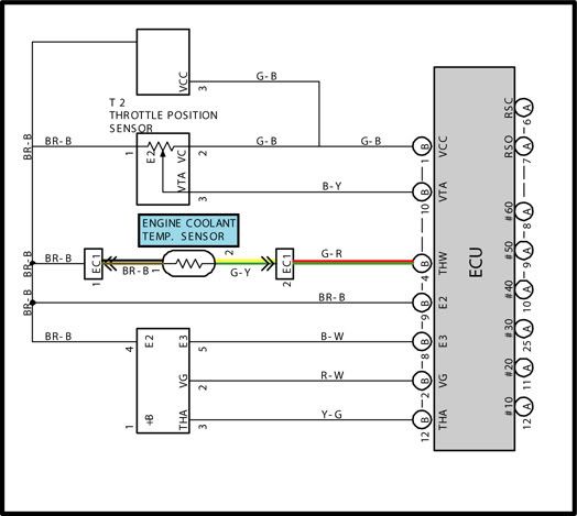
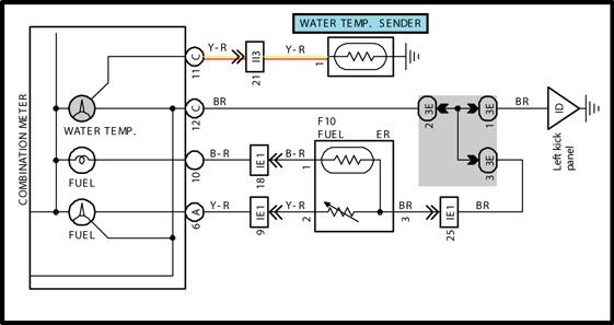
Now the wiring diagram shows the Water temperature sensor going to the gauge cluster with a single Y-R wire, where in fact the water temp sensor needs two wires.
Detail:
Now, if you have been able to follow this lengthy explanation you'll see that I have some conflicting information. Existing wiring patterns and colors don't match what the wiring diagram shows. I want to hook up the sensors correctly, and I am leaning towards ignoring the wiring color... but don't want to send incorrect signals to the ECU or gauge or worse blow something up.
Basically... I am confused on how the sensors differ (one with two wires, one with a single wire) and how this may effect the gauge or ECU.
WWYTD??
Short question: Does anyone know if the engine coolant sensor and water temperature sensor on a '96 3.4 send the same signal and monitor the same thing... engine temp? And how the fact that they are wired differently might effect things?
Long question: I am starting to figure out the wiring and this is my dilemma (you'll probably have to read this at least twice, cause it is as confusing as H
)This is what the engine actually has:
Engine coolant sensor is located at the top rear of the block. The sensor is self grounding, and only has one wire leading to it, which is yellow/red (Y-R).
Water temperature sensor is located at the top front of the block and has two wires leading to it. One is brown/ blk (BR-B) and the other is green/ red (G-R).
This is what the '96 wiring diagram shows: (which has been spot on for everything else so far):
Engine coolant sensor going to the ECU with two wires, not one. Two wires shown on the digram are G-Y (to G-R after plug) and BR-B. So, wiring diagram is showing me the two wires for the water temp sensor going to the engine coolant sensor... which is impossible. Coolant sensor has only one wire going in.
Backwards detail:
Now the wiring diagram shows the Water temperature sensor going to the gauge cluster with a single Y-R wire, where in fact the water temp sensor needs two wires.
Detail:
Now, if you have been able to follow this lengthy explanation you'll see that I have some conflicting information. Existing wiring patterns and colors don't match what the wiring diagram shows. I want to hook up the sensors correctly, and I am leaning towards ignoring the wiring color... but don't want to send incorrect signals to the ECU or gauge or worse blow something up.
Basically... I am confused on how the sensors differ (one with two wires, one with a single wire) and how this may effect the gauge or ECU.
WWYTD??
Oct 28, 2007 | 12:46 AM
#2
Contributing Member
Joined: Feb 2004
Posts: 1,864
Likes: 1
From: Oregon City, Oregon
the single wire temp sensor is just for your gauge, it provides a variable ground to change what the gauge says, high resistance=low temp, low resistance=high temp
the two wire sensor is for the ecm, it shouldn't matter which wire goes to which pin
the two wire sensor is for the ecm, it shouldn't matter which wire goes to which pin
Oct 28, 2007 | 01:13 AM
#3
Registered User
Joined: Oct 2007
Posts: 14
Likes: 0
From: Calgary Alberta
The water temp sensor (for the dash gauge) should be the only wire you have to mess with if your engine harness is complete. The coolant temp sensor (for the ecu) shouldn't be included in the wires that have to be spliced into. The water temp sensor comes through the firewall on pin 21 of the plug labelled II3 from the engine harness. That plug is the one with 26 pins total and the locking retainer on it. My paper copy of the FSM electrical wiring diagrams matches the pics you have posted. I have a complete uncut harness from a 96, 5spd 3.4 4runner laid out on the garage floor and the matching engine sitting on a stand beside it if you need pics of anything.
Oct 28, 2007 | 08:30 AM
#4
Thread Starter
Contributing Member
Joined: Jun 2005
Posts: 3,415
Likes: 10
From: Phx, AZ
Thanks for the explanation guys. Now I know what to do.
Yeah... uncut... that would have been nice. Was my goal to find one uncut, but didn't have much luck. I will say though that when I am all done with this project I'll know the engine wiring inside and out. Assuming it runs.
I may hit you up for some pics. Most of this is making sense so far... but you never know.
I may hit you up for some pics. Most of this is making sense so far... but you never know.
Oct 28, 2007 | 10:52 AM
#5
Registered User
Joined: Aug 2002
Posts: 533
Likes: 1
From: WA
Getting to work on my 3.4 swap. Not used to posting in this section with my '91 4Runner. Guess I am stepping up.
Short question: Does anyone know if the engine coolant sensor and water temperature sensor on a '96 3.4 send the same signal and monitor the same thing... engine temp? And how the fact that they are wired differently might effect things?
Long question: I am starting to figure out the wiring and this is my dilemma (you'll probably have to read this at least twice, cause it is as confusing as H)
This is what the engine actually has:
Engine coolant sensor is located at the top rear of the block. The sensor is self grounding, and only has one wire leading to it, which is yellow/red (Y-R).
Water temperature sensor is located at the top front of the block and has two wires leading to it. One is brown/ blk (BR-B) and the other is green/ red (G-R).
This is what the '96 wiring diagram shows: (which has been spot on for everything else so far):
Engine coolant sensor going to the ECU with two wires, not one. Two wires shown on the digram are G-Y (to G-R after plug) and BR-B. So, wiring diagram is showing me the two wires for the water temp sensor going to the engine coolant sensor... which is impossible. Coolant sensor has only one wire going in.
Backwards detail:
Now the wiring diagram shows the Water temperature sensor going to the gauge cluster with a single Y-R wire, where in fact the water temp sensor needs two wires.
Detail:
Now, if you have been able to follow this lengthy explanation you'll see that I have some conflicting information. Existing wiring patterns and colors don't match what the wiring diagram shows. I want to hook up the sensors correctly, and I am leaning towards ignoring the wiring color... but don't want to send incorrect signals to the ECU or gauge or worse blow something up.
Basically... I am confused on how the sensors differ (one with two wires, one with a single wire) and how this may effect the gauge or ECU.
WWYTD??
Short question: Does anyone know if the engine coolant sensor and water temperature sensor on a '96 3.4 send the same signal and monitor the same thing... engine temp? And how the fact that they are wired differently might effect things?
Long question: I am starting to figure out the wiring and this is my dilemma (you'll probably have to read this at least twice, cause it is as confusing as H
)This is what the engine actually has:
Engine coolant sensor is located at the top rear of the block. The sensor is self grounding, and only has one wire leading to it, which is yellow/red (Y-R).
Water temperature sensor is located at the top front of the block and has two wires leading to it. One is brown/ blk (BR-B) and the other is green/ red (G-R).
This is what the '96 wiring diagram shows: (which has been spot on for everything else so far):
Engine coolant sensor going to the ECU with two wires, not one. Two wires shown on the digram are G-Y (to G-R after plug) and BR-B. So, wiring diagram is showing me the two wires for the water temp sensor going to the engine coolant sensor... which is impossible. Coolant sensor has only one wire going in.
Backwards detail:
Now the wiring diagram shows the Water temperature sensor going to the gauge cluster with a single Y-R wire, where in fact the water temp sensor needs two wires.
Detail:
Now, if you have been able to follow this lengthy explanation you'll see that I have some conflicting information. Existing wiring patterns and colors don't match what the wiring diagram shows. I want to hook up the sensors correctly, and I am leaning towards ignoring the wiring color... but don't want to send incorrect signals to the ECU or gauge or worse blow something up.
Basically... I am confused on how the sensors differ (one with two wires, one with a single wire) and how this may effect the gauge or ECU.
WWYTD??
The gauge is just a switch to ground, but a variable switch is all to move the needle which uses what is called a balance coils system/.
Last edited by toyota_mdt_tech; Oct 28, 2007 at 10:57 AM.

Thread
Thread Starter
Forum
Replies
Last Post
RedRunner_87
95.5-2004 Tacomas & 96-2002 4Runners (Build-Up Section)
84
Jun 1, 2021 01:51 PM
B. Graves
95.5-2004 Tacomas & 96-2002 4Runners
4
Jul 3, 2015 04:10 AM


