
Swimmerboy2112's 1986 4Runner Build-Up Thread
 Nov 24, 2010 | 04:27 PM
#1621
Thread Starter
Registered User
iTrader: (2)
Joined: Apr 2010
Posts: 4,835
Likes: 3
From: Walnutport, PA
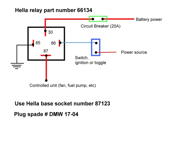
Relays are really simple if you can visualize them. Pin 85 is your switched power source (like your keyed 12V or your switch itself). Pin 86 runs straight to ground. Pin 30 is your power source, usually straight from the battery pos. Pin 87 runs to your accessory that you're installing. When you turn on power to Pin 85, Pin 87 gets power. If you're running a 5-Pin Relay, just ignore Pin 87a.
Unless you want something to recieve power when the switch is off...
Here's a diagram:

This is depicted with Pin 85 receiving power.
Unless you want something to recieve power when the switch is off...
Here's a diagram:
This is depicted with Pin 85 receiving power.
Nov 24, 2010 | 04:47 PM
#1622
I ran my ground to 85, since that's what the diagram I had told me to use, lol.... It works fine. It helped me to think straight, as this is all new to me, and so I just visualized "Power comes to 30, The Switch, on 86, flips it open to allow 87(the lights) to receive the power from 30. 85 is Ground, and I capped off 87A with a heat Shrunk sealed spade connector, then heated up the bottom half that had heat shrink sticking out and pinched it together... now it's totally sealed up, as are all the rest.
I was told I could have used either 85 or 86 for ground... I just used 85 because it helped me, like I said, make it more 'in order'.(I know, in my thinking, ...it was in order, hahaha.)
I was told I could have used either 85 or 86 for ground... I just used 85 because it helped me, like I said, make it more 'in order'.(I know, in my thinking, ...it was in order, hahaha.)
Nov 24, 2010 | 05:27 PM
#1623
Thread Starter
Registered User
iTrader: (2)
Joined: Apr 2010
Posts: 4,835
Likes: 3
From: Walnutport, PA
I ran my ground to 85, since that's what the diagram I had told me to use, lol.... It works fine. It helped me to think straight, as this is all new to me, and so I just visualized "Power comes to 30, The Switch, on 86, flips it open to allow 87(the lights) to receive the power from 30. 85 is Ground, and I capped off 87A with a heat Shrunk sealed spade connector, then heated up the bottom half that had heat shrink sticking out and pinched it together... now it's totally sealed up, as are all the rest.
I was told I could have used either 85 or 86 for ground... I just used 85 because it helped me, like I said, make it more 'in order'.(I know, in my thinking, ...it was in order, hahaha.)
I was told I could have used either 85 or 86 for ground... I just used 85 because it helped me, like I said, make it more 'in order'.(I know, in my thinking, ...it was in order, hahaha.)
 Nov 24, 2010 | 05:55 PM
#1626
Registered User
Joined: Jun 2005
Posts: 98
Likes: 2
From: Mt. Hood, OR / Ft. Leonard Wood, MO
Nov 24, 2010 | 07:33 PM
#1628

Registered User


Joined: May 2008
Posts: 523
Likes: 1
And the coil in the other picture is just the thing inside the relay that makes it work. Think of it as a referenced switch. When it sees power through 85/86, the coil turns on (switch turns on) and allows power through 30 to 87.
Nov 24, 2010 | 07:59 PM
#1629
1. Power wire from lights(Positive) to #87 Pin(You join those 2 wires together onto a 10G wire,then onto #87 Pin).
2. Ground wire from lights(Negative) to Frame(I used the Cross Member, there are tapped holes)
3. Power supply to relay(which also powers the lights) goes from Battery to #30
4. Main Fuse goes between Battery to #30 Pin and should be no more than 12" from the Positive Battery Term.
5. Relay ground goes from #85 Pin to somewhere very near by on body
6. Switch gets wired to #86 Pin and Driver Kick Panel Fuse Block(I used an Add-a-line in the Ignition Fuse Hole---bottom right---Ignition fuse goes back in the add-a-line closest to the fuse block and 10A fuse can go on outer fuse hole on add-a-line)I used the Ignition fuse because that way, the lights CAN NOT be left on with the key switched to OFF or just plain out of the key hole.
If you look at my build thread, Brian, I put pretty good pictures of everything, just for that reason.... because I'm just learning electrical, for one....and secondly, I like visual aide! lol.
Nov 24, 2010 | 08:24 PM
#1630
Nov 25, 2010 | 04:33 AM
#1631
Registered User
Joined: Aug 2009
Posts: 13,574
Likes: 72
From: Wilkes-Barre, PA, USA
you all beat me to it lol.
or you can check in with Chef's thread, he just did his, even though some of us were not 100% accurate I guess. But his is working. lol
BTW, I still have to relay mine up. Only thing I have been waiting on is a good fuse block, because I got too many accessories as I sit now. haha. ie CB, associated CB linear amp, Stereo amp, Fogs, and "upgraded" headlight harness.
Only thing I am gonna do alot different is retrofit a deck lamp switch from a 4runner as my fog switch. I just got to fine a diagram of the wires lol. Haven't been looking to hard for it though.

Last edited by xxxtreme22r; Nov 25, 2010 at 04:37 AM.
Nov 25, 2010 | 12:33 PM
#1633
Registered User
Joined: Jan 2008
Posts: 562
Likes: 1
From: Sacramento Valley, Ca
yes, that's part of the beauty of the 12v systems on a vehicle. The metal body acts as the common ground. Thus your negative battery cable is attached directly to the chassis (body) of the vehicle.
Nov 27, 2010 | 08:54 AM
#1635
Registered User
Joined: Jan 2008
Posts: 562
Likes: 1
From: Sacramento Valley, Ca
But if whatever your attaching to, ie a bumper or roof mounted lightbar, isn't bolted or welded directly to bare metal you likely won't get a good ground and may want to either clean off the paint at one of the points of attachment or better it to run a ground wire back at least to a known good grounding point. Just a little food for thought.
Your Rig looks great to by the way!!
Your Rig looks great to by the way!!
Nov 27, 2010 | 12:58 PM
#1636
Thread Starter
Registered User
iTrader: (2)
Joined: Apr 2010
Posts: 4,835
Likes: 3
From: Walnutport, PA
But if whatever your attaching to, ie a bumper or roof mounted lightbar, isn't bolted or welded directly to bare metal you likely won't get a good ground and may want to either clean off the paint at one of the points of attachment or better it to run a ground wire back at least to a known good grounding point. Just a little food for thought.
Your Rig looks great to by the way!!
Your Rig looks great to by the way!!
And thanks man!!
Nov 28, 2010 | 09:21 AM
#1639
Thread Starter
Registered User
iTrader: (2)
Joined: Apr 2010
Posts: 4,835
Likes: 3
From: Walnutport, PA
haha exactly!
Updates hmm lets see, got a new radio surround and hood bug deflector and altimeter hood from Wyoming09. I helped him at his shop a little bit. And the truck is going in to the shop next Friday.
Updates hmm lets see, got a new radio surround and hood bug deflector and altimeter hood from Wyoming09. I helped him at his shop a little bit. And the truck is going in to the shop next Friday.
Nov 29, 2010 | 09:59 AM
#1640
You got a tilto-altimeter for the dash? If so, cool...There's quite a few threads if I remember right on installing them. Not sure you'd need that.......and not sure that's what you got, ..OH FORGET IT! lol, hahaha.
And, ......going into the shop for what?
And, ......going into the shop for what?


