When you click on links to various merchants on this site and make a purchase, this can result in this site earning a commission. Affiliate programs and affiliations include, but are not limited to, the eBay Partner Network.
I'm guessing he made it with a label maker. Best mod I ever did was buy a label maker when I bought my 4Runner. It is a must for anyone doing mods, electrical especially. I bought a Brother P-Touch 1230 because you can hook it to a PC and print anything you like.
That is a good idea. I am always having to look on the tire for the air pressure. I have thought of a stencil and some paint on the inner fenders. Not sure how long it would last. Great idea.
I ran the second light in the pickup truck rear view mirror light combo, and rent it off the dome so that I had door/on/off capabilities and obviously so they go on the same time when I open the doors. I'm not sure exactly what you were jumpering into, I guess I need to read more. Anyhow, the dump circuit wiring runs up the driver side a-pillar and back and across to the dome. Actually it's easier just to show you with pictures. I can't remember exactly how many I took when I pulled the headliner... The reason I did so is because not only did I have to run that, but I ran all of my roof rack lights up through the headliner above the oh s*** handle and all that, and then across that funky reinforced beam or the dome light sets.
Okay, for your antenna... I ran that small cluster of wires up the a-pillar to feed my roof rack lights and it was an absolute pita! But I eventually got it and it was well worth it to do a clean install. As far as the antenna, if you're trying to do something sandwich between there, I'm assuming a European style or otherwise? Well, I'm sorry to tell you there are no holes that go through. The shell mounting holes are it and they are fixed Nuts which you really don't have any access to/can't really go without, without risking seepage.
If you are talking about the CB radio antenna, which I really doubt that you are, I highly recommend doing what I did and mounting it somehow to your rear bumper, then fixing it along the seem of the tail light and show. You could probably mount a tab coming of the rearmost bolt of the shell that would allow you to secure the top half of the antenna. With a four foot whip it should come perfectly level with the roof, maybe a little taller. You would have to install a separate ground style antenna mount, but there are so many out there that work really well. I have excellent reception was mine mounted to the bumper, and you could ask Jonny boy or Richard.... For a 75WXST hardmounted handheld mine is really clear. Even if this is just for future reference, trust me, my antenna is never in the way and using a heavy duty spring and forefoot whip, I have incredible resistance to smacking around and so on. I have a tennis ball on it now and not actually looks pretty good being that its a red one! Lol. It keeps it from bouncing off of the body as much and doesn't allow it to get to its full articulation of spring bounce.
Oh yeah, by the way, my wiring that went through to the roof rack was accomplished by drilling a hole in the top of my roof. It's the cleanest way to do it and not have wires exposed to the elements. Since I'm guessing you do not want any holes in your roof, if you are thinking about possibly mounting that antenna on the middle, there might be a good area behind your head on the passenger side towards the passenger door from the dome light. Or actually is access to the roof even if you have a summer. Trust me, the sunrise makes it a much bigger pain in the butt. But the good thing about a sunroof, you could make a little bit of grinding around the outer seal of that window and work the small wire for an external antenna mounted flat on the roof very simply without compromising the seal.
Hi Terry and Mark,
I just need to run coax cable for antenna from passenger side A-pillar to the fiberglas cap. Antenna is strip type - kinda like the LED light strip. I will sandwich it between fiberglas rof and headliner.
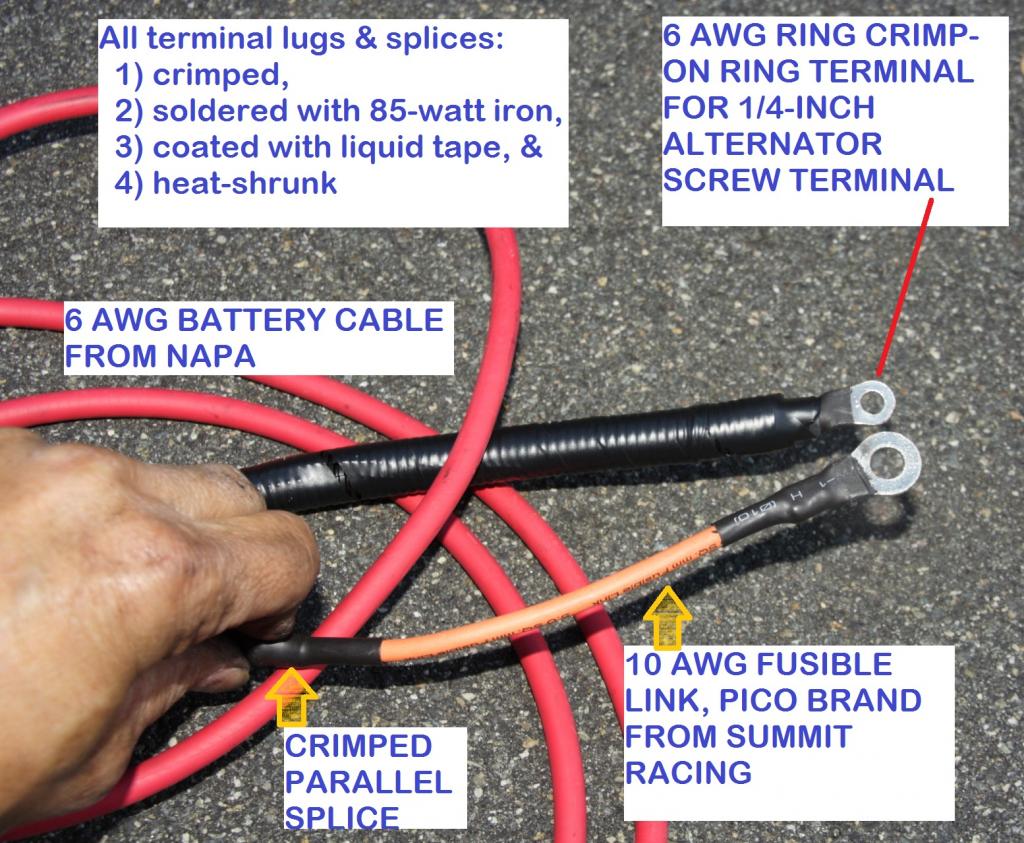
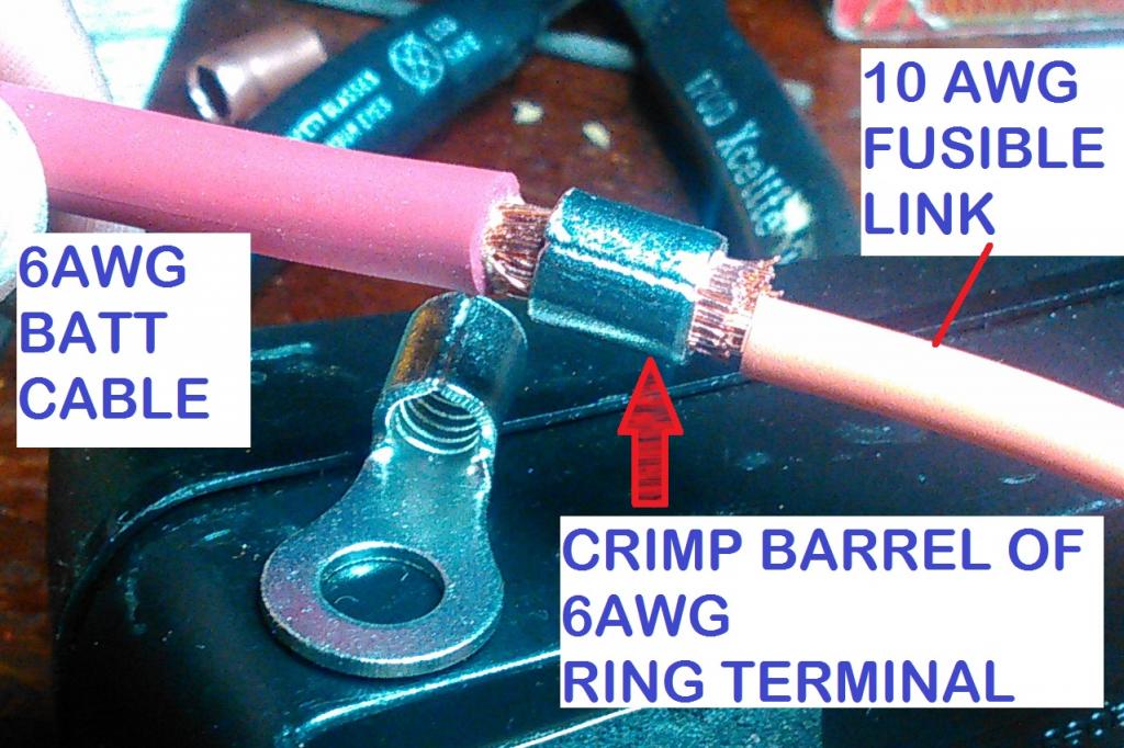
I had a hard time finding a parallel crimp connector for splicing my 6-AWG upgrade "B" cable to 10AWG fusible link.
However, it turns out that the crimp barrel for the 6AWG heavy-duty ring terminal from NAPA fits.
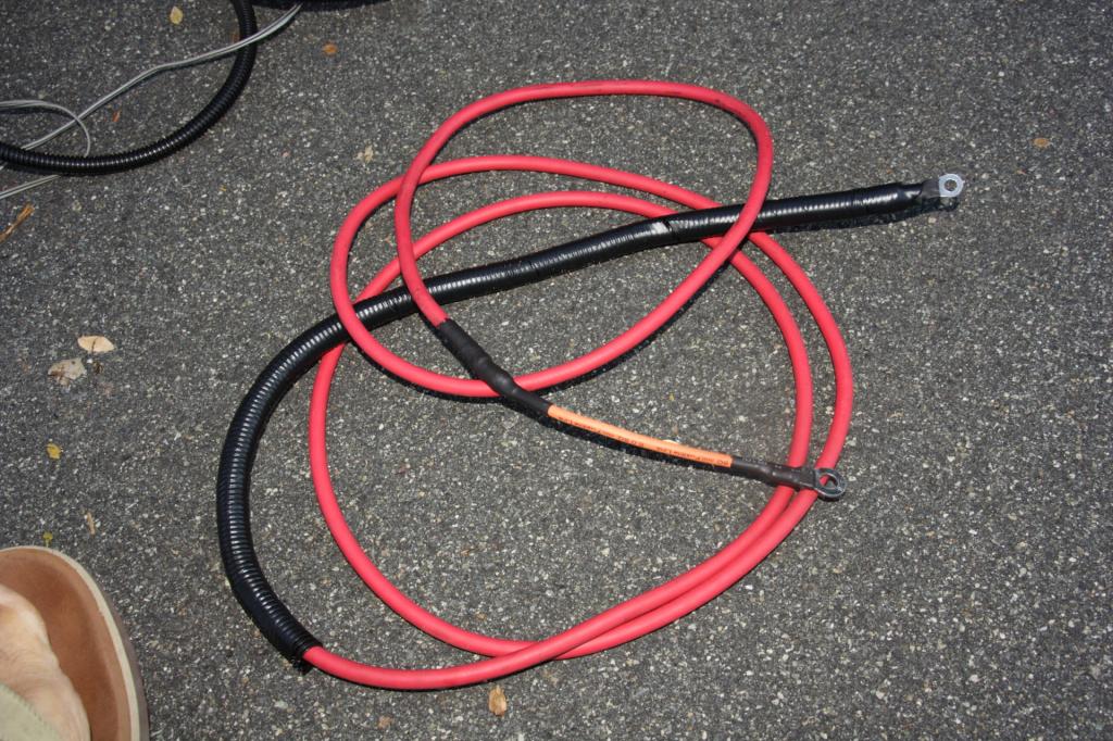
I already made the upgrade "B" wire. Just waiting for time to install. I wire it exactly like Mark wired his:
Disconnect stock "B" wire from alternator post.
Connect Alternator post upgrade "B" wire, to fusible link (Mark used a 150-amp fuse), then to battery. Updated my Alternator Wiring upgrade post here.
Last edited by RAD4Runner; 12-10-2014 at 05:47 PM.
I upgraded to 90-amp alternator. Here's the final schematic for upgraded "B" (alt-to-batt) wire... Funny, that Redeth called me as I was working on mine. Connection below is exactly same as Mark's (Chefyota) and Richard's (Redeth), except that the latter two used different wire gauges and circuit breakers/fuses to match their alternator outputs. This setup addresses worst-case scenarios discussed on my earlier post HERE. NOTE:You would have to find out what size "B" wire and fusible link to suit your alternator output.
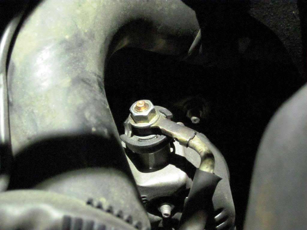
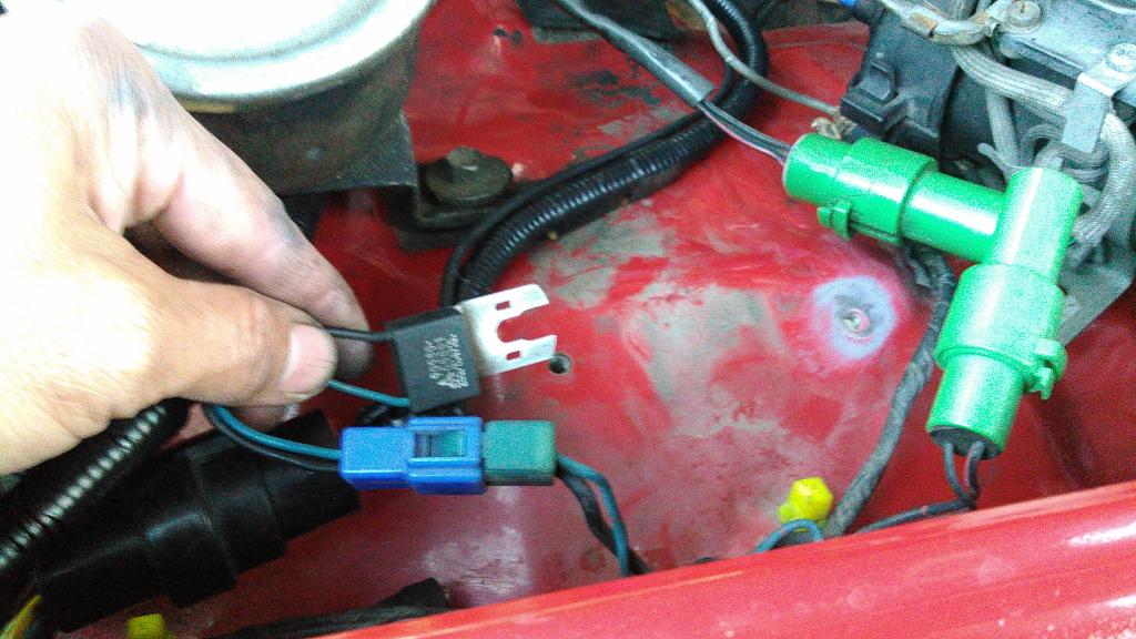
I disconnected the stock "B" wire from this terminal post (below)...
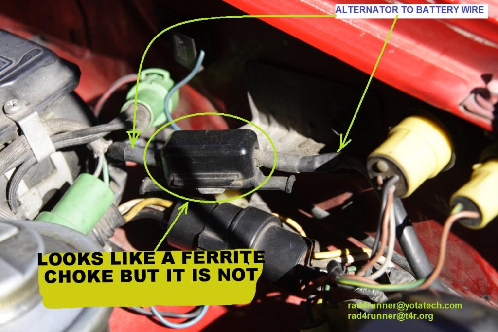
I removed this disconnect that merely takes up space and is simply another potential place for corrosion to happen ( pic here)...
... traced stock "B" wire all the way to the fuse block, and removed it. There are two other white wires (part of fuse block wiring), I re-connected them back to the screw terminal where the "B" cable was connected.
NOTES:
1) Leaving stock "B" wire connected would bypass the fuse block. Not safe.
2) You would have to figure out what wire and fusible link gauge to use for your own alternator capacity.
I then replaced the stock "B" wire with a single, continuous length of 6-AWG wire from NAPA, parallel crimped to 10-AWG fusible link from Summit Racing, then to battery.
I could not find parallel crimp connector for 6AWG and 10AWG combined at reasonable price/quantity, but found out that the crimp barrel of the 6AWG terminal lug fits.
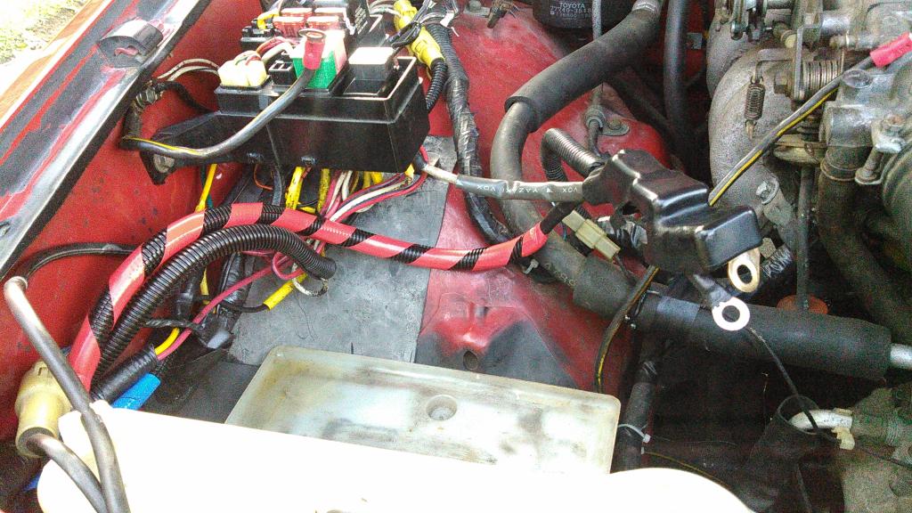
New "B" wire is protected with flex conduit from the alternator "B" post all the way to the battery connector.
Note that removing that disconnect, that I call an "appendix", and removing the entire stock "B" wire (If you are confident with your wiring skills) leaves everything cleaner and reclaims real estate (i.e., for future auxiliary circuits fuse block).
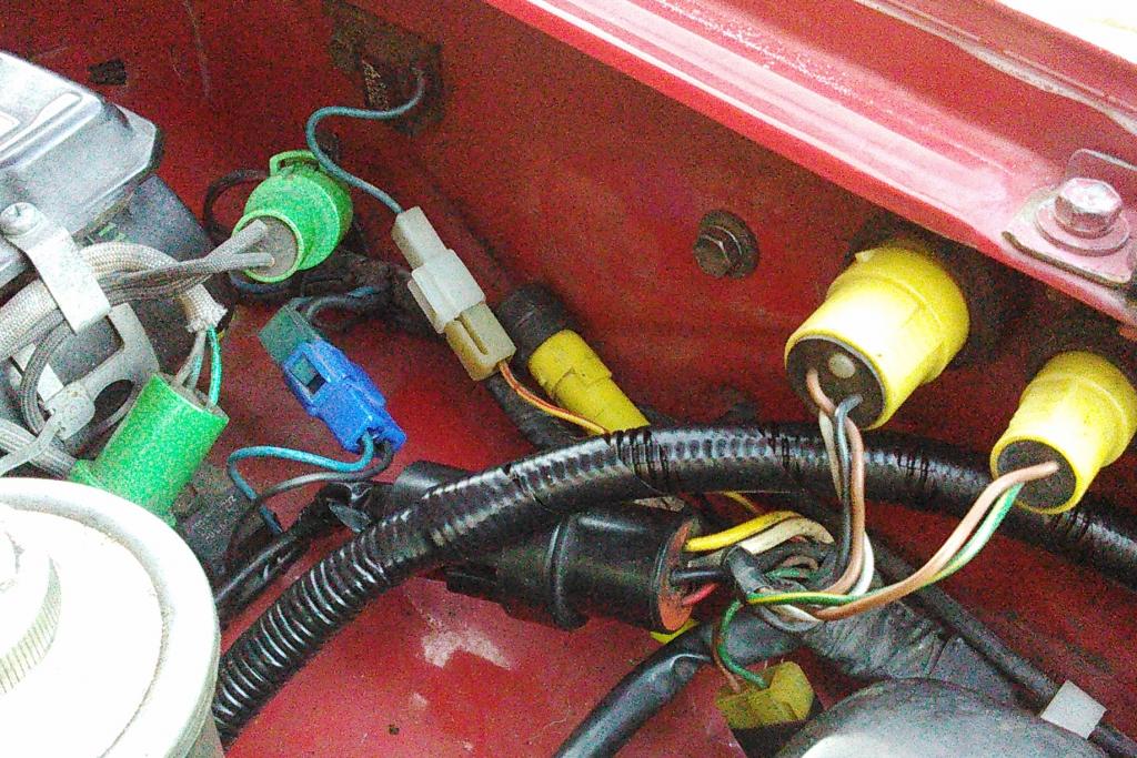
Before it was crowded here:
After... clean, available space and mounting for auxiliary fuse block:
I also relocated this component (a capacitor? Screwed down with the bracket for ignitor coil) to a hole farther back (closer to clutch reservoir) to clear the space for future fuse block. Also note that I cleaned ground connection down to bare metal, then coated everything with dielectric grease to prevent future corrosion.
That black wire grounded to power steering bracket is actually not part of charging circuit. It is ground wire for the noise suppression capacitor for the ignitor. In my case, because I eliminated that intermediate connector in photo, I simply ran to firewall ground near rear cylinder head.
Posting this on my own thread so it's easy to find...
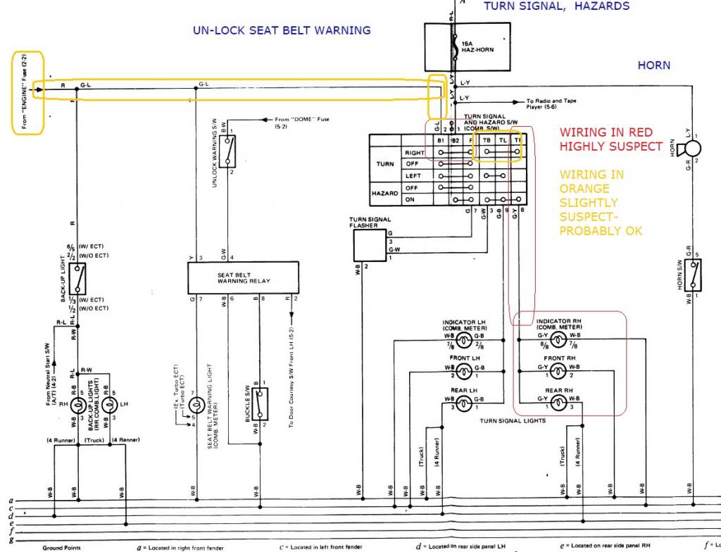
How Turn Signals and Hazards Work. Schematic is for 22RE but other years may be same.
Schematic is below but please ignore the red and orange notes - This is for the 1988 MoreFunner - wire colors may vary other years, but system works same way
Hazards take power from Hazard/Horn fuse, so can come on even with ignition off.
Turn signals take power from engine fuse, so will work only when engine IGN is on.
When hazard is on, or when turn signal is on, either left or right, you should see steady voltage at pin 7. This power goes to Pin 3 of flasher. Flasher will click. You should get alternating on-off 12V at Pin 1 of relay (Green-White).
When turn signal is on flasher relay will click,
At Right turn, Contact TB is connected to TR. you get power at PIn 8 (Green-yellow)
At left turn, TB is connected to TL. YOu get 12V at Pin 9 (green-Black).
With hazards on,
Three bottom right contacts connect both left and side signals to pin 1 of flasher.
Last edited by RAD4Runner; 12-15-2014 at 11:03 PM.
Anytime I work with the electric system, dielectric grease in nearby. Even spending some time with a brass brush or a pick and cleaning the connectors seems to help a little bit.
How you liking the 90 amp alternator? It has got to be an improvement. Probably something I am going to do when I need to replace my next one.
Hi Terry,
The Alt's working well now, although it's pretty hard to compare with the old one because I haven't done any real load testing. I guess we'll find out when I add lights.
Last edited by RAD4Runner; 02-25-2015 at 02:36 PM.
Ray - sorry if it was posted already, but which 90 Amp alternator did you purchase? Absolutely love your detailed writeups.
Hi Cory, absolutely no problem. It was from AES electric from san diego. Supposedly stock housing with upgraded rotor. No way for mw to verify, however. A search for aes electric san diego wud yield couple of results including one on yotatech. However, i suggest u look at marks (chefyota) build. He got 140-amp plug n play, i believe
For that, i'd use thicker wire, wired like his, mine and richard's (redeth).
Happy new year!
Last edited by RAD4Runner; 01-01-2015 at 10:12 AM.
Problem:
Non-power whip antenna gets in the way of loading 13-foot kayak on roof and is one more thing to worry about in the car wash. I do not want a power antenna because it's one more thing to break. I want minimal moving parts, simple, reliable, inexpensive - same reason I picked the 22RE MoreFunner.
Solution: NOTE: NOT RECOMMENDED FOR TRUCKS WITH METAL ROOF. Metal roof will suppress radio signal
FM Reception was poor when antenna is placed on dash. AM reception; NADA. Too close to metal/ground, so...
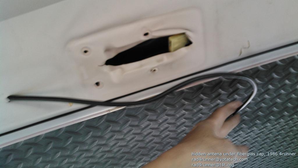
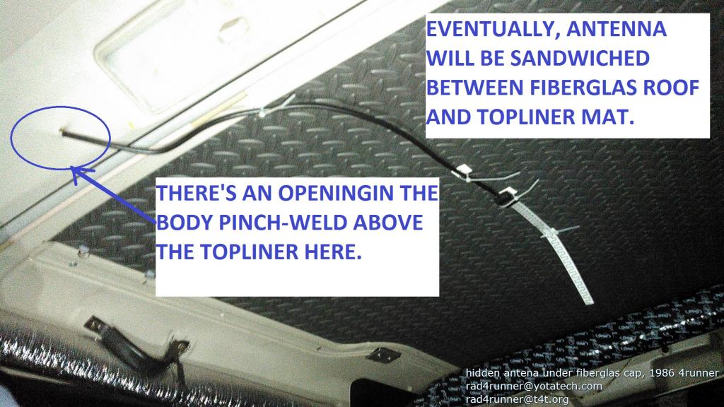
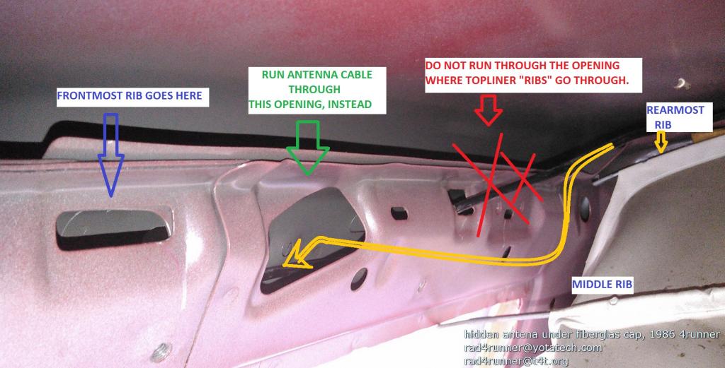
I ran the cable through through the opening in body / pinchweld above the topliner near dome light...
Mounted on Fiberglas cap topliner (I will eventually move it so it is sandwiched between Fiberglas cap and topliner mat). NOTE: NOT RECOMMENDED FOR TRUCKS WITH METAL ROOF. Metal roof will suppress radio signal.
Ran it in the channel above the door. I had to correct mistake I made of running it through opening where the rib goes in.
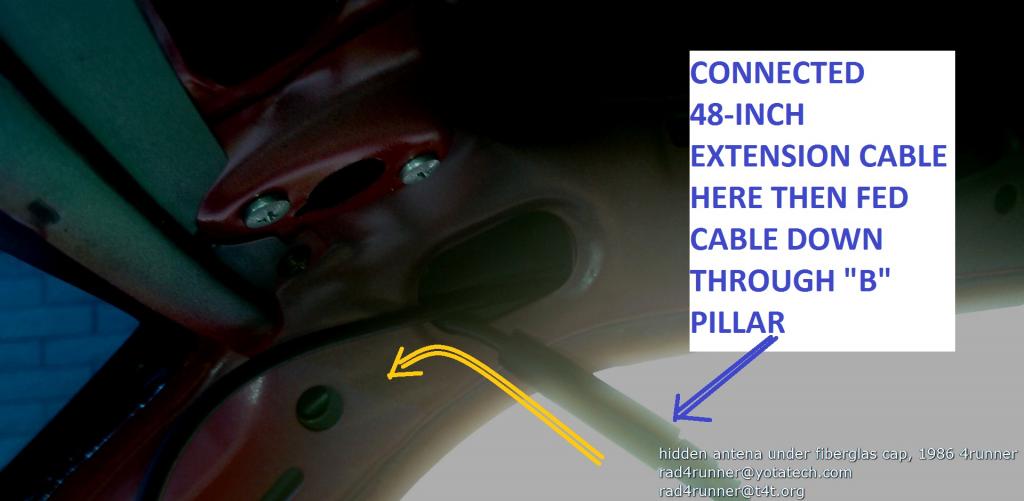
I added a 48-inch extension cable ($5.61 at OReillys) here...
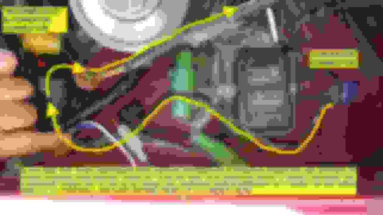
Ran it inside the A-pillar to an opening behind the ECU, then eventually to the radio...
UPDATES, 05March2015:
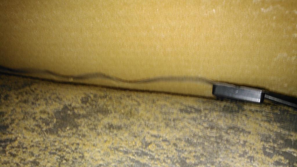
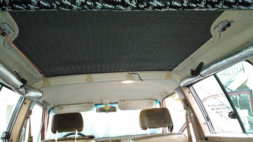
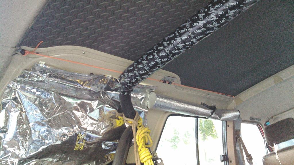
Sandwiched antenna between roof and diamond-plate pattern headliner. Brown material below is original headliner foam. Grey material is the close-cell, diamond-plate pattern anti-fatigue mat I'm using as headliner.
Antenna now hidden above the foam headliner:
Note Orange Cord attached to wire clamps secured by roof rack mounting screws:
Results:
Good FM Reception, Decent AM reception.
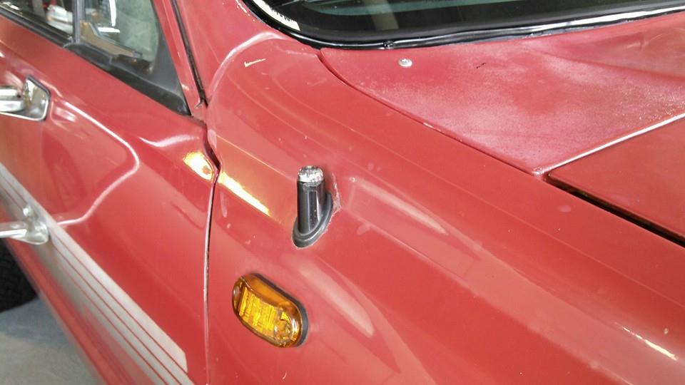
No more antenna rod sticking out of the fender....
If Anyone is interested in the stock antenna assembly, including the whip and cable, I'll sell it for $20 (local pick-up only). The mounting nut alone for the antenna base is $12 at the dealer.
Last edited by RAD4Runner; 03-05-2015 at 06:24 PM.
Reason: I meant "A" Pillar

 12-05-2014, 05:24 AM
 exactly like RBX did and have. Great tool to have. And tape is UV- resistant. Label evrything.