When you click on links to various merchants on this site and make a purchase, this can result in this site earning a commission. Affiliate programs and affiliations include, but are not limited to, the eBay Partner Network.
I continued the replacement of my parking brake cable.
Not a fun job, lots of cramped spaces!
I only want to vent about rockauto having the wrong part. The description and vehicle fitment say the right things, but the the cable actually does not fit. Not even close. See the pics. Its way to short and the rear/bottom end is not correct type.
This is incorrect end type You can see length difference
Also, today I removed one of the two transmission oil coolers I had installed a while back when I was trying to keep my tranny cool! I came to the conclusion that the one I installed at the bottom (behind the brush guard) with the fan is not doing ENOUGH for the space it is taking. That location is just not proper for good air flow. The thin hayden one I added behind the grill is what made a big difference. So, I just ordered a new hayden radiator that is a little larger since I have a little bit more space behind the grill. It should fit and will make up for any cooling that this other cooler was doing.
Also, I drilled out and re-threaded the 4 bolts holding the brush guard up. No matter what bolt i put in there the threads would get screwed up! Not anymore This was my first cooling install experiment.
Hi folks.. SO, I had purchased wheel spacers some time ago. I was torn about it really, so I let them sit around because I haven't been a big fan of spacers. I thought I'd just get a 1/4 spacer, that would leave me plenty on the studs still.. But, I figured I am not gaining much with 1/2" total extra width.
So, I reevaluated why I wanted spacers in the first place.
1. Been on plenty of un-even trails that feel a bit scary, so a wider footprint would help in stability.
2. Looks, especially with the narrow tires I recently installed... The car looks really tall because it is soo narrow.
3. Softer suspension due to additional length of 'lever' action. Here I am not so worried about ride comfort, but I think this makes my car a better offroader by rolling over obstacles...
I decided I am gonna go for it, it's mostly reversible anyway, just remove them. I do have to cut off almost a 1/4'' of my lugs though... Didn't like that part much..
ANyway, installed... and I think the truck looks much better. I will take a better overall picture during the day.
With spacer.. It's hard to see the difference in the pics. Without spacer
So, I stole a few hours one day and wasn't feeling great so stayed home today... But I was well enough to tinker.
I had been thinking about a roof rack for a long time. I started the roof rack planning a few days ago and part of that was repainting the roof. My buddy vaptor lined his entire Jeep xj in blue and I was impressed by the quality and aesthetics, not to mention the ease of installation!
So, I sanded and prepared the 29 year old roof paint. With his help we taped and sprayed!
This is after couple runs of sand paper Taping. Was easier than I expected
Then The rook rack:
My initial idea was inspired by something I saw here on yotatech a while ago. I wanted a slim and as lightweight as possible design. I purchased struts and put it on the roof and thought and pondered.. Then decided I didn't like the look of it from the sides.
I went to a metal supply place nearby and walked around a bit and eventually formed my new design in my head. Purchased some pieces and hurriedly came home to get started! I will use the pictures to write the rest of my thoughts.
I got some 3x3 angle aluminum pieces. Aluminum being less nice than steel to bend in the garage, I had to plan the whole design with no bends. I used cardboard to layout the ideas in my head to see what it will actually look like. This was my initial idea for the rear. It took me a lot of thinking to decide on the length. I have purchased a 43inch LED bar for the front and two 6 inch LED bars for the rear. I used the desired final location of the lights to help decide on the length. Then came 4 hours of effort that I eventually scrapped and started all over from total scratch. I mocked up several mounting brackets from angle pieces available in stock at nearby stores. I didn't like any of them. I purchased some 6 inch wide by 3/32" thick sheet metal and fabricated all the mounts from scratch. I decided bending will never look as clean and be as precise as I want this project to be. So, cut and weld! They are all tacked in these pics. Used clamps religiously to clamp and temporarily place the parts in place to make sure all the hole lined up and everything is square and flush and looks good! What it is going to look like when mounted. Checking level and placement. Although I didn't have countersinking bits for steel, I decided I will make some countersunk holes anyway for a flush look. Minor imperfection will be well hidden once I raptor the completed roof rack.
Next. mounting the rear led lights. I wanted a slick look.. boy.. fabricating for a slick design is time consuming .. Some time later I had the cross bar (the unistruts are perfect for this!) Brackets to mount unistrut to aluminum rails. Using aluminum as much as I can to keep weight down. Fabricated parts loosely fastened in place for test fit. This is what it looks like from the rear. The front and rear points of the rails are higher off the roof than I really would prefer. But I am limited by the height of the center of the roof. When you put a level at the center, this is how high it gets at the rear. I needed the surface of the roof rack to be flat so I wasn't about to curve the rails.
The cross bars will be flush with the top of the rails. This took me some time to decide, but, I do construction work sometimes and if I throw some long lumper on the roof rack I want the weight to spread all over, not point load the front and rear rails. Also, this is a good shot of the raptor liner. Love it!
That's as far as I got today. I was hoping to have all of the parts fabricated and ready for prep and paint. I am about 4 hours behind that schedule. lol. Not to mention the front LED bar by CaliRaised is on back order
I wasn't feeling great today so I decided to leave the high energy and loud fab work of the roof rack and fix my intermittent start issue. Now I had followed this problem over the years on this forum and I knew of Rad4Runner's fix and his ability to understand these wiring diagrams. Unfortunately for me his vehicle is quite different than mine in the details. That coupled with the uncertainty of which years have what wiring design and on top of that the uncertainty of which wiring diagram applies to my actual car (since I have not been able to find a service manual that is specifically for 1991 August manufactured 4Runners...)
However, I am confident in my troubleshooting skills and my wiring diagram reading abilities. On top of that the overall design of the 'fix' as seen on these forums made a lot of sense to me so I knew what the end result was. With that, I'll start my ordeal and findings from today.
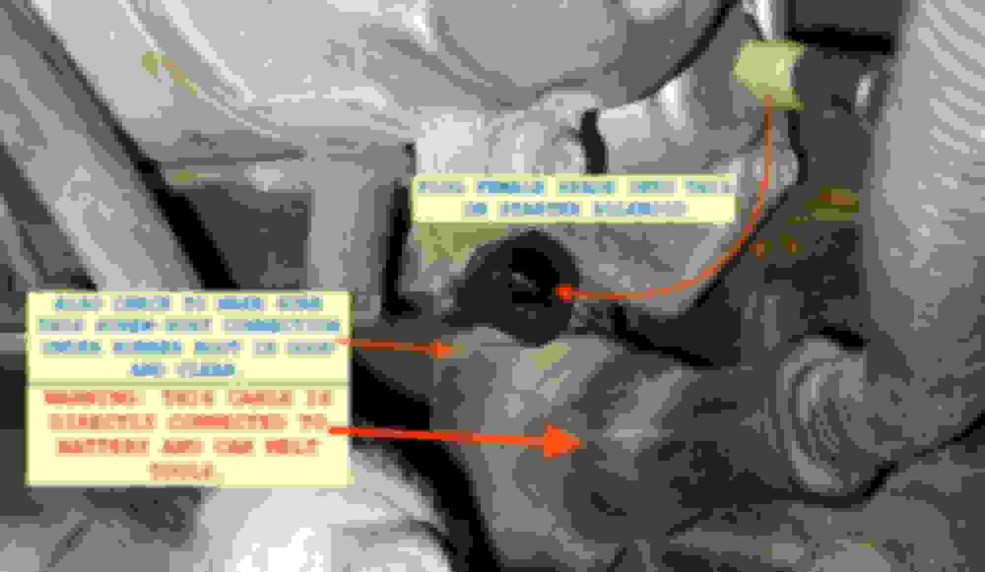
I started by assuming that my system was also around 12 amps draw on the starter solenoid, this will later prove to be an incorrect assumption. I also assumed that the single black -white wire from the starter solenoid ran straight without being spliced into from the starter to where I opened the loom in the engine bay, this also was later proven to be incorrect. I will mostly use the picture to write the rest of the story. (EDIT::: I used information from Rad4Runner's build thread and later I found the thread I was actually looking for. In this thread he notes the amperes and wire gauge that apply to my case ---> https://www.yotatech.com/forums/f116...runner-307493/ )
In this picture you see where in the engine bay I found the Black-white wire, which I incorrectly sized up to be 14 gauge based on my incorrect assumption that the solenoid is using less than 15 amps. I believe now that this wire is a 12-gauge. As I cut the wire I decided to test the starter circuit at this point expecting fully that nothing will happen, only the starter relay will click. TO my total surprise the solenoid clicked, and clicked and eventually after few tries the starter turned over. I was very confused, so I started to figure out why through the wiring diagrams. I made a little video talking about it as it was much easier than trying to refer to an image of it. I'll share that after this picture. Meanwhile, I tested a couple of things. I put my multimeter on both ends to see what is happening to the voltage and to understand what direction the voltage is coming from. The left wire in the image continues down and seems to join another loom of wires before exiting the bottom as the single black-white wire to the solenoid. That wire has 9 volts in it when the ignition is turned to on (BUT NOT STARTER ENGAGED POSITION)
Here is the proof...
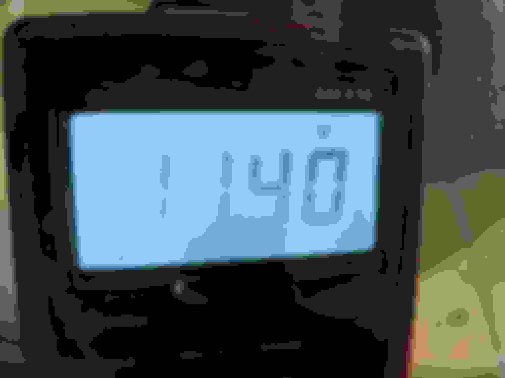
THen when the starter circuit was closed )i.e. key in starter position) the voltage in the same wire was.... see pic..
The other side had 0 volts when ignition key was turned to 'on' and just under 12 volts when key was turned to starter position. The interesting thing is my battery is at 12.5 volts, so 11.0 volts is a massive drop just in wiring! I never did test the voltage at the solenoid in stock position, I assume its an average of the 11.4 and 11.8.
sorry I realize my video is slow. Need to practice? Lol
https://youtu.be/PG-lfbLPG-lfbLcpC
If you don't care to watch the video, I conclude by noting how I did my fix. I intercepted the wire down in the guts right before it plugs into the starter solenoid, extended it to the engine bay, connected it to the low power switching circuit of a 30amp relay and ran a wire from the high power output of the relay to the solenoid. So, now the starter circuit is exactly as it was except it is just powering a low power relay instead of the starter solenoid. Ofcourse then the relay is powering the solenoid with a direct line from a 30 amp fuse near the battery.
Earlier I mentioned I incorrectly assumed the solenoid draw was 12 amps. Rad4Runner has written in his thread that so I figured it's where I will start. As I completed this fix I had a 15 amp fuse in the fuse block feeding the high power side of the relay. When I went to start I got the dreaded click again, I was really confused. I clicked again and again and on the 4th click the starter engaged and promptly the 15 amp fuse blew. I thought, well..... either I have diagnosed my start issue incorrectly and it is actually a bad starter (which I doubt because I had this problem with a pretty new Napa replacement so I put the starter off the 1995 doner I had and same thing and it's been getting worse). I changed the fuse to a 30 amp and tried again. I got a solid starter engagement and was happy. BUT, I believe once the engine turns over the intermittent start issue is less likely to happen right away. So, time will tell. If it turns out to be my starter atleast I now know won't be having the wiring issues in the future
I will try in the morning if I'm not running late to work and see if I get a click or not. Additionally, earlier I said that I incorrectly assumed 14 guage wire will be sufficient, well it isn't. I made that assumption based on being under 15 amps, but at 30 amps I now have to increase the wire to a 12 gauge. I will do that before I put the wires in a loom and secure it all. For now I made it this far
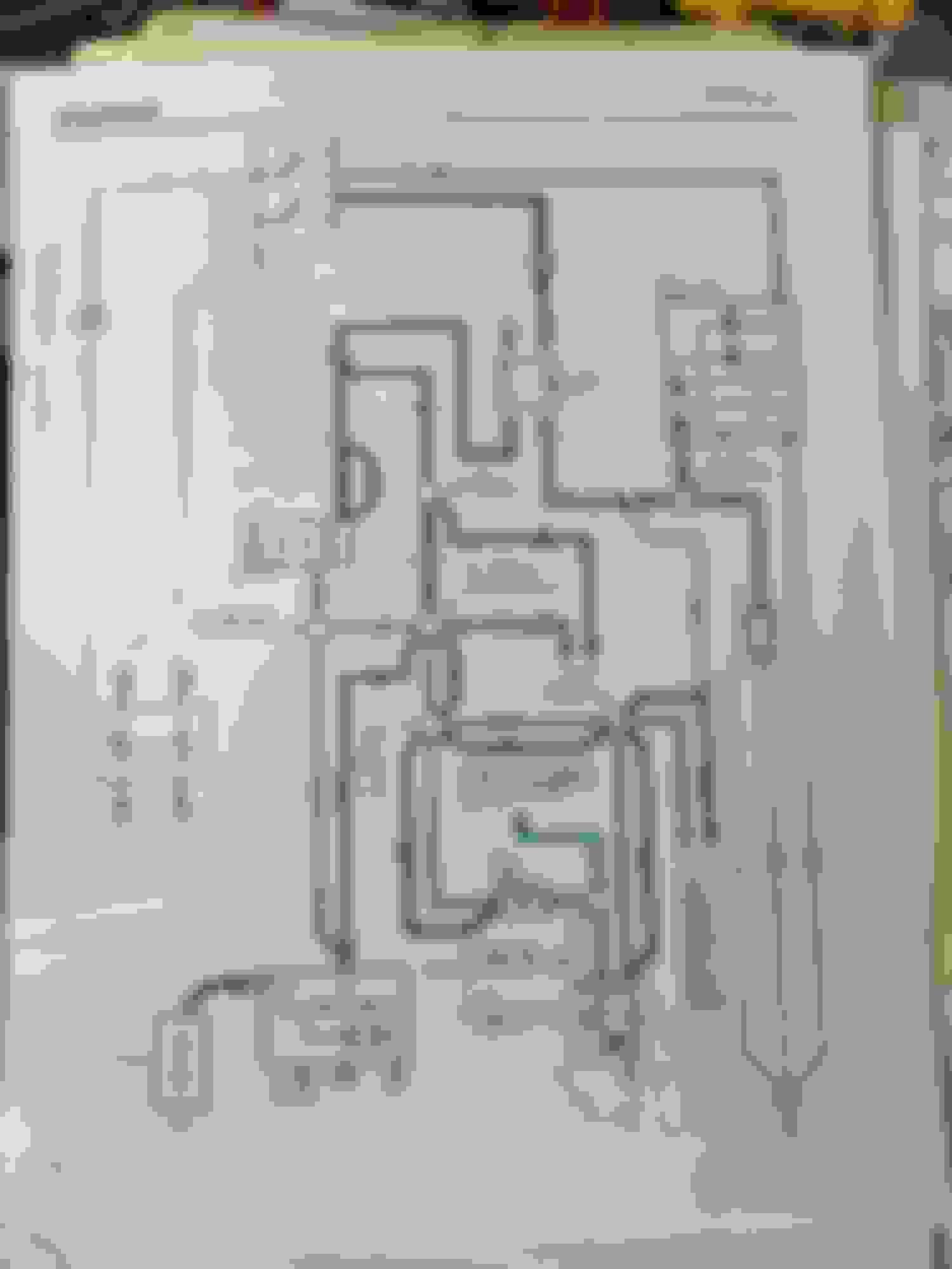
This is the wiring diagram I found that I believe relates to my car. I found several that didn't make sense so I concluded they are either not the correct model year, engine or tranny configuration. Some of the diagrams didn't show these details.
Nice more-than-start on the roof rack and the roof looks good. Good luck on the wiring, those nice neat wiring diagrams always turn into spaghetti in my brainium.
Don't get too tied up on wire gauge. If you do house wiring (in the US), the National Electrical code requires 14ga wire for 15amp breakers, 12ga for 20amp breakers. This has nothing to do with automotive DC wiring. The voltage drop in 2 feet of 14ga wire at 15amps is less than 0.2 volts https://www.rapidtables.com/calc/wir...alculator.html . A brand new, fully charged battery will have that much difference in voltage between a warm day and a cool day. Switching to 12ga wire would make about a 0.05v difference; that's not your problem.
I'm surprised, but not too surprised, that you're blowing a 15amp fuse with the solenoid draw. This guy says 8-10amps http://www.aeroelectric.com/articles/strtctr.pdf, Rad4Runner says 12, and you're blowing a fuse at 15. I suspect that all of you are correct; Toyota "protects" the solenoid circuit through AM1, which in '93 is a 40amp fuse. Fuses are designed to blow very quickly (much faster than circuit breakers), so Toyota expected that you might get a tiny high-current spike in there some times.
Last, I've seen a few posts lately where people talk of the "high-voltage" side of the starter relay system. The only "voltage" you have at your disposal is battery voltage (about 12.6v for starting, about 14.1v when running, due to the alternator), and it's the same on both sides of the relay. What you really mean is the "high-current" side. The solenoid draws 8-10 or 12 or 15amps, which you want to keep out of the ignition switch. The relay coil pulls about 100-500ma (0.5amps), which is much easier on the ignition switch and all the connections along the way.
Nice job mounting the new relays. I'll bet it works fine as is.
Yes yes, I tried to refer to the high current side as 'high powee' side. My apologies if I referred to it as voltage.
I checked the charts for 12 v DC circuit and I will definitely be going to 12 gauge on the high current wire. I did not really consider the voltage drop difference across the 14 or 12 gauge. I just quickly estimated that the 11.4 volts is less than would be just due to the voltage drop across wires. But, now that I have seen how convoluted the wiring is... And there seems to be a lot of wire in this black-white circuit; it probably is due to old wires and many feet of it.
I was very surprised about the 9 volts though.. is that by design or is it a problem in my wiring harness. ???
I don't understand why you'd be getting 9v with ignition to on either, nothing in that diagram seems like it should have power unless key was on start. Interested to know if anyone else can figure it out though, or if it is an issue. On my '07 2UZ I had to install an air pump bypass recently and was surprised to discover the coil side of start relay had 6v at IG on and 12v at start. But that system is set up completely differently with the ECU feeding the combination meter along with the start circuit so I assumed it was by design from there, stray voltage that was powering something necessary at 6v which wouldn't be enough to activate the relay. Never did find out for sure.
The IH1 connector in your diagram is one of the main body connectors used in a 3.4 swap, upper passenger kick panel area,relay before it is obv in the engine bay, the junction after it is back in the engine bay, so that gives you some idea how much spaghetti wiring there is in that circuit.
Well the black-white wire that goes all over the place connects to so many things that there is probably some voltage that makes it's way through somewhere. But, I don't see it causing any issues so I'm not about to chase it down!
Making a post just to share how happy and excited I am for my new tool!
I 'needed' only 3 of these really, but I wanted to spread the load as much as practical. I installed 4 for each side. Lovely lovely tool The first insert - This is the exact flexibility I needed for my roof rack install! The tool
Well the black-white wire that goes all over the place connects to so many things that there is probably some voltage that makes it's way through somewhere. But, I don't see it causing any issues so I'm not about to chase it down!
It does, if that diagram is correct and I'm reading it correctly, the only place positive should be coming from is through the start relay though. Other side of circuit open relay is grounded after the "start" coil I believe, which provides fuel flow when cranking, other side of cold start injector switch is grounded by ECU, and so on. My concern would be having something that close to a 12v relay's threshold voltage to overcome the spring and close the start circuit, meaning your truck could start with key to IG1. Maybe I'm missing something.
It does, if that diagram is correct and I'm reading it correctly, the only place positive should be coming from is through the start relay though. Other side of circuit open relay is grounded after the "start" coil I believe, which provides fuel flow when cranking, other side of cold start injector switch is grounded by ECU, and so on. My concern would be having something that close to a 12v relay's threshold voltage to overcome the spring and close the start circuit, meaning your truck could start with key to IG1. Maybe I'm missing something.
That is a good point... If I have 9 volts going to my new relay... and that increases eventually close to 12, the starter will engage when I turn the key to 'on' but not 'start'... Hmm...
My other problem is, I don't think the wiring diagram I ended up using is what my 4Runner actually has installed. It seems that my automatic tranny 4Runner has the manual tranny wiring diagram.. lol. I am confused.. I need to take a more serious look at this... lame
Happy 2020, folks!
Just trying to catch up on this thread. Been busy.
Originally Posted by Gevo
...It seems that my automatic tranny 4Runner has the manual tranny wiring diagram.. lol. I am confused.. I need to take a more serious look at this...
Yes, we should re-group and look into this. Like I say often, Earlier trucks and documentation seem like Frankenstein starting his career - LOL!
Please clarify:
1) The 5tarter sol3noid clicks energetically always but no crank, OR
2) The start3r r3lay clicks but 5tart3r 5ol3noid does not click or only clicks faintly.
If yours is an auto, you should not have the starter relay - which is big part of the problem.
If it's a manual tranny, it might have same wiring as JPL's with the green starter relay behind kick panel - a poor location for starter relay.
Why bad location? Because the high-current wire would be too long....
Please verify for us?
Also verify if 5tarter sol3noid ALWAYS clicks energetically, AND motor cranks when control conn3ctor (below) is connected directly to battery. This will eliminate doubt on solenoid contacts.
Last edited by RAD4Runner; Jan 7, 2020 at 07:42 AM.
RAD4Runner, happy 2020! Thanks for joining my attempt at this fix! OK, to answer you questions:
Before I go on, quick update. I tried to start the car yesterday after ofcourse installing my relay setup. The starter engaged, then disengaged on first attempt. Second attempt engaged and was fine. I chalked it up to weakened battery from the previous few days of work. Put it on tender and will try again today.
1) The 5tarter sol3noid clicks energetically always but no crank, OR 2) The start3r r3lay clicks but 5tart3r 5ol3noid does not click or only clicks faintly.
Option number two. I would rarely hear the solenoid click if it was not engaging the starter.
Yes, we should re-group and look into this. Like I say often, Earlier trucks and documentation seem like Frankenstein starting his career - LOL!
LOL.. Honestly, it's shocking to me that the wiring was overlooked and poorly designed when pretty much everythign else on these cars is so well done.
Gevo, If yours is an auto, you should not have the starter relay - which is big part of the problem.
Yes, 1991 3VZE Automatic. As I said earlier, August of 1991 is a special case where it's frankensteined by parts and designs from 1991 year and 1992 year. I am sure I have a starter relay. I can hear this relay click, but, I am 'pretty' sure it is in the passenger footwell area. lol. It is a much louder relay click than the new relay I installed.
Please verify for us?
I can't easily verify this.. This is a source of the confusion for me on this wiring setup vs. wiring diagrams that don't fit. In my posts above I write about how I have 9 volts in the black white wire on the left side (of the cut i made in the engine bay) when key is ON. and 11.4 volt when key is START. On the right side of the cut there is 0 volts until key is in START.
Also verify if 5tarter sol3noid ALWAYS clicks energetically, AND motor cranks when control conn3ctor (below) is connected directly to battery. This will eliminate doubt on solenoid contacts.
I have verified with 100% success rate when I engage the relay I installed in line, the starter engages. This I believe applies to verify what you are asking.
I am pretty sure that I have a design where my black-white high current wire is too long. And, somewhere something is bleeding 9 volts when key is ON. lol
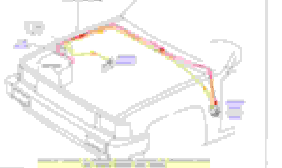
So of course I understand the wiring diagram below is not a 'scale' model... With that said, I have the following concerns about this wiring diagram vs. what I actually observe.
I have not seen the black-yellow wire splice into the black-white wire anywhere. This diagram makes it look like they come together at the male connector of the solenoid (point A), but it is not there. I instead have the Black-white which according to the diagram is for the MANUAL Trans. BUT this is the diagram for the 1990 to 1995 vehicles, so it should apply...?
Black yellow is for automatic transmission only if you have black-white you wouldn't have it - one or the other. I was assuming you had m/t. If your fsm has a range of years when downloaded it's usually for the last year listed, at least from what I've seen, best to find or download year specific (ideally diagrams from immediately surrounding years also, they don't always match model year) from that Toyota FSM site if you can.
I was under the impression you were getting 9v with your meter in series with the wire you cut. If you are grounding out one side and then the other it's possible that you were discharging a capacitor through it and that's where your voltage was coming from. If so it would likely drop slowly if connection was held for a few seconds.
I definitely have an automatic. lol And I definitely have black white NO black yellow.
The 9 volts were sustained for tens of seconds, for sure more than any system capacitor discharge time.
I will look for a more specific wiring diagram again. I'll try the autozone site, I was unsuccessful when i last tried.

 Oct 4, 2019 | 08:55 PM


 .. Some time later I had the cross bar (the unistruts are perfect for this!)