
BlazeN8's 1986 4Runner Build-Up Thread
 Jan 5, 2013 | 08:14 PM
#201
Thread Starter
Registered User
Joined: Jun 2009
Posts: 977
Likes: 4
From: Southern California
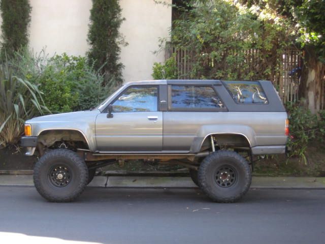
Well it came out with just about the right lift height. It sits about 3/4" of an inch higher now but the springs will likely settle a bit. Also the 4 Runner is not loaded with any cargo or even a spare tire.
Jan 5, 2013 | 08:21 PM
#202
Thread Starter
Registered User
Joined: Jun 2009
Posts: 977
Likes: 4
From: Southern California
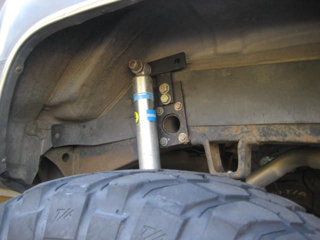
For the shock mounts, I kept using the upper wheel well, bolt on towers from before. For the lower mounts, I modified the lower spring plates again! I forgot to take a before picture, but previously in this build thread I probably showed them? Anyway, I modified the spring plates this time to allow them to sit almost 2" lower and make it easier to install the shock. Before I had to compress the shock while off the vehicle and then strap it to hold compression. Then I would attach the upper end then release the strap to let it unload into the lower shock mount. The new design allows me to attach to the upper shock mount and then push / compress the shock from below up into the lower mount. Just a little easier.
 Jan 5, 2013 | 08:22 PM
#204
Thread Starter
Registered User
Joined: Jun 2009
Posts: 977
Likes: 4
From: Southern California
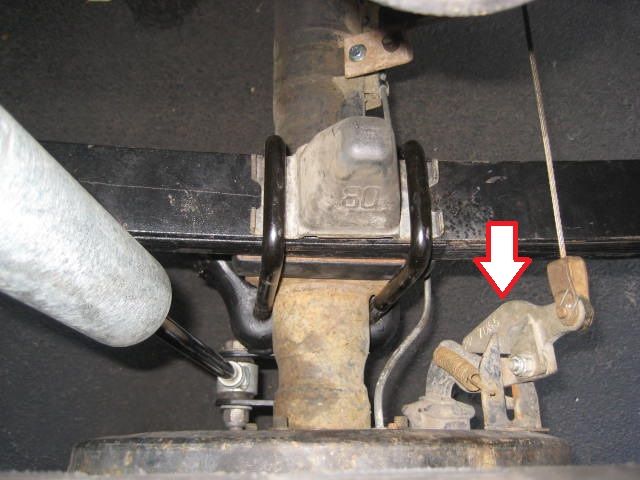
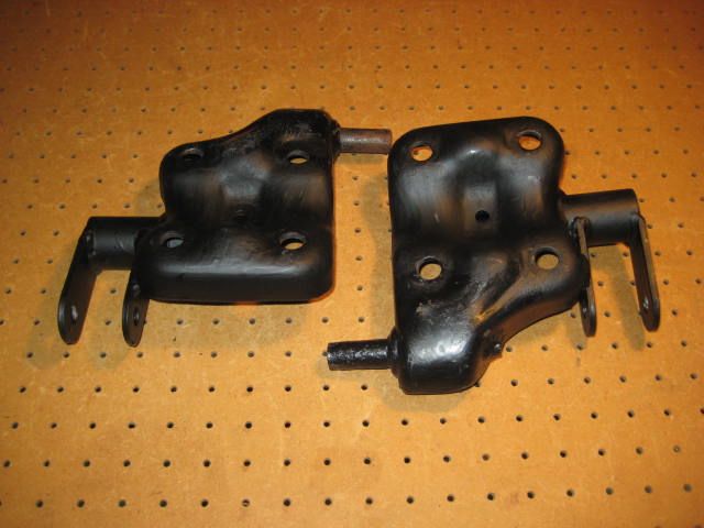
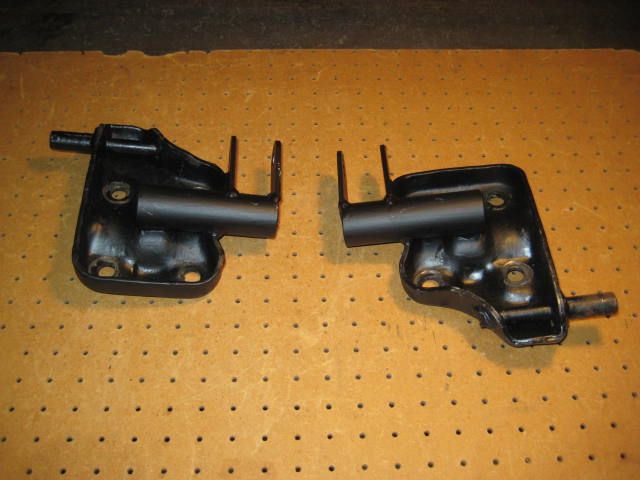
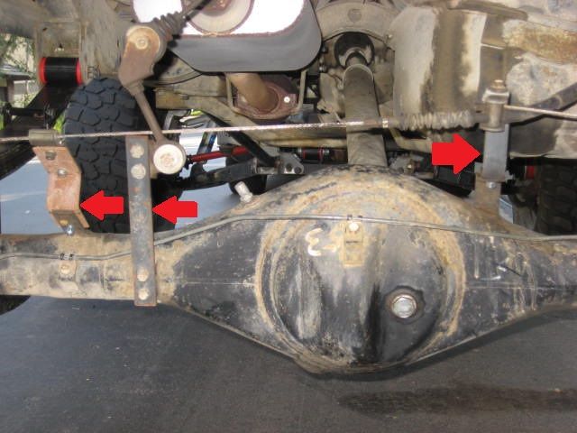
I had make to make an extension bracket to get the brake equalizer to work properly. Arrow in the middle. Its made from 1"x 3/16" flat stock. For the parking break I also made some extension brackets where it attaches to the axle housing. The one on the right is made from 1"x 3/16" flat stock and the one on the left is 1-1/2" x 1/8" flat stock.
The parking brake cable is obstructed by the 1.5" block and leaf spring pack to attach to the drum assembly. The Block kit included this extension bracket (red arrow on the second photo) that raises the cable above the leaf pack. I believe the 1.5" Block Kit is a Superlift product.
The parking brake cable is obstructed by the 1.5" block and leaf spring pack to attach to the drum assembly. The Block kit included this extension bracket (red arrow on the second photo) that raises the cable above the leaf pack. I believe the 1.5" Block Kit is a Superlift product.
Jan 5, 2013 | 08:25 PM
#205
Thread Starter
Registered User
Joined: Jun 2009
Posts: 977
Likes: 4
From: Southern California
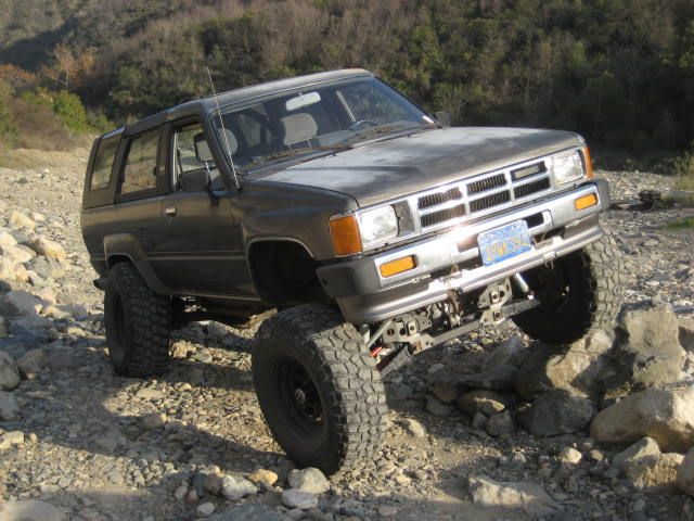
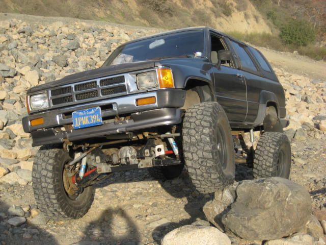
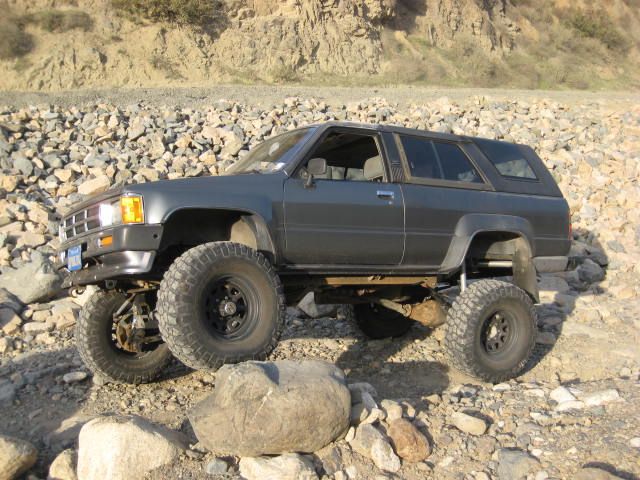
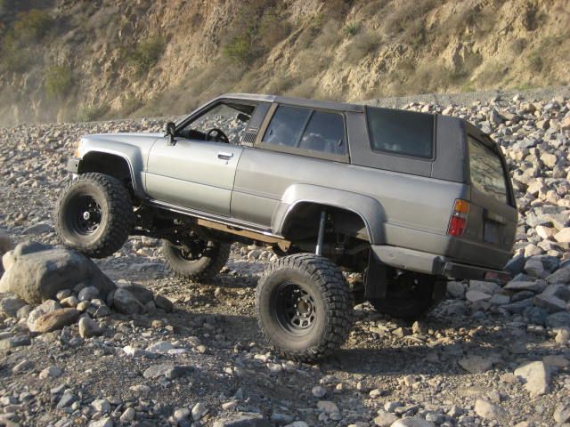
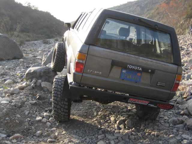
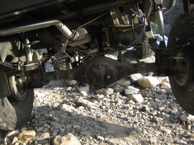
This afternoon I took the Runner out to the canyon and found a couple of boulders to flex out the suspension on. I didn't have much time and the off road access has recently been limited so I didn't get a real feel for the performance aspects. It was good I got to twist up the suspension as I did find some areas needing attention. Here is a series of photos I took as I walked around the rig.
Jan 5, 2013 | 08:27 PM
#206
Thread Starter
Registered User
Joined: Jun 2009
Posts: 977
Likes: 4
From: Southern California
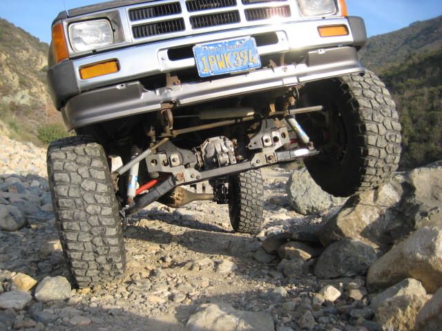
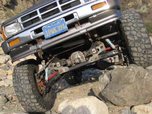
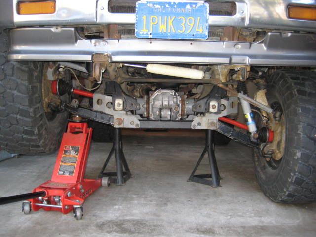
Here are some close up photos. The Center Mount Differential and lengthened CVs are no where near the operating limits. The BJs and Tie Rods also have plenty of room to grow. I observed the factory droop stops were limiting droop but the bump stops didn't hit the LCAs. I believe the shocks are limiting the up travel. I'll have to check the measurements another day.
I am planning on putting the shock hoops back on and running a coil over conversion eventually so that solves the shock issues. I suspect I can get a bit more droop with low profile droop stops or by removing them all together and putting an adjustable limit strap in the old shock location. For up travel I need to remove the factory bumps and revisiting the metal to metal measurement. The Pro Comp Stage II bracket kit integrates the bump stops with the pivot drop bracket so its not as easy to modify as some of the other drop bracket kits. I'll probably have to take the assembly off the truck to perform surgery. It will be interesting to see how much more travel I can get with minor modifications.
I am planning on putting the shock hoops back on and running a coil over conversion eventually so that solves the shock issues. I suspect I can get a bit more droop with low profile droop stops or by removing them all together and putting an adjustable limit strap in the old shock location. For up travel I need to remove the factory bumps and revisiting the metal to metal measurement. The Pro Comp Stage II bracket kit integrates the bump stops with the pivot drop bracket so its not as easy to modify as some of the other drop bracket kits. I'll probably have to take the assembly off the truck to perform surgery. It will be interesting to see how much more travel I can get with minor modifications.
Last edited by BlazeN8; Jan 5, 2013 at 08:29 PM.
Jan 5, 2013 | 08:36 PM
#207
Thread Starter
Registered User
Joined: Jun 2009
Posts: 977
Likes: 4
From: Southern California
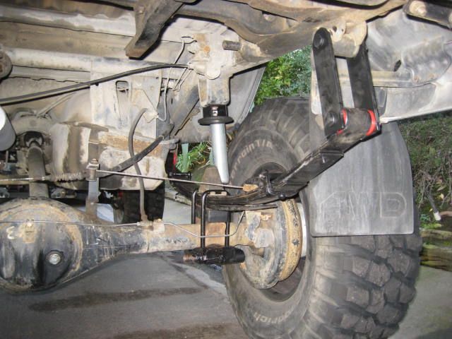
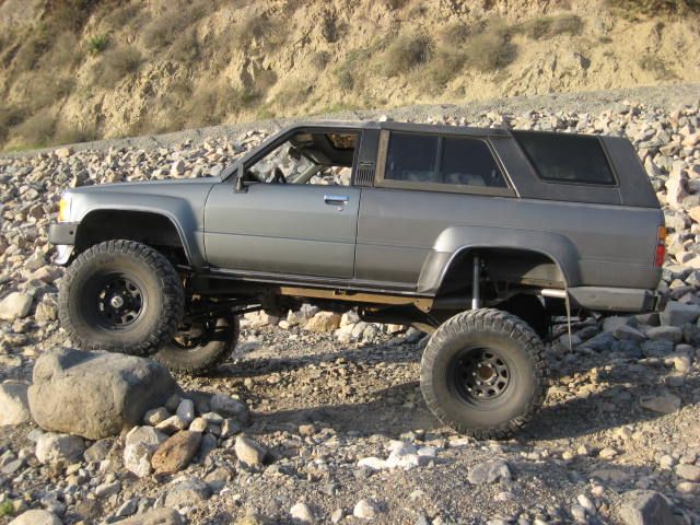
The rear suspension seems to be flexing fairly well. In the photo posted below you can see the passenger side tire is off the ground and that side is dropped a good distance. There is quite a bit extension remaining in the shock. I stood on the wheel and with my weight it drooped a bit more. The driver side shock had lots of compression stroke remaining as well. The bump stop is a couple of inches from contacting the shim plate and the tire is a couple of inches from hitting the fender. I think a dynamic impact will result in bump stop contact, but for now I think it will do.
Last edited by BlazeN8; Jan 5, 2013 at 08:38 PM.
Jan 6, 2013 | 01:35 PM
#209
Thread Starter
Registered User
Joined: Jun 2009
Posts: 977
Likes: 4
From: Southern California
Yeah, I know the front will handle way more up travel. I tested it a while back on the frame section I use for mock up without bump stops and it would go another 1.5" before metal on metal. I believe if I were to modify the pivot brackets I could find even more. I almost went with low pro bumps when I first installed the combo kit but the low pro bumps I had were turning to chalk they were so old. Also, at that time I didn't have the correct shocks to maximize the travel so I just used the factory bumps.
Even without the center mount differential (CMdiff) and custom CVs (CCVs), the combo kit will handle more up travel. If you look at some of the other guys build threads, they're not even using the bump stop spacer brackets or bump stops! In their photos the angle of the CV at stuff is past horizontal where mine isn't. With the CMdiff and CCVs there is tons of room for up travel as well as down. Will the BJs and Tie Rod Ends handle it? We shall see!
BTW- I'm not all that excited about pulling off the Pro Comp pivot brackets for modification, but think its got to be done. I'll check the metal to metal this week and see where that's at. Stay tuned.
Jan 6, 2013 | 02:40 PM
#210
Thread Starter
Registered User
Joined: Jun 2009
Posts: 977
Likes: 4
From: Southern California
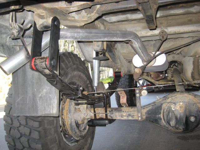
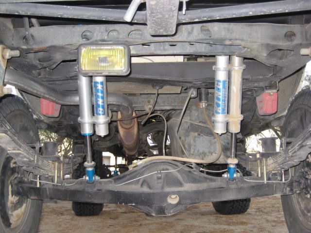
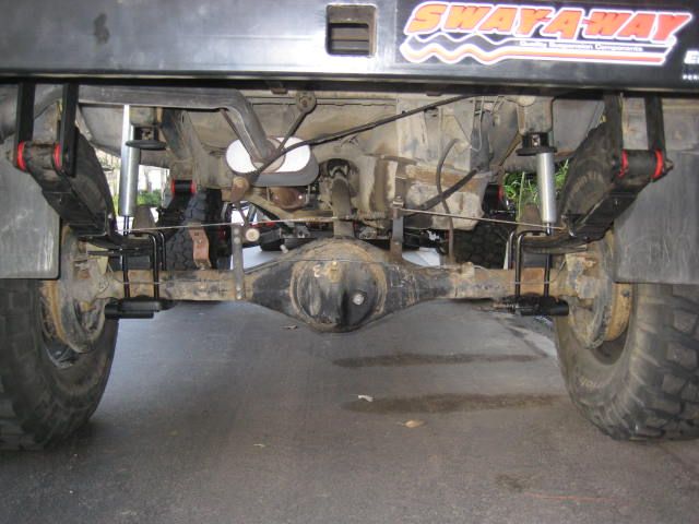
With this rear suspension upgrade in mind I looked back at some photos of my friend James 1992 SAS 4Runner. He installed a 6" lift All-Pro L.T. rear leaf pack with 12" travel remote res. 2.5 shocks. This is sort of the direction I was wanting to go but not so sure anymore. I don't think his set up is showing anymore up travel evident by comparing the bump stops and the down travel cant be much more as his shocks are only 12" of travel and he said he was using every inch of stroke. Compare these two photos!
Last edited by BlazeN8; Jan 6, 2013 at 03:21 PM.
Jan 8, 2013 | 12:39 PM
#211


looks great! always good to see your LT getting tweaked further. this version seems legit if you address the bump stops issue.
as for the rear shocks, both setups look like they'd perform the same to me - but he might have slightly more travel because they're closer together than your setup. why not just use triangulated shocks if they fit in that orientation? seems like the setup to go with if you want max down-travel. i dunno if it'll work with your setup, but for me it gave me a couple inches more travel with the same setup, just changed how the shocks mounted.
as for the rear shocks, both setups look like they'd perform the same to me - but he might have slightly more travel because they're closer together than your setup. why not just use triangulated shocks if they fit in that orientation? seems like the setup to go with if you want max down-travel. i dunno if it'll work with your setup, but for me it gave me a couple inches more travel with the same setup, just changed how the shocks mounted.
Jan 8, 2013 | 08:39 PM
#212
Thread Starter
Registered User
Joined: Jun 2009
Posts: 977
Likes: 4
From: Southern California
highonpottery, (great handle by the way)
I think you got confused between my front and rear suspension dialog, my rear shocks are fine, its the front shocks that are causing problems.
To recap the rear suspension comparison photos- the photo showing the 2.5 diameter 12" travel King Shocks located behind the axle and angled back is using nearly every inch of the shock stroke. This is Jame's 1992 4 Runner. The photo showing the 2.0 diameter 14" travel Bilsteins is not using all available shock stroke. This is my rig. Nothing is limiting the travel except the leaf spring its self. There are a couple of reasons why I positioned my shocks forward and outside the frame rail. First is because I don't have a 3" body lift like Jame's does. Secondly, I wanted to use a longer shock than he is because I knew he was maxed out. Thirdly, I didn't want to penetrate into the passenger cabin. By going outside the frame rails and up into the wheel well I accomplish all these goals.
But there are some more factors! When shocks are mounted in an a-frame like you mentioned, with an angle pointing inward and back, you decrease the efficiency. It is best to locate a shock as far out on the axle as possible and with the least amount of angle (both in/out or back/forward) as possible. The shock should point "in line" with the travel movement of the axle. This is the most effecient use of the shock, but it also requires the most stroke of the shock.
The front suspension of on a IFS rig followes the over-all concept as the rear but there are some differences. Think of the LCA as the leaver arm, the frame bushings as the pivot, and the ball joint as the applied force. The shock represents the fulcrum point. The most efficient shock placement location would nearest to the ball joint where the force is matched 1 to 1. The closer the shock moves towards the pivot the ration changes and its harder for the shock to counter the force. As this happens the valve settings needs to be adjusted. Shock angle is another factor in the geometry. If your angle is in line with the force direction that is the most efficient. When the shock is angled over it looses efficiency but as the angle increase it requires less stroke.
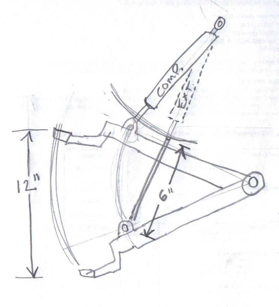
I get a lot of people writing me with questions about how I am getting 12" of wheel travel and only using a 8" travel shock. Wheel travel and shock travel are not the same. Here is a sketch that might explain it better than my written description.
I think you got confused between my front and rear suspension dialog, my rear shocks are fine, its the front shocks that are causing problems.
To recap the rear suspension comparison photos- the photo showing the 2.5 diameter 12" travel King Shocks located behind the axle and angled back is using nearly every inch of the shock stroke. This is Jame's 1992 4 Runner. The photo showing the 2.0 diameter 14" travel Bilsteins is not using all available shock stroke. This is my rig. Nothing is limiting the travel except the leaf spring its self. There are a couple of reasons why I positioned my shocks forward and outside the frame rail. First is because I don't have a 3" body lift like Jame's does. Secondly, I wanted to use a longer shock than he is because I knew he was maxed out. Thirdly, I didn't want to penetrate into the passenger cabin. By going outside the frame rails and up into the wheel well I accomplish all these goals.
But there are some more factors! When shocks are mounted in an a-frame like you mentioned, with an angle pointing inward and back, you decrease the efficiency. It is best to locate a shock as far out on the axle as possible and with the least amount of angle (both in/out or back/forward) as possible. The shock should point "in line" with the travel movement of the axle. This is the most effecient use of the shock, but it also requires the most stroke of the shock.
The front suspension of on a IFS rig followes the over-all concept as the rear but there are some differences. Think of the LCA as the leaver arm, the frame bushings as the pivot, and the ball joint as the applied force. The shock represents the fulcrum point. The most efficient shock placement location would nearest to the ball joint where the force is matched 1 to 1. The closer the shock moves towards the pivot the ration changes and its harder for the shock to counter the force. As this happens the valve settings needs to be adjusted. Shock angle is another factor in the geometry. If your angle is in line with the force direction that is the most efficient. When the shock is angled over it looses efficiency but as the angle increase it requires less stroke.
I get a lot of people writing me with questions about how I am getting 12" of wheel travel and only using a 8" travel shock. Wheel travel and shock travel are not the same. Here is a sketch that might explain it better than my written description.
Last edited by BlazeN8; Jan 8, 2013 at 08:54 PM.
Jan 8, 2013 | 09:01 PM
#213
Thread Starter
Registered User
Joined: Jun 2009
Posts: 977
Likes: 4
From: Southern California
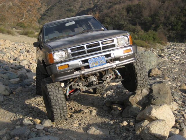
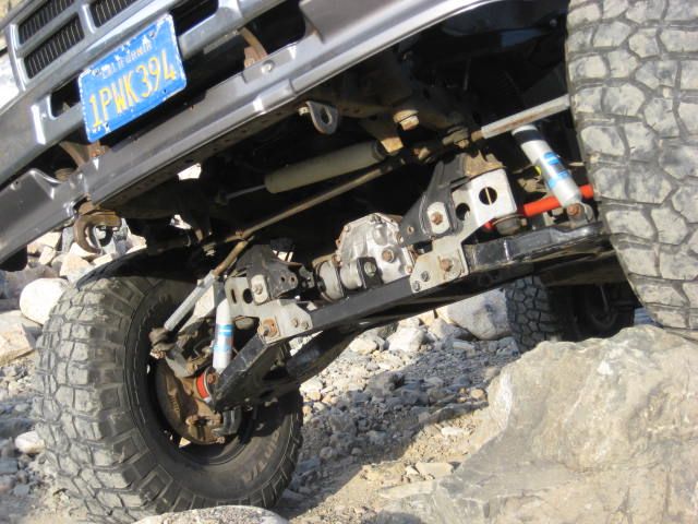
Driving my rig up the make shift RTI bolder stack uncovered a problem, something is obviously limiting the up travel?
This morning back at home in the garage, I put the vehicle on jack stands drooped out the suspension. I removed the pre-load to the passenger side torsion bar allowing the suspension to be jacked up without any spring load. Then it was just a matter of cycling the suspension up and down making observations and taking measurements.
Measurements on wheel travel, taken at the center line of the hub, revealed metal to metal to be 10.75" This means the 4" drop bracket kit reduces over all wheel travel from the stand alone Blazeland Long Arms, by about 1"
The Combo kit equipped 4 Runner at ride height is about 6" higher than stock, and 2-3" higher than the stand alone Blazeland Long Arms. From ride height I measured 4-1/2" of down travel and 6-1/4" of up travel.
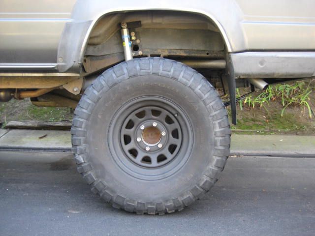
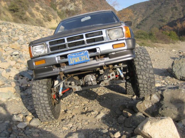
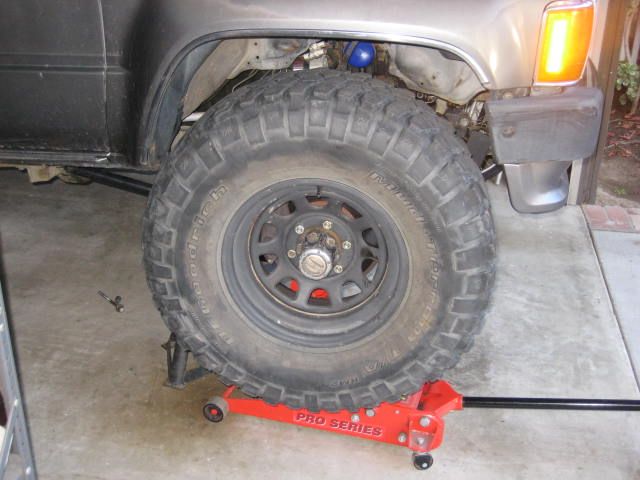
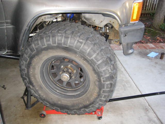
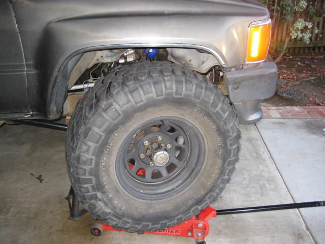
With the suspension compressed without bump stops there is about 3-1/2" of clearance between the tire and the fender. Tires are 315x75R15 BFG M/T's which is basically a 35" tall tire. As you can see in the photos when the steering is turned right or left there is some rubbing. With minimal bump stops back in place this contact is eliminated.
This morning back at home in the garage, I put the vehicle on jack stands drooped out the suspension. I removed the pre-load to the passenger side torsion bar allowing the suspension to be jacked up without any spring load. Then it was just a matter of cycling the suspension up and down making observations and taking measurements.
Measurements on wheel travel, taken at the center line of the hub, revealed metal to metal to be 10.75" This means the 4" drop bracket kit reduces over all wheel travel from the stand alone Blazeland Long Arms, by about 1"
The Combo kit equipped 4 Runner at ride height is about 6" higher than stock, and 2-3" higher than the stand alone Blazeland Long Arms. From ride height I measured 4-1/2" of down travel and 6-1/4" of up travel.
With the suspension compressed without bump stops there is about 3-1/2" of clearance between the tire and the fender. Tires are 315x75R15 BFG M/T's which is basically a 35" tall tire. As you can see in the photos when the steering is turned right or left there is some rubbing. With minimal bump stops back in place this contact is eliminated.
Jan 8, 2013 | 09:14 PM
#214
Thread Starter
Registered User
Joined: Jun 2009
Posts: 977
Likes: 4
From: Southern California
So what was limiting travel on the RTI bolder? Well, I had looked at the droop stop on the side that was hanging and it was compressed, but maybe not all the way? I looked and bump stops on the side that was stuffed and the bump stops were not touching? You can see this in the photos from earlier. My first guess was it was a shock that was bottoming out.
The shock I am using is Bilstein 5100 for a 4" lift. The part number is 24-185745. This is a bolt in configuration using stock mounting points. The valve setting is specific to this vehicle. The extended length is 17.95, the compressed length is 11.67, the travel / stroke is 6.28
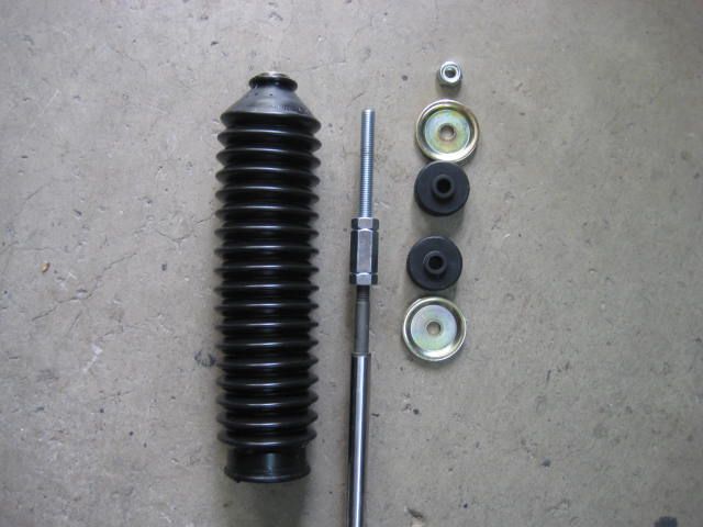
But, since I have long arms and a bracket kit, 4" lift is not nearly enough! To add some length I took a metric rod coupler and some jam nuts and made an extension. This didn't change the travel / stroke but made it 4-1/2" longer. Now the extended length is 22.50 and the compressed length is 16.50 And with the boot in place no one ever has to know.
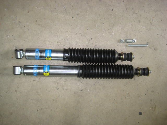
The shock I am using is Bilstein 5100 for a 4" lift. The part number is 24-185745. This is a bolt in configuration using stock mounting points. The valve setting is specific to this vehicle. The extended length is 17.95, the compressed length is 11.67, the travel / stroke is 6.28
But, since I have long arms and a bracket kit, 4" lift is not nearly enough! To add some length I took a metric rod coupler and some jam nuts and made an extension. This didn't change the travel / stroke but made it 4-1/2" longer. Now the extended length is 22.50 and the compressed length is 16.50 And with the boot in place no one ever has to know.
Jan 8, 2013 | 09:16 PM
#215
Thread Starter
Registered User
Joined: Jun 2009
Posts: 977
Likes: 4
From: Southern California
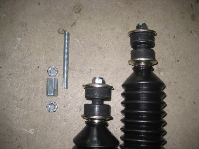
The shock mounting distances with bumps are as following: ext 22.75, comp 18.25 As you can see from the numbers the shock works if I add 1/4" shim to the extension. With out bumps: things change, ext 23.25, comp 15.50 From these revised numbers the shock still works extended if I add 1/2" shim. So I added a 1/2" shim just above the coupler and jam nut.
I will be using bumps stops of some type? Not because the collapsed length bottoms out on its self by 1" but because smacking metal LCA to metal bracket would mess stuff up real quick.
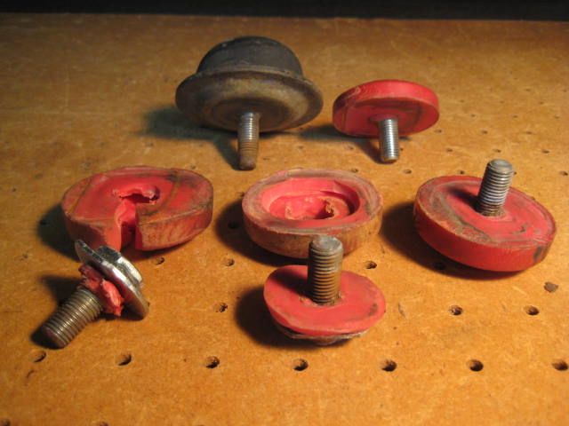
The thick rubber factory bumps have lots of cushion and are really strong with the bonded rubber to a metal backing plate. I was wanting to put some low profile poly bumps in there and just make sure I didn't hammer through the whoops or jump. I have a box of various bumps and found a miss matched set of (4) but as I bolted it the second one it stripped out something inside the poly. Are you kidding me, this stuff is junk, back to the pack rat box of bumps. Now I am asking myself do I just buy a set of low pro poly or do I take off the pivot bracket and modify it to use factory bumps just recessed up an inch. Sounds like a lot of work. Oh, what to do?
I will be using bumps stops of some type? Not because the collapsed length bottoms out on its self by 1" but because smacking metal LCA to metal bracket would mess stuff up real quick.
The thick rubber factory bumps have lots of cushion and are really strong with the bonded rubber to a metal backing plate. I was wanting to put some low profile poly bumps in there and just make sure I didn't hammer through the whoops or jump. I have a box of various bumps and found a miss matched set of (4) but as I bolted it the second one it stripped out something inside the poly. Are you kidding me, this stuff is junk, back to the pack rat box of bumps. Now I am asking myself do I just buy a set of low pro poly or do I take off the pivot bracket and modify it to use factory bumps just recessed up an inch. Sounds like a lot of work. Oh, what to do?
Last edited by BlazeN8; Jan 9, 2013 at 02:41 PM.
Jan 8, 2013 | 09:28 PM
#216
Thread Starter
Registered User
Joined: Jun 2009
Posts: 977
Likes: 4
From: Southern California
So I never really answered the question of what is limiting up travel did I. I know the shocks would limit up travel before the metal on metal....... but that's not the case here, I wasn't even into the bumps? Nothing in the ball joints, tie rod ends, or CV is showing signs of binding on the jack stands! Maybe it was just the way this particular obstacle flexed things?
I am suspicious its a T-Bar 26 mm spring rate thing. 26mm works great in the desert and dunes but it might be too stiff for crawling? The stock 22mm T-bars don't hold the lift and it sags even at max pre-load. I know Toyotech and a few others have been using the 22mm T-bars for crawling with success! It sits lower but it will flex better with up travel.
I just don't have it figured out right now, but give me time, I'll get it squared away!
Last edited by BlazeN8; Jan 8, 2013 at 10:07 PM.
Jan 9, 2013 | 02:29 PM
#217

Registered User
Joined: Nov 2006
Posts: 580
Likes: 33
From: Saginaw, MN
Love it! Not going to lie, I spent some time staring at the front of my truck this weekend when I swapped wheels trying to picture the feasibility of doing the center-mount diff without the bracket lift. ugh. Might not happen.
Also, after you last post, I'm glad I haven't bought beefier torsion bars, yet. Although I may want them anyway, I'll be rock crawling, but I also have a muuuuch heavier motor (4.3) in there. We'll see. REALLY hope to get one of your kits this summer.
Also, after you last post, I'm glad I haven't bought beefier torsion bars, yet. Although I may want them anyway, I'll be rock crawling, but I also have a muuuuch heavier motor (4.3) in there. We'll see. REALLY hope to get one of your kits this summer.
Jan 9, 2013 | 02:58 PM
#218
Thread Starter
Registered User
Joined: Jun 2009
Posts: 977
Likes: 4
From: Southern California
I think a big reason why the front isn't flexing has to do with weight distribution. When the front is higher than the rear the weight unloads off the front and transfers to the rear. If the vehicle is level or pointing down hill it will compress the suspension better. I suspect lighter spring rate torsion bars are not going to change this. Neither will a coil over conversion.
What it needs is a computerized dynamic leveling system. Add additional spring rate to the rear passenger corner and reduce it at the driver front.
Maybe in some situations the IFS rigs may benefit from a rear sway bar. Something that isn't very strong, but just enough counter force to match the front tendency to level out?
Last edited by BlazeN8; Jan 9, 2013 at 03:06 PM.
Jan 9, 2013 | 04:10 PM
#219
Registered User
Joined: Jan 2005
Posts: 131
Likes: 0
From: T90
It will be interesting to see how long those extension rods hold up.
At least tell us that you went grade 8 on them?
And that you didn't over-crush the bushings. They should be tight enough so the bushing just barely starts to deform; many people over tighten them.
At least tell us that you went grade 8 on them?
And that you didn't over-crush the bushings. They should be tight enough so the bushing just barely starts to deform; many people over tighten them.
Jan 9, 2013 | 05:08 PM
#220
Thread Starter
Registered User
Joined: Jun 2009
Posts: 977
Likes: 4
From: Southern California
Hey Tim,
The shock extension rod, coupler, and jam nuts were some off the shelf items at a local hardware store. I didn't even investigate the grade of these items. I was just happy to find something so I would at least have a shock. It was never intended to be more than a quick fix. I installed this in April of 2011! Anyway what's the worst that could happen, I bend the rod, big deal. Its not like the wheel would fall off and I would crash and burn!
When I put the combo kit on the Runner I all ready had these shocks. I looked around for some bolt on shocks that were long enough but couldn't find anything. The 18mm metric bolt and wide tab width at the LCA and the bayonet style at the upper tab are unique and nothing matches up.
Funny story, I called Bilstein and tried to see if I could get some special order shocks built to my specifications. That didn't go over well, I was pretty much laughed at for asking stupid questions. Seems to me it would be fairly easy to take the existing design and put that into a longer shock body and use a longer rod. It would work great and the combo kit enthusiast would have the correct length shock. It would bolt right in, have the correct valve settings, and show 8" travel in stroke. The perfect inexpensive solution and not my Mickey Mouse rod coupled BS.
Yeah, I didn't over tighten the hardware and crush the bushings. Somewhere on a YT thread I noticed one of my customers had and I wrote a post with that same advice. You read that and are mocking me aren't you? Too funny!
I got the latest issue of 4WD T.O. magazine today. Full page add on P.11 for another LT kit builder. I checked out the website. I didn't see 86-95 4x4 but he had some nice parts. The clearance'd / modified inner CV barrels looks like something I need to get for the Fordota since I am not going CMdiff on that rig.
Last edited by BlazeN8; Jan 9, 2013 at 05:14 PM.


