
Wiring Question
 Feb 22, 2010 | 07:24 PM
#21
Registered User

Joined: Jan 2009
Posts: 1,908
Likes: 5
From: Fresno, Ca.
Maybe my advice is more confusing than anything because I was dealing with a 97 auto. I dont want to screw you up.
I would just say match the wires up.
You should really only need the EFI power, battery power, output to COR (fuel pump relay), oil pressure, water temp, tach, speedo return wire, OBD2, and a few more that I cant think of. Run your wires from the VSS and match them in your kick panel as per my write up in my thread.
Are you in California?
Feb 22, 2010 | 07:26 PM
#22
Registered User
Joined: Jan 2009
Posts: 1,908
Likes: 5
From: Fresno, Ca.
Feb 22, 2010 | 07:41 PM
#23
Thread Starter
Registered User
iTrader: (1)
Joined: Jan 2010
Posts: 198
Likes: 2
From: St.George, UT
Ya i see what you are saying . I will just keeping studying these diagrams with acrobat. No California for me I wish. I live about 5 hours away in St.George Utah. Thanks again for all you help.
Feb 22, 2010 | 08:01 PM
#24
Registered User
Joined: Jan 2009
Posts: 1,908
Likes: 5
From: Fresno, Ca.
california is nice in 1000's of ways other than taxes, environmental nonsense, and 3.4 swaps!!
You are best to really study those things. I was overwhelmed at once. If you saw my thread and that massive monster of wire you can see I mean. Mu suggestion is to take it ONE wire at a time. Understand what it does, why its there and can the motor run without it(abs, etc.). then move to the next wire. It took me a good week every night going through every one till i had it where I thought I understood. Then when I was ready to start splicing together I felt like I was confused again so took the night off.
Came back and went for it and everything was pretty clear then.
Feb 22, 2010 | 08:19 PM
#25
Contributing Member
Joined: Apr 2008
Posts: 654
Likes: 1
From: Colorado Springs, Colorado
To answer your question the plugs mostly go to the same things though some will have a rouge wire crossing through the plug. To your computer will be E5 and E6, Your body plugs should be IK2 and IK6 which mate to IH1 and IH2. It's a fun process. 
Feb 22, 2010 | 08:29 PM
#26
Thread Starter
Registered User
iTrader: (1)
Joined: Jan 2010
Posts: 198
Likes: 2
From: St.George, UT
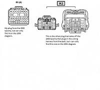
Okay so here is where i am at. Maybe someone can help. So i have identified all of my plugs. The problem i am having is the two plugs off of the 2000 tacoma dash. I can find both plugs on TIS but not on the 2000 diagram. I find one on the 1999 and the other on the 2001, is this going to be a problem? I am so confused. Here is a pic of the plugs. The main question is can i just find and label the wires normal even though they are on different year diagrams, will it still work out?
 Feb 22, 2010 | 08:41 PM
#27
Registered User
Joined: Jan 2009
Posts: 1,908
Likes: 5
From: Fresno, Ca.
I had similar issues with diagrams not matching what I had. I ended up using a 95 runner diagram for my 92 pickup and everything worked fine.
All my 97 stuff was correct on the diagrams though except for a few things that i cant remember that I had to use a 99 diagram for.
I would check that the 99 and 01 diagrams have the same wire colors for specific functions. For example, is the EFI power white/blue (W/L) in both? If so, its safe to say that your 2000 is also i would think. Then go to the next wire and so on.
I doubt that they changed colors from 99 ->2000 and then back in 2001.
Is this clear or nonsense ??
Feb 22, 2010 | 08:51 PM
#28
Thread Starter
Registered User
iTrader: (1)
Joined: Jan 2010
Posts: 198
Likes: 2
From: St.George, UT
I understand exactly what you are saying and that is kind of what i was thinking. So from the picture i posted it is safe to say that plugs are IK2 and E5. So i am clear one more time those are really the only two plugs i have to splice and adapt to the 3.0 stuff (and a very odds and ends of course) and then the other plugs on the harness go into the computer then i am good. Right? of am i still off a bit? Thanks again dntsdad.
Feb 22, 2010 | 09:06 PM
#29
Registered User
Joined: Jan 2009
Posts: 1,908
Likes: 5
From: Fresno, Ca.
To be really honest, I never quite grasped the IK2 and whatever labelling system. All the diagrams I had labeled plugs differently so I quit using those to look for anything other than punching them into Acrobat's search.
What I would do i find a wire color in that plug, say W-L (EFI power).
Search W-L in Acrobat.
Let Acrobat find the wire in the diagram and then find the junction (plug).
Copy that plug number IK2, C1, whatever. Highlight that in Acrobat, copy, paste into the search box, and then go through the whole document. Then I have Acrobat doing the work of finding every wire in that plug for me. I just labeled them after it did the hard part.
Worked perfectly.
Did you disassemble everything yourself? If so, the plugs that ran from the motor should have went straight into the ECM. Those you shouldnt have to mess with.
The one that came out and joined to your body harness is the one you will be splicing. Again though, I didnt really pay attention to their labels(names) just colors.
Sorry I cant be more helpful. Hopefully someone else can.
Last edited by dntsdad; Feb 22, 2010 at 09:08 PM.
Feb 22, 2010 | 09:38 PM
#30
Thread Starter
Registered User
iTrader: (1)
Joined: Jan 2010
Posts: 198
Likes: 2
From: St.George, UT
I will do that with Adobe. That is a really good idea. Ya i took it apart so i know what plugs you are talking about. Well i will continue to plug on. I will update my progress.
Maybe you will know this do i have to have these two plugs wired up to start the motor? or can i just hook up the motor ones? and the starter relay? fuse box power?
Maybe you will know this do i have to have these two plugs wired up to start the motor? or can i just hook up the motor ones? and the starter relay? fuse box power?
Feb 23, 2010 | 04:39 AM
#33
Contributing Member
Joined: Apr 2008
Posts: 654
Likes: 1
From: Colorado Springs, Colorado
Yeah those are E5 and IK2. What I did was go through and find every wire that goes into each connector. You will notice a little number next to the plug, that is the position of the wire in the connector. If that matches your all good. On occasion I found they did not match. So like DNTSDAD said you may want to cross check to other years or other models.
Feb 24, 2010 | 04:12 AM
#34

Registered User
Joined: Feb 2010
Posts: 10
Likes: 0
From: Canon City, Colorado
When I did my swap i started to make a list of all the wires that went to the correct plugs but when the time came to wire it I couldnt read my own handwriting and my stupid description of what the wire was for. It made since when I wrote it. I ended up just laying the diagrams next to each other and splicing one wire at a time. I think I only needed 5 or 6 wires for it to start up, but I'm very inpatient (there is no way I could work on this project for a year like most, I did mine in two weeks including engine build time. three weeks if you count me adding a supercharger a week later). I also did all the wiring with the engine and harness in truck, some of the wires were different colors on each side of the plug.
Feb 24, 2010 | 06:41 PM
#35
Thread Starter
Registered User
iTrader: (1)
Joined: Jan 2010
Posts: 198
Likes: 2
From: St.George, UT
So this may be a long shot but here is a list of my plugs with the wires, and i was wondering if anyone can fill in some blanks or correct me on what i have found so far. I know with different years they might be different but i guess it does not hurt to ask ... Thanks everybody.
1991 4runner
IH1
1.W-B
2.G-W
3.V Check engine
4.X
5.G-W Stop Light SW
6.L Check Connector
7.X
8.B-R
9.Y-B
10.B-G EFI
11.X
12.W-G
13.X
14.B-R IG2 Ignition SW
15.X
16.W-R to A/C Idle up VSV
17.X
18.X
19.X
20.G-L Speed Sensor
21.X
22.B-W Starter Relay
23.G-Y Circuit Open Relay COR
24.X
IH2
1.X
2.G-W
3.X
4.X
5.L
6.B-R
7.R-W
8.B-BR
9.X
10.G-Y
11.Y-G
12.X
13.X
14.Y-G
15.B-W
16.X
17.X
18.X
19.X
20.B
Feb 24, 2010 | 06:45 PM
#36
Thread Starter
Registered User
iTrader: (1)
Joined: Jan 2010
Posts: 198
Likes: 2
From: St.George, UT
2000 Tacoma
IK2
1.B-R
2.R-B
3.G-B
4.W-B
5.X
6.G-R
7.R-W
8.Y-L
9.BR
10.Y-R
11.B
12.X
13.W-R
14.B-Y
15.B-O
16.B-O
17.X
18.Y-B
19.P-B
20.L
21.B-W
22.V-P
23.BR
24.B-R
25.G-Y
26.GR
E5
1.X
2.X
3.X
4.X
5.L-B
6.X
7.X
8.X
9.X
10.X
11.G-R
12.G-O
13.X
14.B-Y
15.X
16.L-Y
17.X
18.X
19.X
20.X
21.X
22.X
23.W-R
24.G-W
25.X
26.X
27.X
28.X
Feb 25, 2010 | 10:37 PM
#38

Registered User
Joined: Nov 2009
Posts: 150
Likes: 0
From: Portland Or.
Your plugs are different than mine, but i did notice you only listed one wire for the speed sensor. All i know is mine was a three wire, i used the stock 92 sensor. The three speed sensor wires were on the same plug for me. Also i didn't notice your tach, oil pressure, engine temp, or transfer case postion switch(so your 4wd lamp lights up on the dash) listed.
Sorry i cant be more help.
Sorry i cant be more help.
Feb 26, 2010 | 07:05 AM
#39
Contributing Member
Joined: Apr 2008
Posts: 654
Likes: 1
From: Colorado Springs, Colorado
Here is what I copuied out of my thread. Hope it helps
https://www.yotatech.com/forums/f160...13/index6.html
E5- Connector
1. L-V =Batt to IH1 B-G =Constant power to ECU
2. B-L =IGSW to IK2 B-R =IGSW
3. G-Y =FC to G-Y =Circuit Open Relay To Air Flow
4. X
5. X
6.V =W to IH1 V =Check Engine Light
7. B-W =STA to Stater
8. GR-B =MREL to IH1 B-R =Power To Ignition Coil
9. Y-G =TPC to IK6
10. X
11. W =SIL to OBD2 W =SIL
12. X
13. X
14. X
15. G-W =STP to IH1 G-W =Stop Light Switch to ECU
16. W-L =+B to IH1 W-R = Switched Power
17. Y =PTNK to IK6
18. X
19. X
20. X
21. X
22. X
E6
1. X
2. R-Y =R to IK2 R-B =Park Neutral Switch (Reverse)
3. V-R =2 (2nd Gear?) to
4. Y-G =IDLO to IK2 BR =Data Link Connector to Ground and IH1 Y-B = From Cruise Control ECU to Check Conector
5. X
6. L-W =ODMS to Nothing (ADD)
7. Y =OILW to Nothing (ADD)
8. R =OXS to IK2 BR =OXS
9. R-W =HTS to IK2 BR
10. L-O =ODLP to Nothing (ADD)
11. X
12. LG =L (Low Gear?) to
13. L-B =ACT to IH2 B-R A/C Amplifier To Engine ECU
14. X
15. X
16. X
17. R-G =TFN to IK2 W-B = Neutral Position Switch
18. L =4wd Detection Switch
19. L-R =Low 4 Detection Switch to IK2 GR =Low 4 Detection Switch
20. B =
21. X
22. G-O =SP1 to IK2 =G-B =speedometer
23. X
24. BR-Y =OD1 to IH1 Y-B From Cruise Control ECU to Check Connector
25. L-Y =AC1 to IH1 L-B =A/C Amplifier To ECU and Transmission
26. X
27. X
28. X
IH1
1. W-B- GND for the transfer case
2. X
3. V - To Check Engine Light
4. X
5. G-W- Stop LightSW to ECU
6. L - FP In check Connector
7. L-B - a/c amplifier to ECU and transmission
8. B-R - Anti Lock to Check Connector
9. Y-B - From cruise control ECU to check connector
10. B-G - Constant power for ECU
11. X
12. W-G - Ground for ECU
13. X
14. B-R -Power to ignition coil
15. X
16. W-R - Switched Power
17. X
18. X
19. X
20. G-L- Speed sensor
21. X
22. B-W- Starter to starter relay
23. G-Y - Circuit open relay to air flow
24. X
IH2
1. X
2. G-W - Transfer Oil pressure Sw
3. X
4. X
5. L - a/c amplifier to engine ECU
6. B-R - a/c amplifier to engine ECU
7. R-W - trans. R-W
8. B-BR - trans. B-BR
9. X
10. G-Y - ADD indicator SW to 4 wd light
11. Y-L - Oil pressure sender
12. X
13. G-L - Vehicle speed sensor
14. Y-G - Water temp.
15. B-W - a/c amplifier to engine ECU
16. X
17. X
18. X
19. G-R - trans G-R
20. B - ignitor to a/c amplifier
Feb 26, 2010 | 04:00 PM
#40
Registered User
Joined: Feb 2007
Posts: 40
Likes: 0
From: dexter mi
has anyone tried to order the empty connectors and pins from toyota, that way you dont have to splice and heat shrink?
Now that EPC diagrams are off the net I dont think I will ever be able to find them.
cheers and good luck with your swap!!
Now that EPC diagrams are off the net I dont think I will ever be able to find them.
cheers and good luck with your swap!!


