
87 SAS started!
 Nov 7, 2013 | 05:04 PM
#21
Registered User
Joined: Apr 2009
Posts: 5,592
Likes: 24
From: Dixon, Ca
When doing my SAS I removed the front IFS drive shaft, of course it was to short and lacked angle. In the rear the longer shackles, added spring and .5 lift block clocked my rear pinion angle up pointing to my output flange at the transfer case. I had drive line vibes, not bad but annoying. In researching drive line specs I saw that it called for a CV in the rear..........I removed my rear driveline and had a shop install the cv and balance it. (Balance thats important).

That having been done I have no shake or off throttle growl.
Now to the front DS. I had originally set it up with the CV and U joint.

31.5 inches flange to flange....... but that was canned in that the CV went to the other end.
(rear)
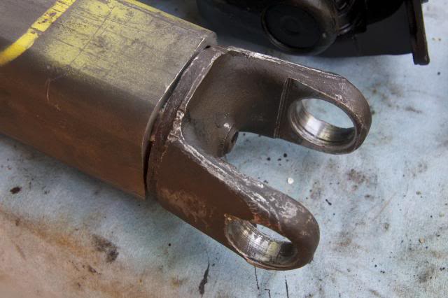
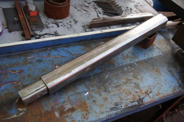
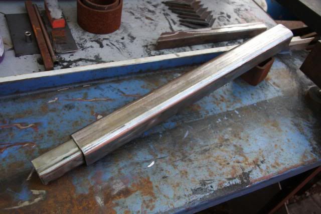
New plan via driveline angle info said I need a ( UJOINT ) at both ends of the front DS because of the flange angles. I used the U joint yoke cut of the rear and welded it to the front DS.
FRONT DS.
http://i561.photobucket.com/albums/s...psd7c83f57.jpg
http://i561.photobucket.com/albums/s...ps33d83754.jpg
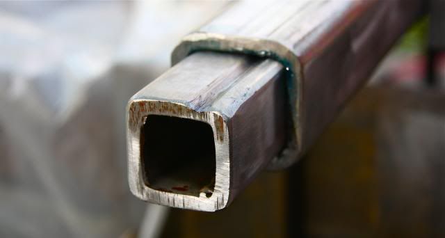
I had the U joint yoke machined to fit the 2.5 square DS.
http://i561.photobucket.com/albums/s...ps88ee28ad.jpg
I hope this helps,,,,,
That having been done I have no shake or off throttle growl.
Now to the front DS. I had originally set it up with the CV and U joint.
31.5 inches flange to flange....... but that was canned in that the CV went to the other end.
(rear)
New plan via driveline angle info said I need a ( UJOINT ) at both ends of the front DS because of the flange angles. I used the U joint yoke cut of the rear and welded it to the front DS.
FRONT DS.
http://i561.photobucket.com/albums/s...psd7c83f57.jpg
http://i561.photobucket.com/albums/s...ps33d83754.jpg
I had the U joint yoke machined to fit the 2.5 square DS.
http://i561.photobucket.com/albums/s...ps88ee28ad.jpg
I hope this helps,,,,,
Nov 7, 2013 | 07:18 PM
#25

Thread Starter
Registered User
Joined: Oct 2013
Posts: 30
Likes: 0
I thought I read that you used 2.5" tube with a seam and ground a groove in the inner tube. Was that because you weren't able to find seamless receiver tubing? I am just over the hill from you in Sonoma county.
 Nov 9, 2013 | 07:01 AM
#27
Thread Starter
Registered User
Joined: Oct 2013
Posts: 30
Likes: 0
 Nov 14, 2013 | 09:33 PM
#29
Thread Starter
Registered User
Joined: Oct 2013
Posts: 30
Likes: 0
I was able to pick up some tires the other day. I got them mounted on an old set of wheels from my chevy. I drove it around the block and am quite pleased with how it turned out. I need to get some paint on the bare metal, weld my sliders on, and get a front drive shaft and it'll be all set.
How it sits now
How it sits now
Nov 17, 2013 | 05:41 PM
#30
Thread Starter
Registered User
Joined: Oct 2013
Posts: 30
Likes: 0
Today I put welded 3rd with the 4.88 in the rear. I also installed the new pinion seal in the front 3rd member and will be putting that in very soon. I also installed the rock sliders I made a month ago.
The sliders

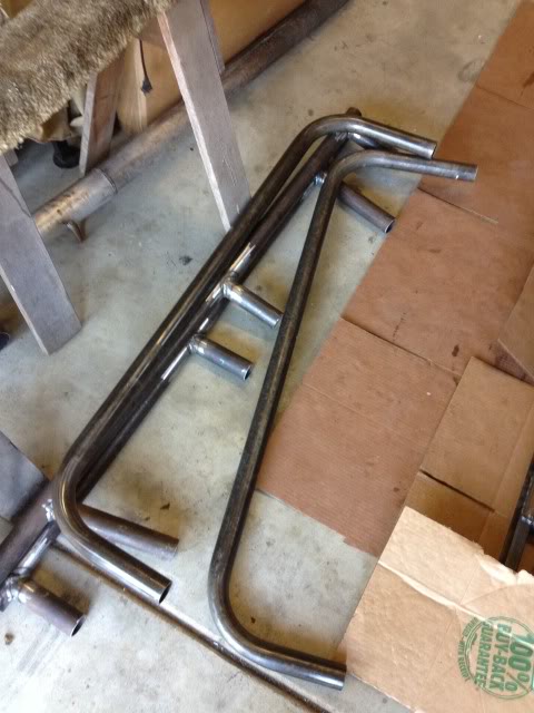


Then I went and found a small ledge to try to get the front and rear springs (mostly front) to settle and to check bump stop positioning.
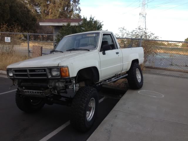
The truck as it sits now in the driveway

The sliders
Then I went and found a small ledge to try to get the front and rear springs (mostly front) to settle and to check bump stop positioning.
The truck as it sits now in the driveway


 Nov 24, 2013 | 07:56 PM
#34
Thread Starter
Registered User
Joined: Oct 2013
Posts: 30
Likes: 0
I spent a few hours making the bumpstops today. I reused the 4 bumpstops from the ifs for all four corners.
First I cut two pieces of 1 3/4 .120 dom for the front(short) and two for the rear(long). I then cut four 1 3/4 caps and welded a nut inside each one for the bumpstops to thread into. I then welded the caps to the tube and ended up with these.
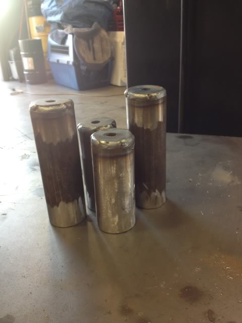
Then I threaded the bumpstops into the threaded tubes.

I feel that it's important to note that at this point my friend says "it looks like a penis". Hey, at least it's under the truck and not overly visible because by this point i was faiy commited to them. Lol
Finally I welded them to the frame. The fronts are perfect and contact slightly inboard on the spring plate. The rears are about an inch long but still contact slightly inboard on the spring plate. I positioned them so that the have a solid contact point during articulation.

I went and flexed it out a bit to check bump placement.

First I cut two pieces of 1 3/4 .120 dom for the front(short) and two for the rear(long). I then cut four 1 3/4 caps and welded a nut inside each one for the bumpstops to thread into. I then welded the caps to the tube and ended up with these.
Then I threaded the bumpstops into the threaded tubes.
I feel that it's important to note that at this point my friend says "it looks like a penis". Hey, at least it's under the truck and not overly visible because by this point i was faiy commited to them. Lol
Finally I welded them to the frame. The fronts are perfect and contact slightly inboard on the spring plate. The rears are about an inch long but still contact slightly inboard on the spring plate. I positioned them so that the have a solid contact point during articulation.
I went and flexed it out a bit to check bump placement.

Thread
Thread Starter
Forum
Replies
Last Post
Poncho0206
95.5-2004 Tacomas & 96-2002 4Runners
3
Jul 10, 2015 06:21 PM


