
Wiring tractor lights
 Oct 5, 2007 | 05:20 PM
#1
Thread Starter
Contributing Member
Joined: Feb 2007
Posts: 9,055
Likes: 10
From: maple ridge, British Columbia, Canada
Wiring tractor lights
Okay, I wanted to install my backup tractor lights that I had gotten for free.
Went to the local store and got:
50ft of 16gauge wire
80 crimp connectors
10 wire to wire connectors
12v 40 amp relay (draw picture posted below)
and a Blue lighted toggle switch
So I set about wiring them.
I ran a wire from the battery with a fuse ( think there was a 10amp fuse in there)
Ran that to the relay
Ran a wire from the relay to the power source on the switch
ran my ground for my switch
ran a wire back from the switch to the relay
then ran a wire back to my lights
when I first tried to turn it on I would get nothing.
The relay would click but nothing.
Ok, so I disconected the wire going back to the relay from the switch, so now there is only constant power and a ground on the switch, now my switch lights up.
and this is where I stopped, I have no idea where to go from here.
Can anyone just tell me what wires go where, I am no good at reading diagrams.
Here is a picture of the relay I got, sorry my camera is dead right now.
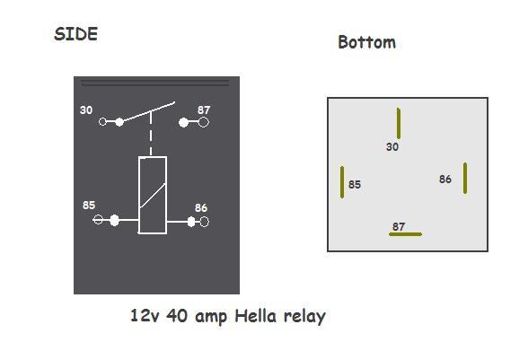
I was connecting the battery wire to the 86 prong
wire to my switch on the 85 prong
wire comming back from the switch on the 30 prong
then wire going to my lights on the 30 prong.
I dont think this is right. ideas?
Gonna try it again tomorrow afternoon
Went to the local store and got:
50ft of 16gauge wire
80 crimp connectors
10 wire to wire connectors
12v 40 amp relay (draw picture posted below)
and a Blue lighted toggle switch
So I set about wiring them.
I ran a wire from the battery with a fuse ( think there was a 10amp fuse in there)
Ran that to the relay
Ran a wire from the relay to the power source on the switch
ran my ground for my switch
ran a wire back from the switch to the relay
then ran a wire back to my lights
when I first tried to turn it on I would get nothing.
The relay would click but nothing.
Ok, so I disconected the wire going back to the relay from the switch, so now there is only constant power and a ground on the switch, now my switch lights up.
and this is where I stopped, I have no idea where to go from here.
Can anyone just tell me what wires go where, I am no good at reading diagrams.
Here is a picture of the relay I got, sorry my camera is dead right now.
I was connecting the battery wire to the 86 prong
wire to my switch on the 85 prong
wire comming back from the switch on the 30 prong
then wire going to my lights on the 30 prong.
I dont think this is right. ideas?
Gonna try it again tomorrow afternoon
Oct 5, 2007 | 05:27 PM
#2
Registered User
Joined: Oct 2006
Posts: 1,341
Likes: 0
From: Woodway, TX
Ditch the relay, you don't need it. Just make sure you keep the inline fuse from the power source.
Run a wire from the battery to the switch
Switch to the lights
Then, switch to ground, and ground your lights.........that should do it
Run a wire from the battery to the switch
Switch to the lights
Then, switch to ground, and ground your lights.........that should do it
Oct 5, 2007 | 05:31 PM
#4
Co-Founder/Administrator
iTrader: (1)
Joined: May 2002
Posts: 32,242
Likes: 22
From: Auburn, Washington
Jay, it has been awhile since I wired my tractor lamps, but they are wired up the same as my old Hellas.
Here was the write-up for the tractors.
https://www.yotatech.com/forums/f127...p-lamps-75744/
Here is a sheet with the relay on it.
https://www.yotatech.com/~corey/tech..._lamp_scan.jpg
It is from my Hella install.
https://www.yotatech.com/forums/f127...4runner-75274/
Hope this helps.
Doing the new install on my FJ Cruiser was easier, as the wires were connected to the relay in a kit IPF provides.
Oct 5, 2007 | 05:32 PM
#5
Registered User
Joined: Oct 2006
Posts: 1,341
Likes: 0
From: Woodway, TX
As long as you have an inline fuse you'll be fine. I have my power source running from an aux fuse box I installed under my hood. So I have a 20 amp fuse before it even sends power to the lights, then another 20amp fuse after that.
Oct 5, 2007 | 05:44 PM
#6
Thread Starter
Contributing Member
Joined: Feb 2007
Posts: 9,055
Likes: 10
From: maple ridge, British Columbia, Canada
Okay, I just want to be safe so im going to run the relay.
from what I understand I will run it like:
Battery to 30 prong on the relay ( should I change the 10amp fuse that I have inline with the battery? To say a 15 or more?
87 prong goes to the lights
85 prong goes to my switch
and the 86 prong is a ground.
Now I have 3 prongs on my switch, one is ground
one is power, then the middle one.
Do I leave that one alone?
In the hella instructions it goes to the headlights, but that has nothing to do with my install.
Oct 5, 2007 | 06:04 PM
#7
Co-Founder/Administrator
iTrader: (1)
Joined: May 2002
Posts: 32,242
Likes: 22
From: Auburn, Washington
Did you look how my old switches were wired?
Your third wire which Hella dictates to wire to the headlights is the trigger wire to activate the lamps.
You can wire that to 12v that is hot all the time, thus letting your new lamps come on anytime you want.
You can tap into your fusebox to a hot fuse, or a circuit that is hot only when the key is on.
Trending Topics
Oct 5, 2007 | 06:06 PM
#8
Thread Starter
Contributing Member
Joined: Feb 2007
Posts: 9,055
Likes: 10
From: maple ridge, British Columbia, Canada
to wire it to 12v would I just attach it to my positive battery termanel?
Do all switches have the same pattern?
like:
top = ground
middle = ??
bottom = power source
I had looked at all of your write ups but couldn't make any sence of it, but now that I have the parts it makes a little more sence.
I have everything pretty much figured out except for the middle prong thing.
Last edited by Jay351; Oct 5, 2007 at 06:07 PM.
Oct 5, 2007 | 06:11 PM
#9

I assume you are using a lit type switch. One tip when using those is to figure out how they work internally. While they have a power, ground and load connection, you need to figure out to what the load connection is connected to when the switch is on. That is, does the switch connect power or ground to the load. I think many are wired internally to connect power to the load (ground is for the internal light). So the other side of the relay coil needs to be grounded to complete the circuit.
Oct 5, 2007 | 06:23 PM
#10
Thread Starter
Contributing Member
Joined: Feb 2007
Posts: 9,055
Likes: 10
From: maple ridge, British Columbia, Canada
oh okay! I thought the ground on the switch grounded everything.
Yes it is a lit type switch
I just need to know, to set it up hot so it can come on anytime I want, I would route the middle prong on the switch directly to the battery?
I will give it another go tomorrow after work ( hopfally no rain!)
Yes it is a lit type switch
I just need to know, to set it up hot so it can come on anytime I want, I would route the middle prong on the switch directly to the battery?
I will give it another go tomorrow after work ( hopfally no rain!)
Oct 5, 2007 | 06:44 PM
#11
Contributing Member
Joined: Dec 2005
Posts: 2,226
Likes: 0
From: Houston (home), Atlanta (school), Cincinnati (work)
if you have an inline fuse then yes, itll still be a safe circuit (provided the fuse is close to the battery), but a problem that most people run into is finding a switch that can handle the direct voltage from the battery to the lights (or whatever device is being powered). thats where the relay comes in
Oct 5, 2007 | 08:08 PM
#12
Registered User
Joined: Sep 2007
Posts: 1,803
Likes: 1
From: Sweet Home, OR
I think your problem lies not with the switch but with the wiring of the relay-
Here is how my friend wired his:
We ran a wire from the + terminal on the battery through like a 5a fuse to a toggle switch in the dash, then the other wire from the switch to a terminal on the relay . We grounded another terminal via a self-tapping sheet metal screw. Next we ran a large wire with an 80A circuit breaker to the third terminal on the relay , and ran the last terminal to the lights. The other side of the lights we grounded.
Now, thats how we wired his, however his was using a simple 80A SPST-NO relay, yours may be different, but If i was to guess, i would say wire the switch inline with the battery and terminal 85, 86 goes to ground, 30 goes to battery with an inline fuse large enough to handle the load of the light(s), and 87 goes to the lights. The other side of the lights are grounded. As I said, it may be different, just an idea. I have used lighted switches before and I think when I did mine I ran my +12v in, switched 12v, and then a ground for the light.
Hope this helps.
Oct 5, 2007 | 08:29 PM
#13
Registered User
Joined: Sep 2007
Posts: 1,803
Likes: 1
From: Sweet Home, OR
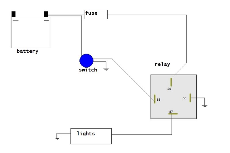
Okay, I made up a diagram for you-
for more security, you can fuse the link between the batt. and switch- I wouldn't because there is not that much current.
You will have to look at the diagram for the switch. You should have an "In" "appliance out" and "ground", connect accordingly.
for more security, you can fuse the link between the batt. and switch- I wouldn't because there is not that much current.
You will have to look at the diagram for the switch. You should have an "In" "appliance out" and "ground", connect accordingly.
Oct 5, 2007 | 09:37 PM
#14
I think your problem lies not with the switch but with the wiring of the relay-
Here is how my friend wired his:
We ran a wire from the + terminal on the battery through like a 5a fuse to a toggle switch in the dash, then the other wire from the switch to a terminal on the relay . We grounded another terminal via a self-tapping sheet metal screw. Next we ran a large wire with an 80A circuit breaker to the third terminal on the relay , and ran the last terminal to the lights. The other side of the lights we grounded.
Now, thats how we wired his, however his was using a simple 80A SPST-NO relay, yours may be different, but If i was to guess, i would say wire the switch inline with the battery and terminal 85, 86 goes to ground, 30 goes to battery with an inline fuse large enough to handle the load of the light(s), and 87 goes to the lights. The other side of the lights are grounded. As I said, it may be different, just an idea. I have used lighted switches before and I think when I did mine I ran my +12v in, switched 12v, and then a ground for the light.
Hope this helps.
Here is how my friend wired his:
We ran a wire from the + terminal on the battery through like a 5a fuse to a toggle switch in the dash, then the other wire from the switch to a terminal on the relay . We grounded another terminal via a self-tapping sheet metal screw. Next we ran a large wire with an 80A circuit breaker to the third terminal on the relay , and ran the last terminal to the lights. The other side of the lights we grounded.
Now, thats how we wired his, however his was using a simple 80A SPST-NO relay, yours may be different, but If i was to guess, i would say wire the switch inline with the battery and terminal 85, 86 goes to ground, 30 goes to battery with an inline fuse large enough to handle the load of the light(s), and 87 goes to the lights. The other side of the lights are grounded. As I said, it may be different, just an idea. I have used lighted switches before and I think when I did mine I ran my +12v in, switched 12v, and then a ground for the light.
Hope this helps.
Basically the same thing I was saying. If the switch is set up to switch power, then you need to ground the opposite side of the relay coil. If you just have a "plain old switch", then it can be wired any way you want. But if the switch is pre-wired internally for a built-in indicator light, you need to use it the way it was internally wired. Note that a lot of the Toyota factory switches are made to switch the ground side of a circuit, especially in the lighting circuits.
Oct 6, 2007 | 07:05 AM
#16
Registered User
Joined: Oct 2006
Posts: 1,341
Likes: 0
From: Woodway, TX
if you have an inline fuse then yes, itll still be a safe circuit (provided the fuse is close to the battery), but a problem that most people run into is finding a switch that can handle the direct voltage from the battery to the lights (or whatever device is being powered). thats where the relay comes in
Oct 6, 2007 | 11:09 AM
#17
Thread Starter
Contributing Member
Joined: Feb 2007
Posts: 9,055
Likes: 10
From: maple ridge, British Columbia, Canada


Wired it up, changed the fuse from a 10amp to a 15amp.
Shook the relay a little and they work!!
they are damn bright. I can't wait till some jerk off decides to tailgate me at night

Last edited by Jay351; Oct 6, 2007 at 02:14 PM.
Oct 6, 2007 | 04:11 PM
#18
Registered User
Joined: Oct 2006
Posts: 1,341
Likes: 0
From: Woodway, TX
 Oct 6, 2007 | 07:51 PM
#19
Thread Starter
Contributing Member
Joined: Feb 2007
Posts: 9,055
Likes: 10
From: maple ridge, British Columbia, Canada
all in all, it really was not that hard,just time consuming.I am prepared for the 2 sets of hella 500's that I ordered
I have to buy a soldering iron. I had a hell of a time crimping the little connectors on, they either would fall off or snap UGH.
where could I find a cheap one?
Im gonna have to install 2 more switches, but I dont have anymore of the removable little boxes (except one by the 4ways)
I was thinking of just mounting them beside the blue one, in a row closer to the steering wheel, ideas?
I was thinking of making a panel to go under my cd player so I could mount them there.
Last edited by Jay351; Oct 6, 2007 at 07:54 PM.
Oct 6, 2007 | 07:59 PM
#20
Registered User
Joined: Jun 2006
Posts: 462
Likes: 0
From: Corvallis Oregon OSU
id get on of those little cold hear sodering gun things, they work awesome and wont burn you and are baterry powered. Quite ingenious little things. Should be able to find a variety at lowes or home depot


