

Simple LED wited to a switch --- Why won't it work?!
 May 24, 2013 | 01:25 PM
#1

Thread Starter
Registered User
Joined: Feb 2013
Posts: 68
Likes: 17
From: Kauai, Hawaii
Simple LED wited to a switch --- Why won't it work?!
Hey guys,
I know there are a ton of threads that already talk about this mod, but I can't seem to find one that addresses my particular problem.
So I am wiring a few LEDs throughout my 92 Ext Cab Pickup, the first one up is an engine bay light.
I have installed an auxiliary fuse box under the hood, since I plan on installing multiple LEDs, I wanted to keep it as neat as possible and only have one wire tapped into the battery.
I also have an array of switches (3 prong, illuminated rocker switches) in the cab, this is where I plan to run all the LEDs to.
OK. So, I installed the LED under the hood. --- I can get the LED to work just fine without the switch, so I know that's not the problem. However I can't get the switch to function.
Here is how I have to wired, please help!
BATT POS --> AUX FUSE BOX
LED POS --> SWITCH POS #1 (on/off)
SWITCH POS #2 (LEAD) --> 5A FUSE in AUX FUSE BOX
LED NEG --> BATT NEG
SWITCH NEG --> GROUND
I have also tried this configuration: (just switched the two positive wires going into the switch)
BATT POS --> AUX FUSE BOX
LED POS --> SWITCH POS #2 (LEAD)
SWITCH POS #1 (on/off) --> 5A FUSE in AUX FUSE BOX
LED NEG --> BATT NEG
SWITCH NEG --> GROUND
What am I doing wrong here?
 May 24, 2013 | 02:34 PM
#3
Registered User
Joined: Apr 2011
Posts: 1,947
Likes: 1
From: Monkton, MD
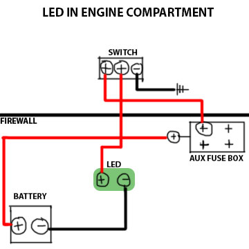
The wire from the fuse box should be going to the middle prong of the switch.
The only other thing I can think of is that the switch isn't rated for what you're using it for, which I highly doubt because LEDs draw such little current.
Here's a schematic I just found:
The only other thing I can think of is that the switch isn't rated for what you're using it for, which I highly doubt because LEDs draw such little current.
Here's a schematic I just found:
Last edited by 93Xtra-Cab; May 24, 2013 at 02:39 PM.
May 24, 2013 | 03:30 PM
#4

Registered User
Joined: May 2013
Posts: 78
Likes: 0
From: Vancouver, Wa
You might have burned it out, unless it was rated for 12v. They burn out VERY quickly if they are not wired to the correct power source. Even if it is rated for 12V, it might be a good idea to do the math and put a resister inline to ensure its getting the correct constant voltage. Use:
Resistance = ( (Vs) Power Supply Voltage - (Vf) LED Voltage Drop ) / (I)LED Current to determine the amount of resister you need.
Ex. If your LED's Forward voltage (Vf) is 3.5, and voltage drop is 20mA (I), and Power Supply is 12 then:
Resistance needed = (12 - 3.5) / .20 = 42.5 Ohms
That will limit the power to what that certain LED needs.
Just something to think about.
May 24, 2013 | 04:11 PM
#5
Thread Starter
Registered User
Joined: Feb 2013
Posts: 68
Likes: 17
From: Kauai, Hawaii
93xcab -
Thanks for that diagram, that is exactly how I have it wired. Yeah I wouldn't think anything is getting overloaded by a tiny LED. It must be something else.
Slo6i -
Thanks for the response, so you are saying that the switch might be burning out? It is designed for 12v, and I have 4 of them, all of which I have tried with the above configuration. Hopefully I didn't burn them all out? All that resistance math seems complicated, is there an easier way to do it without any special electrical tools? I don't have a voltmeter or anything like that.
May 24, 2013 | 04:32 PM
#6
Registered User
Joined: May 2013
Posts: 78
Likes: 0
From: Vancouver, Wa
93xcab -
Thanks for that diagram, that is exactly how I have it wired. Yeah I wouldn't think anything is getting overloaded by a tiny LED. It must be something else.
Slo6i -
Thanks for the response, so you are saying that the switch might be burning out? It is designed for 12v, and I have 4 of them, all of which I have tried with the above configuration. Hopefully I didn't burn them all out? All that resistance math seems complicated, is there an easier way to do it without any special electrical tools? I don't have a voltmeter or anything like that.
Thanks for that diagram, that is exactly how I have it wired. Yeah I wouldn't think anything is getting overloaded by a tiny LED. It must be something else.
Slo6i -
Thanks for the response, so you are saying that the switch might be burning out? It is designed for 12v, and I have 4 of them, all of which I have tried with the above configuration. Hopefully I didn't burn them all out? All that resistance math seems complicated, is there an easier way to do it without any special electrical tools? I don't have a voltmeter or anything like that.
May 24, 2013 | 04:47 PM
#7
Registered User
Joined: Apr 2011
Posts: 1,947
Likes: 1
From: Monkton, MD
^This. A link would definitely help.
Trending Topics
May 24, 2013 | 05:08 PM
#9
Registered User


Joined: Mar 2012
Posts: 7,133
Likes: 684


You might have burned it out, unless it was rated for 12v. They burn out VERY quickly if they are not wired to the correct power source. Even if it is rated for 12V, it might be a good idea to do the math and put a resister inline to ensure its getting the correct constant voltage. Use:
Resistance = ( (Vs) Power Supply Voltage - (Vf) LED Voltage Drop ) / (I)LED Current to determine the amount of resister you need.
Ex. If your LED's Forward voltage (Vf) is 3.5, and voltage drop is 20mA (I), and Power Supply is 12 then:
Resistance needed = (12 - 3.5) / .20 = 42.5 Ohms
That will limit the power to what that certain LED needs.
Just something to think about.
Resistance = ( (Vs) Power Supply Voltage - (Vf) LED Voltage Drop ) / (I)LED Current to determine the amount of resister you need.
Ex. If your LED's Forward voltage (Vf) is 3.5, and voltage drop is 20mA (I), and Power Supply is 12 then:
Resistance needed = (12 - 3.5) / .20 = 42.5 Ohms
That will limit the power to what that certain LED needs.
Just something to think about.
OR do you have component LED? In that case, you probably already blew it, unless you used a limiting resistor as slo6i mentioned above.
May 24, 2013 | 05:24 PM
#10
Registered User
Joined: Apr 2011
Posts: 1,947
Likes: 1
From: Monkton, MD
Do you have an LED Array already made to wire directly like in 93Xtra-Cab's schematic? If you do, you just need to make sure you connect in right polarity
OR do you have component LED? In that case, you probably already blew it, unless you used a limiting resistor as slo6i mentioned above.
OR do you have component LED? In that case, you probably already blew it, unless you used a limiting resistor as slo6i mentioned above.
I still think the problem is in the switch. He says in the first post that it works fine unless it is hooked up to the switch.
 May 24, 2013 | 06:32 PM
#11
Thread Starter
Registered User
Joined: Feb 2013
Posts: 68
Likes: 17
From: Kauai, Hawaii
If it is one of those LED strips, make sure the wires are still connected. I got a couple off of eBay once and I had to re-solder one of the wires back on. Just a thought.
I still think the problem is in the switch. He says in the first post that it works fine unless it is hooked up to the switch.
I still think the problem is in the switch. He says in the first post that it works fine unless it is hooked up to the switch.
I bought a few of these for my dome light, they are SO bright its rediculous. The leftovers are going in the engine bay.
And guys, the LED is fine, it works perfectly without the switch involved.
May 24, 2013 | 06:42 PM
#12
Thread Starter
Registered User
Joined: Feb 2013
Posts: 68
Likes: 17
From: Kauai, Hawaii
And here is the link for the switch if it helps http://www.pepboys.com/product/detai...36/?quantity=1
May 24, 2013 | 07:26 PM
#13
Registered User
Joined: May 2013
Posts: 78
Likes: 0
From: Vancouver, Wa
Yeah, those little wafer boards should already have the resistors in them if they are specifying a 12v power source.
My only guess is that the wiring to the switch is wrong.
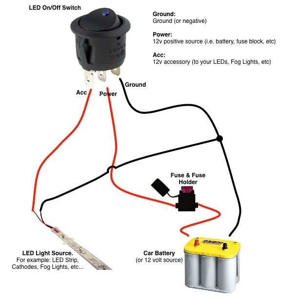
It looks as though that switch is setup differently than the one xcab posted. looks like the constant 12v goes on one of the outside terminals.
You might also try wiring it inline with the supply wire or the ground wire to open the circuit.
My only guess is that the wiring to the switch is wrong.
It looks as though that switch is setup differently than the one xcab posted. looks like the constant 12v goes on one of the outside terminals.
You might also try wiring it inline with the supply wire or the ground wire to open the circuit.
Last edited by slo6i; May 24, 2013 at 07:31 PM.
May 24, 2013 | 10:12 PM
#14
Registered User
Joined: Mar 2012
Posts: 7,133
Likes: 684
Yeah, those little wafer boards should already have the resistors in them if they are specifying a 12v power source.
My only guess is that the wiring to the switch is wrong.
It looks as though that switch is setup differently than the one xcab posted. looks like the constant 12v goes on one of the outside terminals.
You might also try wiring it inline with the supply wire or the ground wire to open the circuit.
My only guess is that the wiring to the switch is wrong.
It looks as though that switch is setup differently than the one xcab posted. looks like the constant 12v goes on one of the outside terminals.
You might also try wiring it inline with the supply wire or the ground wire to open the circuit.
"Supply Volts" and "On Access" are not polarized; they are just contacts that open or close, so XCab's wiring should still work.
However, OP should verify from instructions that came with LED which lead is + and which one is -.
Then to be clear, wire it this way:

Last edited by RAD4Runner; May 25, 2013 at 12:45 AM. Reason: Added fuse and voltage test points
May 24, 2013 | 11:56 PM
#15
Registered User
iTrader: (1)
Joined: Apr 2009
Posts: 13,381
Likes: 100
From: I live in New Tripoli Pa out in the woods
First thing to do is check that the switch works. This seems to be more of a problem all the time.
make sure the fuse holder holds the fuse tight.
check all the connections.
Break out the Multimeter check for voltage.at the different connections
make sure the fuse holder holds the fuse tight.
check all the connections.
Break out the Multimeter check for voltage.at the different connections
May 28, 2013 | 02:39 PM
#17
Thread Starter
Registered User
Joined: Feb 2013
Posts: 68
Likes: 17
From: Kauai, Hawaii
Thanks for checking, XCab. Actually I was just working on it last night after work, and no, the only thing I got out of it was another headache.
So I wired it up just like in RAD4Runner's diagram. I made sure the switch was working because I used the same one I have my inverter wired to, I just unplugged the inverter for the time being.
So with all the wiring set up exactly like in RAD4s diagram, the tiny light in the illuminated properly when flipped into the on position, but the LED did not.
Still very confused.
May 28, 2013 | 03:07 PM
#18
Registered User
Joined: May 2013
Posts: 78
Likes: 0
From: Vancouver, Wa
This is the point where you would bust out the multimeter, or test light, and make sure you are getting voltage through the fuse, through the switch, to the + on the board, to the negative of the board and back to battery. You can also confirm that the switch does indeed work. (It worked yesterday is not a good way of diagnosing problems.)
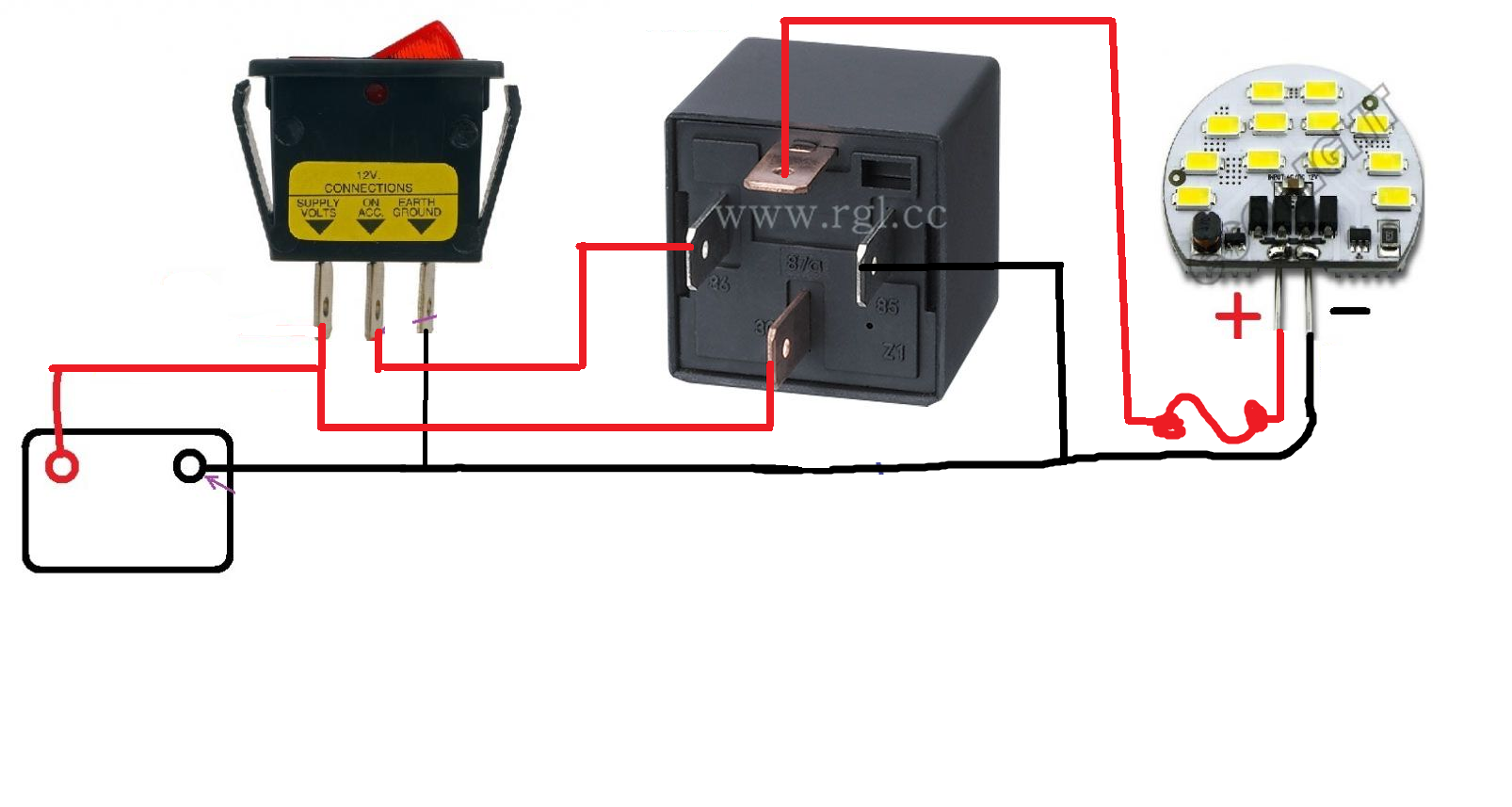
The only thing that I can think of is that the switch is causing enough resistance to not fire the LED's, but that seems a little ridiculous. Next option is to wire in a relay that breaks the circuit to the led's directly, and use the switch to trigger the relay, rather than run the led power through the switch.

The only thing that I can think of is that the switch is causing enough resistance to not fire the LED's, but that seems a little ridiculous. Next option is to wire in a relay that breaks the circuit to the led's directly, and use the switch to trigger the relay, rather than run the led power through the switch.
Last edited by slo6i; May 28, 2013 at 03:39 PM.
May 28, 2013 | 03:51 PM
#19
Registered User
Joined: Mar 2012
Posts: 7,133
Likes: 684
Yeah.
Cartercoulombe, when was the last time you tested the LED? Should work when connected directly to the battery. When it does mark the + and the - pins right away
Correct, and that means switch is bad. Throw it away.
Don't know, man. LED should not need all that. Something must be defective in the system.
Cartercoulombe, when was the last time you tested the LED? Should work when connected directly to the battery. When it does mark the + and the - pins right away
The only thing that I can think of is that the switch is causing enough resistance to not fire the LED's, but that seems a little ridiculous.
Next option is to wire in a relay that breaks the circuit to the led's directly, and use the switch to trigger the relay, rather than run the led power through the switch.
May 28, 2013 | 04:05 PM
#20
Registered User
Joined: May 2013
Posts: 78
Likes: 0
From: Vancouver, Wa


