

87 4Runner Rear Window Issues - Motor is fine


 Jun 29, 2013 | 11:53 AM
#22

Thread Starter
Registered User
Joined: Jan 2012
Posts: 193
Likes: 0
From: New Mexico
Limit switch is good!
I fixed the lock switch! Didn't change anything.
I jumped 4-11 and 5-12 on the relay. When I pressed the up/down button the relay click away but the window didn't budge.
On the off chance the up/down switch was dirty I took it apart which was a bad mistake. Pieces exploded everywhere. It was dirty but now I am missing most of the pieces to it.
SIGH
I'll check the 6 and 8 pin for power. Just a volt meter plug in? Or a 12V light?
Jun 29, 2013 | 02:23 PM
#24
Thread Starter
Registered User
Joined: Jan 2012
Posts: 193
Likes: 0
From: New Mexico
Double checked to make sure where are getting power to the relay but not to the back motor.
Yup, that's the case.
Up/down switch tests out fine but not at the relay. I am guessing maybe the disconnected it somewhere so it wouldn't talk to the relay and only to the dash switch.
Somewhere between the up/down and the relay is one of our problems.
Yup, that's the case.
Up/down switch tests out fine but not at the relay. I am guessing maybe the disconnected it somewhere so it wouldn't talk to the relay and only to the dash switch.
Somewhere between the up/down and the relay is one of our problems.
Jun 29, 2013 | 04:49 PM
#26
Registered User


Joined: Mar 2012
Posts: 7,124
Likes: 681
Good!
Don't jump 4 to 11 and 5 to 12 on the relay. Follow these exact steps one at a time:
Leave everything connected.
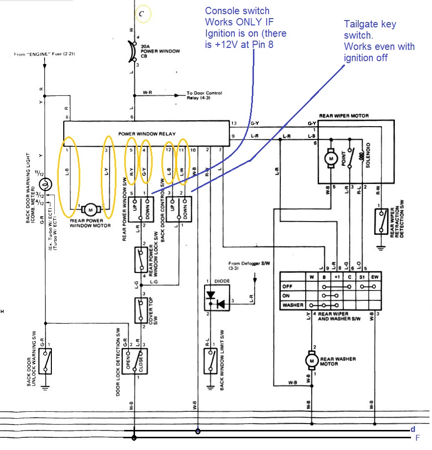
Short Pin 4 (Green-Yellow Stripe wire) to chassis ground. Relay should click and, there should be voltage across pins 1 & 3. That voltage should go to motor, and glass should go down.
Short pin 5 (red with yellow stripe wire) to chassis ground. Relay should click and, there should be voltage across pins 1 & 3. That voltage should be opposite polarity of voltage in (1). That voltage should go to motor, and glass should go up.
Do same, one at a time, with with pins 11 & 12. Should get same results as 1 & 2.
This test is INdependent of state of window lock switch or cover top switch. All relay module is looking for is Up/Down switch connection to ground AND proper state of limit switches for safety.
Next to our senses (Hear if engine's running smoothly? Smell or see coolant leak? Feel steering wheel vibrate? Hear and feel relays click? See spark? Hear grinding sound in transmission?), a multi-meter is the best diagnostic tool for classic 4Runners. I suggest you get one. HF is your friend 
Don't worry about the up/down switches, yet. Focus on testing relay module functionality and correct wiring. Schematic ^^ is all you need to verify your wiring. I recommend doing it cleanly, and not be ghetto like previous owners
Leave everything connected.
Short Pin 4 (Green-Yellow Stripe wire) to chassis ground. Relay should click and, there should be voltage across pins 1 & 3. That voltage should go to motor, and glass should go down.
Short pin 5 (red with yellow stripe wire) to chassis ground. Relay should click and, there should be voltage across pins 1 & 3. That voltage should be opposite polarity of voltage in (1). That voltage should go to motor, and glass should go up.
Do same, one at a time, with with pins 11 & 12. Should get same results as 1 & 2.
This test is INdependent of state of window lock switch or cover top switch. All relay module is looking for is Up/Down switch connection to ground AND proper state of limit switches for safety.
I'll check the 6 and 8 pin for power. Just a volt meter plug in? Or a 12V light?
Can't find all the pieces for the up/down switch, looks like a trip to the parts yard tomorrow to find a replacement.
Jun 29, 2013 | 05:35 PM
#27
Thread Starter
Registered User
Joined: Jan 2012
Posts: 193
Likes: 0
From: New Mexico
I really didn't understand, I think I got it but something shorted out.
First Relay
Short Pin 4 - no click, no window movement
Short Pin 5 - no click, no window movement
Short Pin 11 - click, no window movement
Short Pin 12 - click, no window movement
Second relay:
Short Pin 4 - no click, no window movement
Short Pin 5 - no click, no window movement
Short Pin 12 - no click, spark, key left in buzzer constantly on and check engine light disappeared as long as Ig is on. If I start the 4runner the buzzer keeps going. Guess I blew a fuse somewhere. Gotta go track that down.
Yes, I am that bad with electrical stuff. Pretty sure I screwed this up, more so.
Jun 29, 2013 | 08:30 PM
#29
Registered User
Joined: Mar 2012
Posts: 7,124
Likes: 681
No worries; always a pleasure to help.
First Relay
Short Pin 4 - no click, no window movement
Short Pin 5 - no click, no window movement
Short Pin 11 - click, no window movement
Short Pin 12 - click, no window movement
Second relay:
Short Pin 4 - no click, no window movement
Short Pin 5 - no click, no window movement
Short Pin 12 - no click, spark, key left in buzzer constantly on and check engine light disappeared as long as Ig is on. If I start the 4runner the buzzer keeps going. Guess I blew a fuse somewhere. Gotta go track that down.
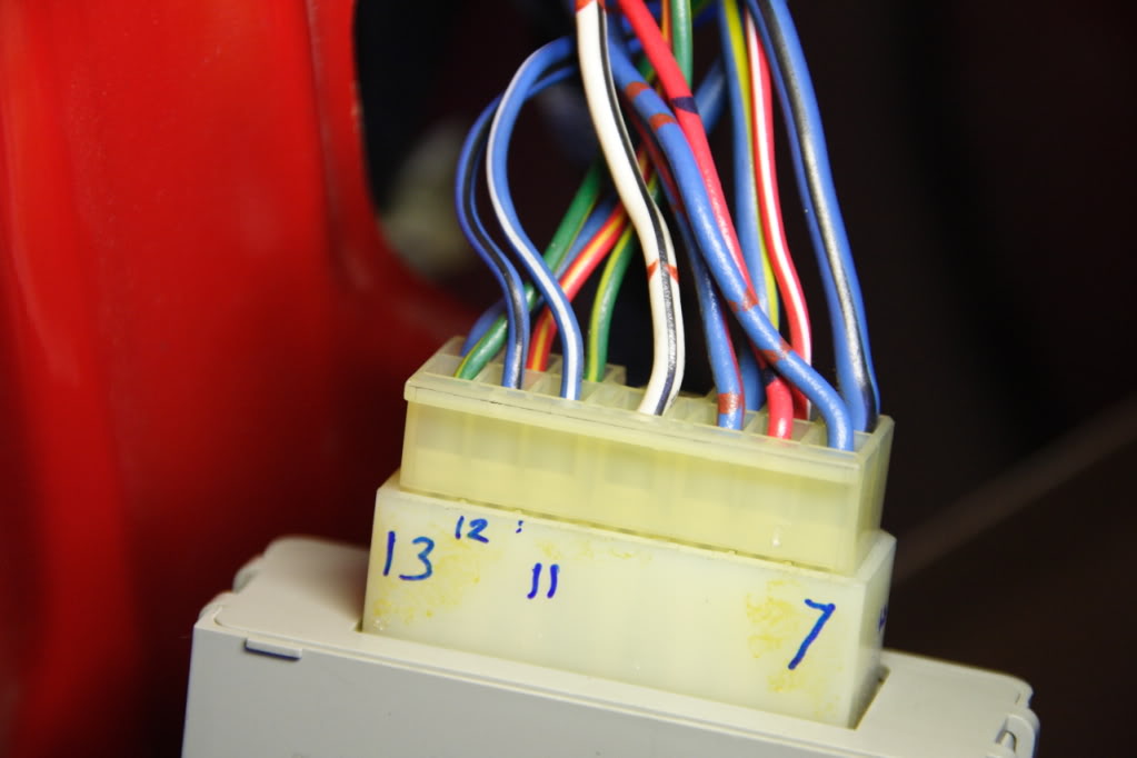
hmmm... you're working with 2 relay modules? Unless you're sure the second relay is good, you're only complicating matters, and makes troubleshooting confusing.
You should only be working on the squarish relay module in pic below and on pins I have enclosed in yellow below.
You were shorting pins directly to chassis ground, correct?
Results of first relay suggests that:
There is power to pin 6 through Circuit breaker, BUT
there is no power to pin 8 (or ignition is off).
First Relay
Short Pin 4 - no click, no window movement
Short Pin 5 - no click, no window movement
Pins 4 & 5 are input from console switch. These pins require that ignition be on, meaning that pin 8 has 12V. Did you verify that?
Short Pin 11 - click, no window movement
Short Pin 12 - click, no window movement
Clicking indicates that relay logic is good.
Even with no power to pin8 (or ign off), tailgate switch would work. Relay clicking means they are closing to send power to motor. As mentioned ^^ there should be voltage between pins 1 (blue with blk stripe) & 3 (blu & yel stripe). Did you check that?
Did you measure voltage between those pins? THIS IS VERY IMPORTANT. Shorting pin 11 or 12 to ground (one at a time, never simultaneously) will produce different output polarity.
First Relay
Short Pin 4 - no click, no window movement
Short Pin 5 - no click, no window movement
Short Pin 11 - click, no window movement
Short Pin 12 - click, no window movement
Second relay:
Short Pin 4 - no click, no window movement
Short Pin 5 - no click, no window movement
Short Pin 12 - no click, spark, key left in buzzer constantly on and check engine light disappeared as long as Ig is on. If I start the 4runner the buzzer keeps going. Guess I blew a fuse somewhere. Gotta go track that down.
You should only be working on the squarish relay module in pic below and on pins I have enclosed in yellow below.
You were shorting pins directly to chassis ground, correct?
Results of first relay suggests that:
There is power to pin 6 through Circuit breaker, BUT
there is no power to pin 8 (or ignition is off).
First Relay
Short Pin 4 - no click, no window movement
Short Pin 5 - no click, no window movement
Pins 4 & 5 are input from console switch. These pins require that ignition be on, meaning that pin 8 has 12V. Did you verify that?
Short Pin 11 - click, no window movement
Short Pin 12 - click, no window movement
Clicking indicates that relay logic is good.
Even with no power to pin8 (or ign off), tailgate switch would work. Relay clicking means they are closing to send power to motor. As mentioned ^^ there should be voltage between pins 1 (blue with blk stripe) & 3 (blu & yel stripe). Did you check that?
Did you measure voltage between those pins? THIS IS VERY IMPORTANT. Shorting pin 11 or 12 to ground (one at a time, never simultaneously) will produce different output polarity.
Last edited by RAD4Runner; Jun 29, 2013 at 08:32 PM.
Jun 30, 2013 | 04:08 AM
#30
Thread Starter
Registered User
Joined: Jan 2012
Posts: 193
Likes: 0
From: New Mexico
Just to make sure I am doing this correctly to measure the voltage between 1 and 3 I plug in the voltmeter to 1 and 3 with everything connected?
Or do I test them one at a time?
Thanks!
Or do I test them one at a time?
Thanks!
Jun 30, 2013 | 06:16 AM
#31
Thread Starter
Registered User
Joined: Jan 2012
Posts: 193
Likes: 0
From: New Mexico
From yesterday I wrote down a -12 V coming across pin 8.
This morning I am getting a -0.8V coming across pin 8 with Ig on. I need to figure out what I shorted out last night that is causing the buzzer to go off constantly with the key in. Also some of the dash lights disappeared.
There is also an ugly mass of wiring in the front under the radio where the added amp is. I haven't touched that yet.
Jun 30, 2013 | 06:31 AM
#33
Thread Starter
Registered User
Joined: Jan 2012
Posts: 193
Likes: 0
From: New Mexico
Window Relay Recheck
Pin 8, IG on, is reading -12V
Short Pin 4 - no click, no window movement
Short Pin 5 - no click, no window movement
Short Pin 11 - click, no window movement
Short Pin 12 - click, no window movement
Pin 8, IG on, is reading -12V
Short Pin 4 - no click, no window movement
Short Pin 5 - no click, no window movement
Short Pin 11 - click, no window movement
Short Pin 12 - click, no window movement
Jun 30, 2013 | 06:37 AM
#34
Thread Starter
Registered User
Joined: Jan 2012
Posts: 193
Likes: 0
From: New Mexico
Pin 1-3 Voltage Check
IG off, 0 V
IG on, 0 V
Suppose to PO cut the IG wire to the relay somewhere to route to the dash switch. I am kicking myself for not paying closer attention to how the dash switch was rigged up.
IG off, 0 V
IG on, 0 V
Suppose to PO cut the IG wire to the relay somewhere to route to the dash switch. I am kicking myself for not paying closer attention to how the dash switch was rigged up.
 Jun 30, 2013 | 11:06 AM
#36
Registered User
Joined: Mar 2012
Posts: 7,124
Likes: 681
Negative 12V?
Here polarity is critical.
Voltmeter in Volts DC setting,
Black (Neg) probe to chassis ground,
Red (Pos) probe to pin 8
You should get +12V, not -12V
You should measure voltage when relay clicks, when it's supposed to be sending power to pins 1 & 3. Voltmeter set to Volts DC, one probe on pin 1 one probe on pin3. Polarity not critical because it will reverse with UP/ or down direction.
As I said you should get voltage between 1 & 3 when relay clicks. If you do but motor does not run, check wiring to motor per schematic.
Modification is OK IF, and only IF, it's robust, it works and you're comfortable with wiring. Otherwise, stick to stock. Obviously, P.O.'s dash switch is ghetto- that's why you're having a problem with it. Better to bypass it, do it right by re-wiring according to schematic. This will make it easier for others to help you troubleshoot - especially remotely.
Here polarity is critical.
Voltmeter in Volts DC setting,
Black (Neg) probe to chassis ground,
Red (Pos) probe to pin 8
You should get +12V, not -12V
You should measure voltage when relay clicks, when it's supposed to be sending power to pins 1 & 3. Voltmeter set to Volts DC, one probe on pin 1 one probe on pin3. Polarity not critical because it will reverse with UP/ or down direction.
As I said you should get voltage between 1 & 3 when relay clicks. If you do but motor does not run, check wiring to motor per schematic.
Suppose to PO cut the IG wire to the relay somewhere to route to the dash switch. I am kicking myself for not paying closer attention to how the dash switch was rigged up.
Last edited by RAD4Runner; Jun 30, 2013 at 11:09 AM.
Jun 30, 2013 | 02:54 PM
#38
Thread Starter
Registered User
Joined: Jan 2012
Posts: 193
Likes: 0
From: New Mexico
I removed all the dash wiring so we should be stock condition now. They had plugged directly into the motor bypassing all the stock wiring. Also some of the wires from the dash switch were plugged into the driver side fuse box.
I test all the relays and switches and the motor in the system and then plugged it all back together.
I test all the relays and switches and the motor in the system and then plugged it all back together.
Jun 30, 2013 | 03:46 PM
#39
Thread Starter
Registered User
Joined: Jan 2012
Posts: 193
Likes: 0
From: New Mexico
Think I got it right this time!!!
Pin 8 - +12V
Voltmeter in 1-3
Pin 11 to G - click, no voltage across 1-3
Pin 12 to G - click, no voltage across 1-3
Pin 4 to G - no click, no voltage across 1-3
Pin 5 to G - no click, no voltage across 1-3
Pin 8 - +12V
Voltmeter in 1-3
Pin 11 to G - click, no voltage across 1-3
Pin 12 to G - click, no voltage across 1-3
Pin 4 to G - no click, no voltage across 1-3
Pin 5 to G - no click, no voltage across 1-3
Jun 30, 2013 | 08:20 PM
#40
Registered User
Joined: Mar 2012
Posts: 7,124
Likes: 681
Sounds like you got things back to stock, which is good.Symptoms above suggest that:
- Limit switches are in correct states to allow window to roll up or down. Please verify limit switch functionality by leaving tail gate down, and trying to make relay click (using 11 & then 12). Then, leaving wiper in wiping position and trying to make relay click (using 11 & then 12), etc.
- Internal to relay module, IGN voltage from Pin 8 is not going to logic. That's why console switch logic (pins 4 / 5 ) does not allow Up/Down
- Internal to relay module, power from pin 6 (always on as long as battery is connected and charged) is not getting to motor drive relay (the one that clicks)
At this point, it looks like a defective relay module. Many members have mentioned bad module due to oxidation from exposure to environment (i.e., when top is removed and module gets wet).
I would:
Take relay module apart and inspect for loose/broken/oxidized connections or cold solder- especially where IGN voltage and Pin6 voltage pass.
It would really be nice if fellow members can share internal schematic of rear window relay module, if it exists. This would help greatly with this common problem.
For example, I presume that (need to verify this through internal schematic):
- Motor drive relay only clicks IF and only IF limit switches indicate conditions, and
- sensor switches do not interrupt actual drive power to motor, therefore, as soon as motor drive relays click, there should be voltage at pins 1-3


