
Successful '93 OBD Reading
 Dec 14, 2014 | 01:08 PM
#21

Registered User

Joined: Sep 2007
Posts: 8,384
Likes: 875
From: San Francisco East Bay
jg -
How did you connect to VSS and INJ? I'm terribly afraid of commitment (?!), so I didn't want to be cutting up my harness to splice in sensor wires. So, as a half-way measure, I used 22ga telephone wire, inserted into the back of the connector until it was just 'touching' the conductor, and then anchored with hot-melt glue. It's held for about 20 miles of testing (I wish I could say the same for the connector at the other end.)
My hope is that I can just pull it off the connector without harm, should I get cold feet.
Dec 14, 2014 | 03:35 PM
#22

data logger
I thought I saw this on Yotatech board while doing searches. Some Russian wrote some software and made a cable to get the data you are looking for.
I also found a Lexus site that references the same software/cable
-> http://www.clublexus.com/forums/perf...ger-found.html
I built the cable and ran the software. though some of the readings looked off, this may get you guys/gals what you want without a lot of effort.
I also found a Lexus site that references the same software/cable
-> http://www.clublexus.com/forums/perf...ger-found.html
I built the cable and ran the software. though some of the readings looked off, this may get you guys/gals what you want without a lot of effort.
Dec 14, 2014 | 11:19 PM
#23
Registered User
Joined: Sep 2014
Posts: 507
Likes: 8
From: LA CA
jg -
How did you connect to VSS and INJ? I'm terribly afraid of commitment (?!), so I didn't want to be cutting up my harness to splice in sensor wires. So, as a half-way measure, I used 22ga telephone wire, inserted into the back of the connector until it was just 'touching' the conductor, and then anchored with hot-melt glue. It's held for about 20 miles of testing (I wish I could say the same for the connector at the other end.)
My hope is that I can just pull it off the connector without harm, should I get cold feet.
How did you connect to VSS and INJ? I'm terribly afraid of commitment (?!), so I didn't want to be cutting up my harness to splice in sensor wires. So, as a half-way measure, I used 22ga telephone wire, inserted into the back of the connector until it was just 'touching' the conductor, and then anchored with hot-melt glue. It's held for about 20 miles of testing (I wish I could say the same for the connector at the other end.)
My hope is that I can just pull it off the connector without harm, should I get cold feet.
For this project though, oh how I would love to find a male and female terminal for the ecu so an easy plug-in piggyback could be attached in series and all sensing done from a piggyback box. Plug and play style... I suspect the only way to find those components would be stealing from an existing ecu and harness. Meh
Catwrangler- that is really neat, but I think what some of the guys are saying here is that it's only for cars with the later diagnostic ports- supposedly nonexistent in earlier models. A direct line sensing approach would mean compatibility across all years and higher time resolution, both parts being very appealing to me! How is the refresh rate on the one you have there? Is it at around 1sec intervals or much faster?
Dec 15, 2014 | 05:53 AM
#24
Successful '93 OBD Reading
Jennygirl, The method I mentioned applies to some 86 and all 87 and up Toyotas with DLC1(OBD1) connector. OP says 93 4runner, same as mine. The refresh time is faster than 1 sec, not sure exactly how fast. Perhaps I'll hook it up today and take a snapshot.
In addition to the Russians I ran across a guy that looks like he compressed Russian work and the cable down to a stamp type device and used bluetooth to get the data to an Android app. Here is a link.
http://jfbreton.blogspot.com/2014/10...er-how-to.html
Maybe not what everyone is looking for, but it might save some time/energy.
Dec 15, 2014 | 09:16 AM
#25

Registered User
Joined: Jul 2012
Posts: 1,776
Likes: 110
From: Northern Colorado
There are 119 bits in the data stream, and each bit is 8.192 mSec. So, the maximum refresh rate is once every 975 mSec, essentially once/second. Sorry, I miscounted the data stream. There are actually 163 bits in the stream, for a total update time of 1.34 Sec, or about .75 updates per second.
I think the data port was phased in at different times on various models of Toyotas. The Lexus and Supra models probably got the update sooner than the lowly 4runners and pickups. You'd have to investigate your particular ECU and see if it has the VF1 and TE2 terminals, and if they are active, even if the diag connector does not bring them out.
Here is the protocol description of the data stream. See my code referenced above for some idiosyncracies in terms of interpreting the data. In particular the VAFM and the ECT data needs some adjustment to be meaningful. Also, just as an FYI, the data comes out LSB first, which is typical of serial UART data, I think. A standard UART with a baud rate of 122Hz would be able to read the data directly, except for the leading 4 bit word after the start bits, which will confuse the UART. That's why I had to write my own code to parse the bit stream.
Last edited by RJR; Dec 15, 2014 at 10:23 AM.
Dec 15, 2014 | 05:15 PM
#27

Registered User
Joined: Dec 2014
Posts: 9
Likes: 0
From: Quebec, Canada
here`s videos showing the app
there is a graph mode and text display mode, export and import data to csv or export to cartester8000
I recently added a trip computer
I started a user FB group for toyobd1 users or enthusiasts
https://www.facebook.com/groups/1505898572959292/
here`s a log for the 3vz-e idling( on the fb group files)
https://www.facebook.com/groups/4111193745/files/
last summer when I posted on facebook ont the 4Runner group about this no one cared at all. It surprise me a lot that NOW there are people with 22r and 3vz-e interested in this...
there is a graph mode and text display mode, export and import data to csv or export to cartester8000
I recently added a trip computer
I started a user FB group for toyobd1 users or enthusiasts
https://www.facebook.com/groups/1505898572959292/
here`s a log for the 3vz-e idling( on the fb group files)
https://www.facebook.com/groups/4111193745/files/
last summer when I posted on facebook ont the 4Runner group about this no one cared at all.
It surprise me a lot that NOW there are people with 22r and 3vz-e interested in this...
Dec 15, 2014 | 07:08 PM
#29
Registered User
Joined: Sep 2014
Posts: 507
Likes: 8
From: LA CA
Lol, that is awesome. I would have loved to have that when I had my 3vzfe camry!
I do see that what RJR has been saying about the refresh time.. it holds true with your app's data logging method as well.
With a direct voltage sensing line, I hope to make that a very fluid constantly updating graph. Just ordered my 128x64 ks0108 glcd last night, and I'm going to be driving it with an arduino mega which has loads of ADC's. Enough to cover about every sensor going to the ECU
Thanks for posting the vids, I really like the multicolor logging graph. While my glcd will be monochrome, I hope to do something similar with a graph type display. Might even run dual screens!
Dec 15, 2014 | 07:47 PM
#30
Registered User
Joined: Dec 2014
Posts: 9
Likes: 0
From: Quebec, Canada
thanks Jenny, happy to see projects for the pre obd1 data stream ecus.
You could take your readings inside the ecu at the ADC and other procs,would make for a clean stealth wiring job,

or even more extreme we could all join efforts to decipher the communication protocol between ADC and Main proc. lots of those old toyota ecus have this main proc-adc relationship, it could be handy in many ecus to impletement new custom logic from a third party MCU and cleaner to implement(3 wires from what I saw in a 3e-e ecu instead of one wire for every sensor present AND save analog pins for something not available through digital data...)
why not transmid data over serial and use a phone as a `video card' for your hardware interface?
If you can write for the arduino, You probably can do in java.
your design would not become obsolete for a much longer time (say someone port the phone interface to another platform in X years),would cost less to build,less power consumption to the car ,easier to build,reach more people with bad or no electronic skills,use the free processing power that is present in everyone pocket atm, +logging capabilities and improve the app feature sets as time goes without the need to update the firmware.
it is surprising what people ask for my app as time goes by. As I record every variable received I can analyze a lot of things and come up with more calculated stuff. making the 1,3s delay not so bad after all...
You could take your readings inside the ecu at the ADC and other procs,would make for a clean stealth wiring job,
or even more extreme we could all join efforts to decipher the communication protocol between ADC and Main proc. lots of those old toyota ecus have this main proc-adc relationship, it could be handy in many ecus to impletement new custom logic from a third party MCU and cleaner to implement(3 wires from what I saw in a 3e-e ecu instead of one wire for every sensor present AND save analog pins for something not available through digital data...)
why not transmid data over serial and use a phone as a `video card' for your hardware interface?
If you can write for the arduino, You probably can do in java.
your design would not become obsolete for a much longer time (say someone port the phone interface to another platform in X years),would cost less to build,less power consumption to the car ,easier to build,reach more people with bad or no electronic skills,use the free processing power that is present in everyone pocket atm, +logging capabilities and improve the app feature sets as time goes without the need to update the firmware.
it is surprising what people ask for my app as time goes by. As I record every variable received I can analyze a lot of things and come up with more calculated stuff. making the 1,3s delay not so bad after all...
Dec 16, 2014 | 12:38 AM
#31
Registered User
Joined: Sep 2014
Posts: 507
Likes: 8
From: LA CA
I would have loved a 3 wire approach, but here is kinda what I had in mind. Looking at it like this, it seems a bit involved for what it's going to do- but it will be compatible with all years and have a stellar refresh time.
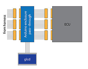
The biggest thing I like about arduino vs. a mobile OS app/laptop program interface is that it doesn't have to be updated as new phone OS's come out nor does it need external hardware. Get it right once and it's done forever, permanently installed in the car. No need to have an external device hooked up to it to get a read on what is going on. Plus the arduino consumes barely any power, same for the lcd screen (I already have two arduinos in my truck- one for my rgb dash lights and one for miles per gallon logging "mpguino"). I believe the Arduino Mega draws about 65mA.
Ideally this is a plug and play thing, with no electronics knowledge needed whatsoever. Unplug the connectors from the ecu and plug them into the enclosure, plug the pass through from the enclosure to the ecu, and connect the lcd screen. Easier than pie The Arduino and lcd screen are powered directly in parallel from the battery positive line that goes to the ECU. Firmware updates are easy with the cross platform Arduino program and a usb cable, also totally open source and easy to customize the display(s).
The one issue I can possibly see is cost- unless those ecu connectors can be sourced on the cheap. Megasquirt seems to have found them with their 22re plug-and-play standalone box. Any of you guys have any idea where they can be bought new rather than tearing apart a harness + ECU?

The biggest thing I like about arduino vs. a mobile OS app/laptop program interface is that it doesn't have to be updated as new phone OS's come out nor does it need external hardware. Get it right once and it's done forever, permanently installed in the car. No need to have an external device hooked up to it to get a read on what is going on. Plus the arduino consumes barely any power, same for the lcd screen (I already have two arduinos in my truck- one for my rgb dash lights and one for miles per gallon logging "mpguino"). I believe the Arduino Mega draws about 65mA.
Ideally this is a plug and play thing, with no electronics knowledge needed whatsoever. Unplug the connectors from the ecu and plug them into the enclosure, plug the pass through from the enclosure to the ecu, and connect the lcd screen. Easier than pie
The Arduino and lcd screen are powered directly in parallel from the battery positive line that goes to the ECU. Firmware updates are easy with the cross platform Arduino program and a usb cable, also totally open source and easy to customize the display(s).The one issue I can possibly see is cost- unless those ecu connectors can be sourced on the cheap. Megasquirt seems to have found them with their 22re plug-and-play standalone box. Any of you guys have any idea where they can be bought new rather than tearing apart a harness + ECU?
Dec 18, 2014 | 08:47 AM
#32
Registered User
Joined: Dec 2014
Posts: 9
Likes: 0
From: Quebec, Canada
Does any of you ever map the AFM flow curve for your engines?
this is a measurement that can be usefull for other calculations
I did for the ST162 3S-GE,3VZ-FE and ST185 3S-GTE. still unsure about results for the GTE though.
this is a measurement that can be usefull for other calculations
I did for the ST162 3S-GE,3VZ-FE and ST185 3S-GTE. still unsure about results for the GTE though.
Dec 18, 2014 | 09:00 AM
#33
Registered User
Joined: Jul 2012
Posts: 1,776
Likes: 110
From: Northern Colorado
Are you talking about measuring the relationship between actual air flow and VAFM position? I'm not sure I would have sophisticated enough equipment to do that. Seems like it would take some kind of independent hot wire anemometer placed in the induction tube, at multiple spots to average the air speed across the tube. What was your measurement method?
Perhaps it could be derived/inferred by measuring absolute manifold pressure and assuming negligible losses across the intake valves, but I'm not sure how good that would be.
Perhaps it could be derived/inferred by measuring absolute manifold pressure and assuming negligible losses across the intake valves, but I'm not sure how good that would be.
Dec 18, 2014 | 09:03 AM
#34
Registered User
Joined: Dec 2014
Posts: 9
Likes: 0
From: Quebec, Canada
here is what i did
http://jfbreton.blogspot.com/2014/11...f-sensing.html
use that + 2 shop vac in parallel to produce flow in the afm.
recording ECU vaf voltage with my android app an device.
http://jfbreton.blogspot.com/2014/11...f-sensing.html
use that + 2 shop vac in parallel to produce flow in the afm.
recording ECU vaf voltage with my android app an device.
Dec 19, 2014 | 01:33 AM
#36
Registered User
Joined: Sep 2014
Posts: 507
Likes: 8
From: LA CA
I got my screen in today and finished wiring it up to the arduino tonight. I won't have time to connect it into the car until January it seems, but interface design has already begun It is going to have a table with all of the values plus a small graph that flows at the bottom. Very similar to what we've already seen- but totally custom hardware & software instead of an app. Hoping it turns out to be pretty handy.
So far the cost is about $50 for the arduino and the 128x64 ks0108 graphic LCD screen. Not bad for a prototype
It is going to have a table with all of the values plus a small graph that flows at the bottom. Very similar to what we've already seen- but totally custom hardware & software instead of an app. Hoping it turns out to be pretty handy. So far the cost is about $50 for the arduino and the 128x64 ks0108 graphic LCD screen. Not bad for a prototype
Dec 19, 2014 | 05:26 AM
#37
Registered User
Joined: Sep 2007
Posts: 8,384
Likes: 875
From: San Francisco East Bay
How do you plan to hook it up? The "break-out box" idea is what I would want, to avoid the risk of irreversibly damaging the existing harness, but as you point out getting the right connectors is probably not possible.
I can think of a good 20 different inputs I'd like to watch, but that's an awful lot of crimp taps in a tiny space!
I can think of a good 20 different inputs I'd like to watch, but that's an awful lot of crimp taps in a tiny space!
Dec 19, 2014 | 08:32 AM
#38
Registered User
Joined: Sep 2014
Posts: 507
Likes: 8
From: LA CA
Maybe there is some kind of small metal probe that can be stuck into that connector.. Such as a needle or something? Kind of like what you did, only trying to be a bit more securely fastened so it doesn't need glue to stay?
Dec 19, 2014 | 11:56 AM
#39
Registered User
Joined: Sep 2007
Posts: 8,384
Likes: 875
From: San Francisco East Bay
I don't know of any connector that is "designed" to be back probed securely. My setup has the wire jammed in as well as it will go; I thought the glue a pretty clever way that could still be reversed (hot-melt glue really isn't that strong).
There are wire-piercing probes (which would be too big here, but give you the idea). You still end up with a hole in the wire's insulation. And if you want it to stay put while you're driving around, you'd have to mechanically attach it somehow so that "pin" doesn't pop out.
And all of these solutions, even a break-out board, have a space issue. There isn't much; hooking up 20 (or 10) wires isn't going to be trivial.
Whatever you do, make a good drawing and take a picture!
Dec 19, 2014 | 03:14 PM
#40
I have been following along and most of this is over my head but I still find it interesting. I have a 3VZ computer that says 4x4 AT on it. I did pull it out of a 89-95 3.0 4Runner. I have had if for a couple of years and am sure it is still good. I don't need it and if someone wants it for testing purposes I will donate it to the cause. I don't need it back and don't want anything for it. Part Number is 89661-3D020.
I do know on a 22re Turbo, there is 2 resistors that can be disconnected and basically removes the rev limiter. Might be some things that can be tried with this one and see what happens. I don't want it back and first PM with addy gets it that is on this thread. Not for someone just wanting a part for their truck.
I do know on a 22re Turbo, there is 2 resistors that can be disconnected and basically removes the rev limiter. Might be some things that can be tried with this one and see what happens. I don't want it back and first PM with addy gets it that is on this thread. Not for someone just wanting a part for their truck.


