
ignition ON voltage connect point
 Sep 17, 2014 | 02:58 PM
#1
Thread Starter
Registered User
Joined: Sep 2014
Posts: 507
Likes: 8
From: LA CA
ignition ON voltage connect point
Hi all, I am installing an isolator for an auxiliary battery. Trying to find the best place to attach to so that the isolator relay turns ON only after the engine is on (after start)
Anyone have an idea where the best place to attach is? I am a little unfamiliar with how the car handles ignition. I was thinking I could tap into the fuel pump voltage, but that is also on during start sooo.. not really the best place (if the aux battery has low voltage I don't want it to pull my main car battery low during start). I want the aux battery to only be connected once the car is running.
Thanks in advance for any ideas. I have a feeling this is just plainly obvious but I am drawing a blank.
Sep 17, 2014 | 05:02 PM
#2

Registered User
Joined: Jul 2012
Posts: 1,776
Likes: 110
From: Northern Colorado
I'm not sure there is any direct point that will give you what you want. The VAFM has a switch on it that will close (to ground) once the engine is running, and enables the circuit opening relay that keeps the fuel pump running once the key is released from start. So, you could wire your relay coil in parallel with the COR coil, and it should accomplish what you want.
Sep 17, 2014 | 05:35 PM
#3

Registered User

Joined: Sep 2007
Posts: 8,384
Likes: 875
From: San Francisco East Bay
If you want the relay to close only once you're sure the alternator is producing power, you could hook into the "alt" light circuit.
I have NOT actually tested the below schematic; it's just for head-scratching. The 20uF cap should produce about a 1 second delay after the alt light goes out before it closes the relay.
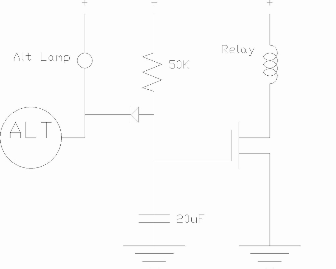
I have NOT actually tested the below schematic; it's just for head-scratching. The 20uF cap should produce about a 1 second delay after the alt light goes out before it closes the relay.
Sep 17, 2014 | 06:38 PM
#4
Registered User
Joined: Jul 2012
Posts: 1,776
Likes: 110
From: Northern Colorado
Your circuit looks like it should work, scope, and I think I'd do something similar if I were doing it. Not so much to keep a run-down aux battery from loading the main battery during starting, but rather to keep a fully charged aux battery from trying to help during starting and burning up the isolation relay and the wiring between the two batteries. Here's the reasons why I say this.
- A discharged aux battery will only pull 10-15 amps max from the main battery, because the main battery can only supply a maximum of 12 volts. The only way to get significant (>20 amps or so) current into a discharged battery is to raise the charging voltage above 13.5 volts or so, and your main battery simply can't do that. 10-15 amps robbed from your main battery won't affect starting at all.
- However, if the aux battery is in good shape, as soon as you close the relay it will try to supply 50% of the starting current. Unless your isolation relay and connecting cable are good for 200 amps or so, something is going to melt.
Scope's circuit should eliminate this possibility by only closing the relay after the alternator voltage is above 12 volts and the batteries are no longer supplying current.
Sep 18, 2014 | 12:52 AM
#5
Thread Starter
Registered User
Joined: Sep 2014
Posts: 507
Likes: 8
From: LA CA
Wow awesome, thank you scope! I'll have to give it a shot.
For the time being I decided to wire a simple switch located next to the parking brake handle. I would still like to keep the switch as an override... in the rare case that I would need to jump my main off of the aux battery.
The wiring to the aux battery is a fairly beefy 4 gauge high strand count wire intended for a high wattage audio amplifier system (I also do a lot of high efficiency mobile PA enclosure design and just got done with the sub which contains the aux battery inside the removable enclosure). The relay is rated for 150A continuous (300A surge), and with the high quality 4 gauge cable going to it I would think 200A would be no problem- especially for a quick burst. This is my first time building an audio system for a car though, hence the confusion.
Thanks for the info about the battery drain, RJR. That is really helpful. I had always wondered how much a dead battery would draw from another. In the past I always have used parallel banks with no relay and obviously never suffer from that problem.
The audio system is all contained within the sub box and is removable, I'm using 375A rated Anderson connectors for the power connection. Everything is built to handle at least 1500W continuous. I'll post a pic when it's painted and done.
Thanks again for the infos. This forum is totally awesome.
Sep 18, 2014 | 04:25 AM
#6
Registered User
Joined: Jun 2014
Posts: 228
Likes: 1
From: North Alabama
Off the top of my head, what about the AFM signal that tells the COR to keep the fuel pump running? That's how the truck "knows" it's running.
Also, suddenly connecting two batteries of different charge can get exciting, quick. What about having them normally connected, then disconnect only during cranking (in case da bass be hitting hard while you're turning the key) or when the SLI battery hits some critical discharge voltage?
Also, suddenly connecting two batteries of different charge can get exciting, quick. What about having them normally connected, then disconnect only during cranking (in case da bass be hitting hard while you're turning the key) or when the SLI battery hits some critical discharge voltage?
Sep 18, 2014 | 06:49 AM
#7
Contributing Member
Joined: Nov 2010
Posts: 5,125
Likes: 4
From: Columbia River Gorge, Oregon...east side
Trending Topics
Sep 18, 2014 | 07:01 AM
#8
Registered User
Joined: Sep 2007
Posts: 8,384
Likes: 875
From: San Francisco East Bay
But your point about current draw through the secondary battery cabling during starting is a really good one. I wonder if a diode in the circuit would be worth considering; so the alternator/starter-side circuit can only source current, not draw it. The diode drop might make charging a problem, though.
Jennigirl might want to verify that her 150amp relay is rated for 150amps DC. It's much easier for a relay to open AC than DC, so the rating is important.
Last edited by scope103; Sep 18, 2014 at 07:03 AM.
Sep 18, 2014 | 07:50 AM
#9
Registered User
Joined: Jul 2012
Posts: 1,776
Likes: 110
From: Northern Colorado
That's probably true for a brand-new fully charged main battery. But I'll bet you know lots of people (with older batteries) in cold N. Colo. who just barely weren't able to get their rig to start -- because they had the headlights (stereo, etc.) on when cranking. After all, the stock Toyota Daytime Running Lights use a similar circuit to keep the headlights off until the alternator comes online.
But your point about current draw through the secondary battery cabling during starting is a really good one. I wonder if a diode in the circuit would be worth considering; so the alternator/starter-side circuit can only source current, not draw it. The diode drop might make charging a problem, though.
Your circuit would have solved my problem, but I was looking for something I could install on the trailer, since I had multiple towing vehicles. That was harder to figure out.
Jennigirl might want to verify that her 150amp relay is rated for 150amps DC. It's much easier for a relay to open AC than DC, so the rating is important.
Sep 18, 2014 | 09:43 AM
#10
Thread Starter
Registered User
Joined: Sep 2014
Posts: 507
Likes: 8
From: LA CA
I definitely don't want a diode because of the voltage drop, it makes a severe difference in charging ability for sure.
Everything is rated for 150A @ 12vdc with the exception of the switch that carries current to the coil of the relay. It's one of those radio shack 125vac 16a switches, more than capable of carrying the <1A 12vdc load the relay coil grabs.
I also have a 150A breaker installed along the 4awg line to the aux battery.
scope- if I attach your schematic in parallel with the switch will that mess anything up? I would like to keep it there to have the option of connecting the two batteries even if the car is off, but it's not so much of a big deal because I think I would hardly ever use that. Honestly I just like having switches that do random things
Sep 18, 2014 | 11:18 AM
#11
Registered User
Joined: Sep 2007
Posts: 8,384
Likes: 875
From: San Francisco East Bay
I presume you mean to put the switch between the drain and source of the FET (so that the switch switches the relay coil, not the load directly); that doesn't hurt anything.
Sep 18, 2014 | 11:37 PM
#12
Thread Starter
Registered User
Joined: Sep 2014
Posts: 507
Likes: 8
From: LA CA
Yeah that's exactly what I did. But, if the box & amplifiers are getting power while the solenoid disconnects, a very loud POP through the speakers occurs. I think it may be the active crossover that's sending the pop -doubt the amps have anything to do with it. When reconnecting the batteries (turning the switch on), I get no audio pops at all.
Unless I can figure out why it is making that noise upon disconnection from the car electric, I'm keeping it manual with the switch alone. Maybe inductance in the cable is sending a voltage spike upon disconnection? Either way it's not a biggie. I just have to make sure to flip the PA off before disconnecting.
For the audio nerds, it's a 2 way system... dual pro 97db 15's in a vented enclosure with compression driver tops loaded on 90/60 directivity horns. Biamped fed with an active 2 way crossover... 1200W continuous available to subs and 300W to the HF compression drivers. It is surely the loudest system I've ever built. I'll be getting my SPL meter & earplugs out tomorrow for some test tones.
Good thing my roommates are all music punks
Sep 19, 2014 | 05:08 AM
#13
Contributing Member
Joined: Nov 2010
Posts: 5,125
Likes: 4
From: Columbia River Gorge, Oregon...east side
Jenny, wish I had something to contribute, but electrical stuff is my weak area. So, I'll try to learn from your electrical threads.
Hope you get the bugs worked out without too much hassle.
Hope you get the bugs worked out without too much hassle.
Sep 20, 2014 | 08:19 AM
#14
Registered User
iTrader: (1)
Joined: Apr 2009
Posts: 13,381
Likes: 100
From: I live in New Tripoli Pa out in the woods
I think if I was doing this if you don`t have a Mechanical oil pressure gauge you will soon.
Put a simple pressure switch in the line once the oil pressure is up to running pressure it closes powering the coil of your relay.
this way your not taking the chance of messing anything up .
Simple to add a switched bypass if needed .
I work with pressure and flow switches so I tend to think that way.
Dec 22, 2014 | 07:12 PM
#15
Thread Starter
Registered User
Joined: Sep 2014
Posts: 507
Likes: 8
From: LA CA
Oh hey btw I recently found a place for this, I am using it for my blackmagic fan routed in series with a kill switch. If you look under the diagnostic jumper box, it's the black wire with red stripe. Only gets +12 with key in ON position
EDIT: actually that is just from memory, I'll have to double check the color of the wire when I get home from visiting parents in OH
Also I was never able to figure out which wire is for the ALT lamp
EDIT: actually that is just from memory, I'll have to double check the color of the wire when I get home from visiting parents in OH
Also I was never able to figure out which wire is for the ALT lamp
Last edited by jennygirl; Dec 22, 2014 at 07:14 PM.
Dec 23, 2014 | 06:40 AM
#16
Registered User
Joined: Jul 2006
Posts: 617
Likes: 4
From: PA USA
Oh hey btw I recently found a place for this, I am using it for my blackmagic fan routed in series with a kill switch. If you look under the diagnostic jumper box, it's the black wire with red stripe. Only gets +12 with key in ON position
EDIT: actually that is just from memory, I'll have to double check the color of the wire when I get home from visiting parents in OH
Also I was never able to figure out which wire is for the ALT lamp
EDIT: actually that is just from memory, I'll have to double check the color of the wire when I get home from visiting parents in OH
Also I was never able to figure out which wire is for the ALT lamp
The black wire with the red stripe is the IG2 wire which supplies + voltage to the following:
-Injectors
-Ignition coil
-Charge light (after passing through 7.5amp ignition fuse)
It sounds like you already found what you are looking for, but in addition to IG2, the IG1 wire also supplies + batt voltage to various components only when the ignition key is in the on position.

Thread
Thread Starter
Forum
Replies
Last Post
v_man
86-95 Trucks & 4Runners
14
Jul 23, 2015 04:01 PM


