When you click on links to various merchants on this site and make a purchase, this can result in this site earning a commission. Affiliate programs and affiliations include, but are not limited to, the eBay Partner Network.
Hi PiTownPi,
LOVELY DETAILED REPORT! I wish everybody would do that.
Busy today and hard to reply via smartphone, but real quickly...
I don't know how low one side of the charge fuse should go in order to cause charge fault light to come on. I only have reading from my truck.
Yes, when u turn Ign on, charge light and brake light should come on. Off whn engine runs and alt starts to generate.
Toyota wired the brake error light to also come on with charge fault light. Maybe to get one's attention better.
With connector unplugged:
"S" wire always has batt voltage, correct? AFFIRMATIVE
"IG" has batt voltage when IGN ON? AFFIRMATIVE
"L" has same voltage from charge fuse? AFFIRMATIVE
Check that thin black wire that is grounded to on of the mounting brackets (P.S. or alt)? Sorry I have not traced exactly where the other end goes to. YUP, checked it..sound, yes, couldn't find where other end is either!
U got a 22RE? YUP, crate motor installed 12 years ago and been running strong, not a single issue really till this alternator saga!
Crate motor installed a 127kmiles, now have 160miles on truck...1988 22RE
Will look more closely. I also had ONE instance of intermittent charge light on last week. As soon as I slowed down to pull over it went away and never came back. LOL!
my brake light has been on for a while, LOL i actually just thought it was the pin not hitting/depressing the switch on the hand brake...this has happened before. but today i unplugged it, checked it's operation, and measured the voltage at that connection...it's only 1 volt!
before recent failure.....the battery charge light came on a few times in past weeks then went off. the other day when i got home on battery power, recharged battery and started.........they both were on.
now with 2nd alternator, only the brake light one is on, i did verify battery charge light works by shorting the yellow to ground at alternator plug. It definitely does NOT come on before starting as it should....
i even made up a 3-wire jumper and installed it between the alternator and plug so i could check all voltages when running...
.nothing unusual..etc. of course only battery voltage is seen at the alternator big wire output.
but battery voltage is going in on the smaller white, S, IG also when ign on, and L has the lower 7.5amp output voltage....
ie if battery voltage is 12.2 then L is around or just below 11voltDC.
this lower voltage on the 7.5amp fuse is key to me, that and the fact that with fuse out it reads 8volts!
like something is shorted to another wire that carries power...??
If indeed my alternator was putting out 19 volts (faulty regulator as ACE Alternators said), it could have fried something? ACE has been in business a long time/family business...so i have to trust them. Ace Alternators in business 70 years
not sure why the other side of the 7.5 fuse socket reads 8 or so when ign on and fuse out..... when running/fuse out reads same instead of alternator charge voltage. also, when the battery voltage drops to 12.2 volts the voltage on the back of the 7.5amp fuse drops below 11volts. shouldn't the voltage at the hand brake switch be 12 volts when unplugged/open looking into the harness?
seems the answer is lying so close under my nose i can smell it!
thanks for any time you give me, i'll be travelling all next two weeks, so was hoping to be able to drive to John Wayne airport tomorrow (Monday) from Joshua Tree... doesn't look like it, will have to take the giant old ford pickup!
Last edited by PitownPi; May 19, 2019 at 01:43 PM.
... If indeed my alternator was putting out 19 volts (faulty regulator as ACE Alternators said), it could have fried something? ...!
EASY ON THE BOLDS AND THE RED LETTERS. I thought you were mad at me. LOL!
Sorry was out of the country for 3 months. Looks like we had similar problem.
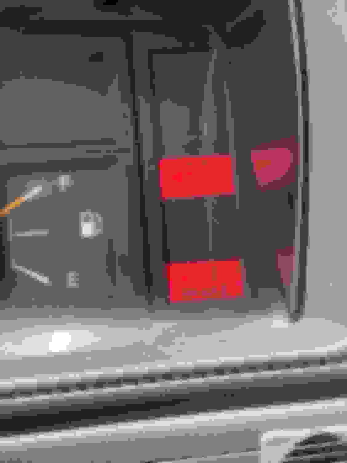
My charge fault light had also been intermittently coming on. Finally was able to stop while it stayed on and verified system was overcharging (17Volts). Problem Description:
1) OReilly charging system checker verified all good - test was done when not in fault condition.
2) Condition seemed to happen at higher RMP. When alt was rotating faster and there was more engine vibration. (Video taken while parked and parking brakes on):
Hypothesis:
Based on (1), If purely electronic problem - say component values/characteristics in regulator has changed, it would be less likely to be intermittent, and should always happen when I rev up the engine.
Based on (1) and (2), more likely a connection issue, or loose component in regulator.
Intermittent connection in "S" pin of alternator would make it think battery needed more charge so it bumps up output, then realizes something must be wrong because bumping up voltage does not fix anything. Charge fault light comes on.
Verify:
"S" wire was OK up to the front of the alt connector. It always had batt voltage.
There is no way to check if regulator is actually getting the 12V through the connector. Best I could do was clean connector pins, swish harness side of connector in, brush it and rinse with, 100% isopropyl alcohol, plug and un-plug connector while moistening with same alcohol to rub off any oxidation, and tightened the brass contacts. Upon reconnection, I went ton 18-mile drive and not a single occurrence. A couple of days earlier, I'd see the problem so many times during similar drive.
ALT CONNECTOR WITH DIELECTRIC SILICONE GREASE AFTER CLEANING AND TIGHTENING THE FEMALE CONTACTS
ALT CONNECTOR, HARNESS SIDE WITH PIN-OUTS
Last edited by RAD4Runner; Sep 12, 2019 at 09:51 AM.
Streamlined charging system wiring some more - 1986 22r-e
Toyota pioneered kaizen and eliminating waste. I am a believer of those so I gave Toyota a dose of its own medicine - LOL!
In the process of checking my alternator wiring, that bulky "intermediate" alt connector caught my obsessive waste/bulk eliminating attention.
The intermediate connector for alternator is pointless.
Why the heck is it there, when 18 inches down the loom there is the main alt connector? (Maybe it made sense from manufacturing Point Of View but not to owner's POV.) It also adds bulk and more parts to break.
Further more, see that black ground wire that runs through the "Intermediate" connector then to the power steering pump bracket? It is NOT a part of the charging system! It is ground wire for the ignitor noise filter. It does not need to run back to the charging system connector then to the power steering pump mount bracket?
I snipped the intermediate connector off, securely twisted mating wires and soldered well, heat-shrunk and cleaned up wiring harness.
I did same to noise filter ground wire so now it physically goes directly to power steering pump bracket.
Now there's one less part to break, the wiring is cleaner, and my truck is a few ounces lighter! LOL!
BLACK WIRE TO POWER STEERING PUMP BRACKET IS GROUND WIRE FOR IGNITOR NOISE FILTER, NOT PART OF CHARGING SYSTEM WIRING.
GROUND WIRE FOR IGNITOR NOISE FILTER, NOT PART OF CHARGING SYSTEM WIRING, YET RUNS A CIRCUITOUS PATH THROUGH CHARGING SYSTEM CONNECTOR AND EVENTUALLY TO POWER STEERING PUMP BRACKET
Last edited by RAD4Runner; Jan 21, 2020 at 02:34 PM.
EASY ON THE BOLDS AND THE RED LETTERS. I thought you were mad at me. LOL!
Sorry was out of the country for 3 months. Looks like we had similar problem.
actually, the 2nd alternator (or internal regulator) i installed was bad, it was from my brothers stash of parts, was a fairly new one too.
i got a rebuilt Denso and all is good now....been motoring along for last 3 months while you were on your adventure!
Alternator Temp and B-Terminal Resistance to Ground
Hi folks,
In original post above, I said ...
Originally Posted by RAD4Runner
... White "B" wire (heavy gauge) to the 80amp fuse
This is the battery charging wire. From FSM:
With engine from idle to 2000RPM, Voltages at B should be:
13.9 to 15.1 V with regulator case @25�C (77�F) Other Toyota alternator write-ups / manuals also specify 13.5 - 14.3V with regulator case @115�C (239�F)
WITH B-WIRE DISCONNECTED, measure resistance from screw terminal to ground. You should get Very high reading. Lots of Meg-ohms (Sorry I forgot how much mine read). If low, suspect bad rectifier (s).
I would like to ask for your opinion and/or actual experience about the following:
1) For the first time, I felt my alternator too hot to the touch @ 150�F. I think this is because it is working hard. My battery was low because ran on battery power only for a few days as I waited to replace the alternator- LOL! Other Toyota manuals mention temps up to 239�F. Have you experienced this? Thoughts please?
2) When I picked up my rebuilt Denso alt from NAPA, I immediately measured resistance from B-terminal stud (output) to metal housing and got 70k-ohms. IIRC, the last time I measured it on an older alternator I got very many meg-ohms - or maybe I just forgot. I expect that to have a very high resistance to ground because of the rectifiers. May I know what resistance you get with nothing connected to that B-terminal stud?
Last edited by RAD4Runner; Sep 17, 2020 at 10:01 PM.
Hi folks.
Just for the heck of it, I measured my truck's current draw with ignition switch off and I got 20 mA. I think that's for the following:
1) ECU memory
2) Radio memory
OOPS! I should have also done measurements with ACC on and IGN on. Oh well...
Here's test setup for everyone's convenience:
keywords: batterycircuit, currentdraw, powerdistribution, battery circuit, current draw, power distribution
I'm going to bring up an ancient thread because it seems most relevant. I have 12v at the L terminal even with the key off. Charge light never comes on, even with key to on and engine off. Also have constant 12v on charge fuse. I noticed because the electric choke was always hot, and started tracing backwards.
**edit** just realized if I pull the charge fuse with the truck running, the charge light does come on. I have no idea what that means.
What is my next step?
Last edited by Overtravel; Jun 29, 2021 at 06:42 PM.
UPDATED WITH GOOGLE PHOTOS
(I'm posting this here so it will be easier to refer to, rather than re-typing explanation into various threads that need the explanation.)
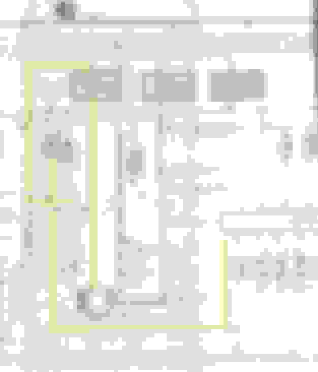
Here's the 22RE-liable schematic:
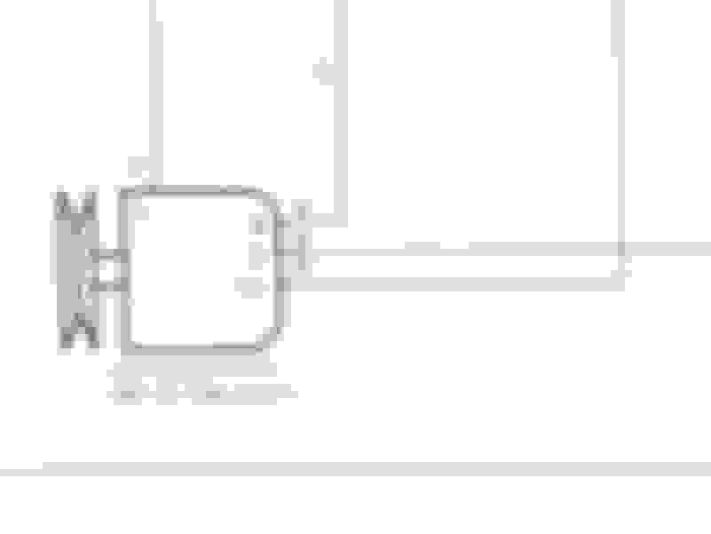
Close-up of alternator pin-outs is here:
White "B" wire (heavy gauge) to the 80amp fuse
This is the battery charging wire. From FSM:
With engine from idle to 2000RPM, Voltages at B should be:
13.9 to 15.1 V with regulator case @25�C (77�F) Other Toyota alternator write-ups / manuals also specify 13.5 - 14.3V with regulator case @115�C (239�F)
WITH B-WIRE DISCONNECTED, measure resistance from screw terminal to ground. You should get Very high reading. Lots of Meg-ohms (Sorry I forgot how much mine read). If low, suspect bad rectifier (s).
White "S" to the 40amp (always-on) fuse Tt should read as close to battery voltage as possible. This senses actual battery voltage and should be connected as close as possible to battery positive. It is merely spliced with the B wire near or at the junction of 80-Amp fuse and 80-Amp fusible link wire. Low "S" voltage means battery needs more charge so the regulator would increase output voltage. If "S" wire and or connection is bad it could lead to overcharging and charge fault error light would come on.
Red "IG" to the Engine fuse
This provides field current to "seed" the charging. This should have steady 12V when ignition is on (coming from Engine fuse). If no 12V here or if this voltage is erratic or engine fuse blows, trace wiring back to Engine Fuse, to "E" battery positive wire from fuse block, and verify that your backup switch or wiring is not shorting to transmission body as shown here.
Yellow "L" to the Charge Warning Light
This should be near +battery voltage when alternator is working properly (B voltage 13.5V-15.1V). If there is a charing fault "L" will go low - approaching zero, and provide ground to negative side of the Charge Light causing it to come on.
(Unfortunately, it also provides ground to Brake Light and A/T Oil temp light- making it confusing to many.)
Most accessible place to measure "L" voltage is here:
ALTERNATOR HARNESS AND MORE VOLTAGE TESTS OF NORMALLY-FUNCTIONING CHARGING SYSTEM:
The engine compartment wiring harness has an "intermediate" connector along the left inner fender, near the power steering pump, shown below:
Pin-outs are as follows:
How would I connect to this alternator, I have an 86 4Runner. I tried re-connecting the way they where on old alt but didn�t work. I have 3 wires red, white, yellow. Auto zone says this is off an 84
How would I connect to this alternator, I have an 86 4Runner. I tried re-connecting the way they where on old alt but didn�t work. I have 3 wires red, white, yellow. Auto zone says this is off an 84
Sorry. I don't know what that alternator is. I strongly-recommend using rebuilt OEM to be safe and save you time and money in the long run.
If it is from n 84, I think that uses an external regulator and is not plug-and-play into the 1986.
I originally asked for a 1986 alternator but was something totally different so I looked around and what was in the truck looked just like an alt for a 1984 so that’s what I got. My core is now gone. 🤦♂️ I’ll call around see what I can do
Minimize risks, save the time, money, tylenol. Consider Remanufactured Denso.
Got my Denso, manufactured with pride in the U.S.A., not made in the Communist Bully, from LOCAL NAPA for $142 + tax. Best deal because I would not have to worry or pay for shipping the core.
I also like McGeorge Toyota. Got me better prices for the past couple of purchases compared to Toyota Part Deal. So to date, I compare total cost between that, Lakeland and TPD.
Reman by Denso in the U.S.A. $143 Plus tax from NAPA. Excludes core refund.
UPDATED WITH GOOGLE PHOTOS
(I'm posting this here so it will be easier to refer to, rather than re-typing explanation into various threads that need the explanation.)
Here's the 22RE-liable schematic:
Close-up of alternator pin-outs is here:
White "B" wire (heavy gauge) to the 80amp fuse
This is the battery charging wire. From FSM:
With engine from idle to 2000RPM, Voltages at B should be:
13.9 to 15.1 V with regulator case @25�C (77�F) Other Toyota alternator write-ups / manuals also specify 13.5 - 14.3V with regulator case @115�C (239�F)
WITH B-WIRE DISCONNECTED, measure resistance from screw terminal to ground. You should get Very High reading. I get 75 kOhms. That translates to 0.16milliamps draw from battery. If R is low, suspect bad rectifier (s).
White "S" to the 40amp (always-on) fuse Tt should read as close to battery voltage as possible. This senses actual battery voltage and should be connected as close as possible to battery positive. It is merely spliced with the B wire near or at the junction of 80-Amp fuse and 80-Amp fusible link wire. Low "S" voltage means battery needs more charge so the regulator would increase output voltage. If "S" wire and or connection is bad, regulator would think batt V is low and keep on increaing chargincharging V, which could lead to overcharging and charge fault error light would come on.
Red "IG" to the Engine fuse
This provides field current to "seed" the charging. This should have steady 12V when ignition is on (coming from Engine fuse). If no 12V here or if this voltage is erratic or engine fuse blows, trace wiring back to Engine Fuse, to "E" battery positive wire from fuse block, and verify that your backup switch or wiring is not shorting to transmission body as shown here.
Yellow "L" to the Charge Warning Light
This should be near +battery voltage when alternator is working properly (B voltage 13.5V-15.1V). If there is a charing fault "L" will go low - approaching zero, and provide ground to negative side of the Charge Light causing it to come on.
(Unfortunately, it also provides ground to Brake Light and A/T Oil temp light- making it confusing to many.)
Most accessible place to measure "L" voltage is here:
ALTERNATOR HARNESS AND MORE VOLTAGE TESTS OF NORMALLY-FUNCTIONING CHARGING SYSTEM:
The engine compartment wiring harness has an "intermediate" connector along the left inner fender, near the power steering pump, shown below:
Pin-outs are as follows:
do you happen to know where that black ground that is not part of the alternator wiring goes too it's bad and I'm pretty sure it's causing my truck not to start it's a 1985 Toyota pickup with 22re
do you happen to know where that black ground that is not part of the alternator wiring goes too it's bad and I'm pretty sure it's causing my truck not to start it's a 1985 Toyota pickup with 22re
If you follow that wire one end goes to either power steering pump bracket. That's basically block ground. The other to the noise suppression capacitor for the ignitor, I think. Just find a good ground and you're good.
1987 toy pickup has the charge light on...
what a pain in the butt the fix was..
i put in 3 different alternators, fixed the (yellow charge wire connector) removed and repaired all the larger positive wires traced it back to the idiot lights removed and replaced the diodes (was not fun because the plastic they are soldered to doesnt like heat. repaced the bulbs in behind the speedo... pulled dash all apart, ended up being the large wire inside the harness under the tape was rusted where it connects to 2 smaller wires just to the left of the battery.... i pushed the battery aside and started slicing tape off and there it was 6guage wire crimped to 2 10 guage wires (white) coming from the nut off the alternator. and boooom i had 14.5vdc at the battery and wow i can start the truck in miliseconds now...
here is the situation... i used a 6 guage butt connector to reconnect it cus the wire is too large to solder (tried soldering it) will i need to find a better solution later? also when i drive at night i can still see the charge light barely lite does this mean i still have a fault in my curcuit?
... also when i drive at night i can still see the charge light barely lite does this mean i still have a fault in my curcuit?
Sorry, I have a hard time following all that you did. Were everything you replaced/rewired defective? Some parts you are describing do not sound familiar. I prefer to leave things as stock as possible. Difficult to troubleshoot/analyze things that have been heavily-modded.
Nevertheless...
the large wire inside the harness under the tape was rusted where it connects to 2 smaller wires just to the left of the battery
those are the thick Alt to Batt wire and the "S" wire.
...also when i drive at night i can still see the charge light barely lite does this mean i still have a fault
Maybe you are simply seeing dash backlight through the red lens of the charge fault light. Do you see fault light IF you turn off dash lights? Furthermore, a charge fault WILL also turn on the brake fault light.
If you are getting voltages I mention in original post, you should be fine.
Last edited by RAD4Runner; May 9, 2022 at 11:09 AM.
Hi i have a 89 toyota PU 22r engine. the battery light is on. i tested the charge fuse both sides read 3.57 and the socket left side read 3.57 and the right side 0. i also pulled the charge fuse out and light still stayed on. car off battery reads 13.4volts car on battery reads 14.4 volts. i cleaned battery contacts also and tightened every thing back down,

 May 19, 2019 | 01:40 PM