
DIY headlight wiring harness upgrade for low $$
 Nov 20, 2010 | 05:50 AM
#82
Registered User
Joined: Aug 2009
Posts: 13,574
Likes: 72
From: Wilkes-Barre, PA, USA
irab88 narrowed the problem down to something with the HB indicator light using the low beam wiring and to use a high watt resister parallel to the LB relay, that's all I Know, I haven't done it, I like the idea of the low beam staying on with the high beam. I don't remember if iamsuperbleeder's setup had the LB's on with the HB's or not.
Nov 20, 2010 | 07:03 AM
#84


 everyone figure their issues out?
Nov 20, 2010 | 08:58 AM
everyone figure their issues out?
Nov 20, 2010 | 08:58 AM
#86
Registered User
Joined: May 2008
Posts: 3,948
Likes: 11
From: Calgary, AB Canaduh
Nov 20, 2010 | 09:44 AM
#87
Registered User
Joined: Aug 2009
Posts: 13,574
Likes: 72
From: Wilkes-Barre, PA, USA
Nov 20, 2010 | 11:25 AM
#88
Registered User
Joined: Aug 2008
Posts: 360
Likes: 0
From: Southern OR
how come your guys schematics ground the stock plug? Wouldn't that create a short since 12V comes out of the common????
Your guys schematic and 4 crawlers are totally different..which one is correct?
Your guys schematic and 4 crawlers are totally different..which one is correct?
Last edited by PirateMcgee; Nov 20, 2010 at 11:33 AM.
Nov 20, 2010 | 11:35 AM
#89
Registered User
Joined: Aug 2009
Posts: 13,574
Likes: 72
From: Wilkes-Barre, PA, USA
do you even know and understand how a relay works? I do not understand why you are not getting the fact I followed my diagram and mine is working, if yours is not, time to start from scratch.
Nov 20, 2010 | 11:41 AM
#90
Registered User
Joined: Aug 2008
Posts: 360
Likes: 0
From: Southern OR
The relay has nothing to do with grounding the stock plug......there is 12V coming out of the common regardless of if the HB or LB is on. So if this is connected to ground wouldn't that create a short? I understand the 12V coming out of the stock LB or HB in turn flips the switch in the relay. Not trying to be a jerk I just have some questions. If you don't want to clarify then don't
Last edited by PirateMcgee; Nov 20, 2010 at 11:52 AM.
Nov 20, 2010 | 11:43 AM
#91
Registered User
Joined: Aug 2009
Posts: 13,574
Likes: 72
From: Wilkes-Barre, PA, USA
explain how the factory plug is being "grounded". oh and You might wanna watch the language mods don't like it.
my diagram to make it easier. I am also going to go out and check to make sure this is exactly what I ended up doing.
my diagram to make it easier. I am also going to go out and check to make sure this is exactly what I ended up doing.
Last edited by xxxtreme22r; Nov 20, 2010 at 11:49 AM.
Nov 20, 2010 | 11:56 AM
#92
Registered User
Joined: Aug 2008
Posts: 360
Likes: 0
From: Southern OR
just checked everything and my relays are turning on an off fine and turning on the correct wires but when I plug in a bulb I get 12V (on the new socket) from the terminal that is supposed to go to ground in your schematic.
Nov 20, 2010 | 12:02 PM
#94
Registered User
Joined: Aug 2009
Posts: 13,574
Likes: 72
From: Wilkes-Barre, PA, USA
remember factory wiring is switched ground, the wiring after the relays will be switched power.
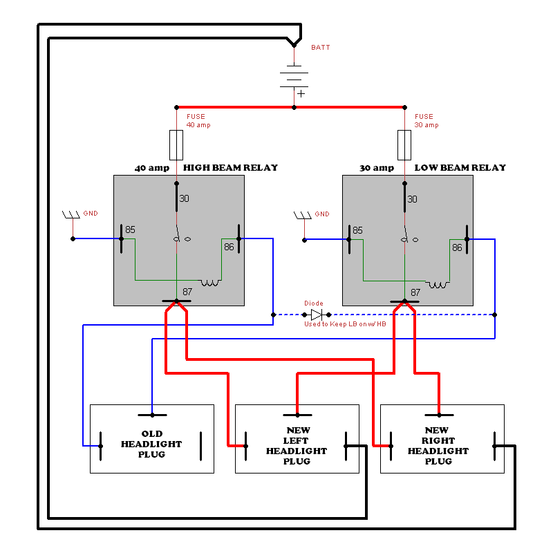
turns out though, I wired mine slightly different than that diagram and figured out why my lows stay on with my highs. On the old plug I have all three pins taken up not just two. I have two wires on the 12V common that goes to the 85 pin one on each relay. then each 86 pin on the two relays comes back to the factory plug as grounds as showed in that diagram.
in short, where it says "GND" on each 85 pin on the relays they are actually to +12v or back to the factory headlight plug.
I think I might have made that diagram before I realized these plugs were switched ground. Gonna make a new diagram shortly.
Last edited by xxxtreme22r; Nov 20, 2010 at 12:10 PM.
Nov 20, 2010 | 12:03 PM
#95
Registered User
Joined: Aug 2008
Posts: 360
Likes: 0
From: Southern OR
this is 4crawlers diagram
http://www.4crawler.com/4x4/CheapTri...lightSG-SP.gif
see how the stock plug is connected....this is why I am confused lol
http://www.4crawler.com/4x4/CheapTri...lightSG-SP.gif
see how the stock plug is connected....this is why I am confused lol
Nov 20, 2010 | 12:15 PM
#96
Registered User
Joined: Aug 2009
Posts: 13,574
Likes: 72
From: Wilkes-Barre, PA, USA
see above comment. mine is like 4crawlers, i just didn't use his as a reference. only difference is my 85 and 86 pins are in reverse which is fine, doesn't matter which direction you send the power to the relay coil.
Nov 20, 2010 | 12:22 PM
#98
Registered User
Joined: Aug 2009
Posts: 13,574
Likes: 72
From: Wilkes-Barre, PA, USA
np. now to change that diagram. and looking at iamsuperbleeders I see why he needs the diode in his, he is using the high beam relay to trip the low beam relay when the high beam is on. this keeps the lows on with his. the diode is there so the low beam relay does not trip the high beam relay.
Nov 20, 2010 | 12:40 PM
#99
Registered User
Joined: May 2008
Posts: 3,948
Likes: 11
From: Calgary, AB Canaduh
remember factory wiring is switched ground, the wiring after the relays will be switched power.
turns out though, I wired mine slightly different than that diagram and figured out why my lows stay on with my highs. On the old plug I have all three pins taken up not just two. I have two wires on the 12V common that goes to the 85 pin one on each relay. then each 86 pin on the two relays comes back to the factory plug as grounds as showed in that diagram.
in short, where it says "GND" on each 85 pin on the relays they are actually to +12v or back to the factory headlight plug.
I think I might have made that diagram before I realized these plugs were switched ground. Gonna make a new diagram shortly.
dude thanks! ill buy you a beer if you ever come to calgary


